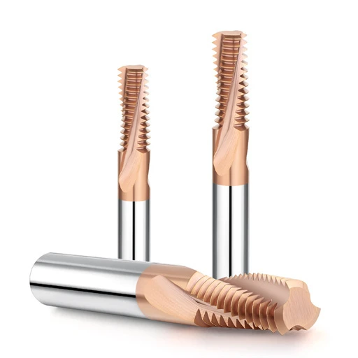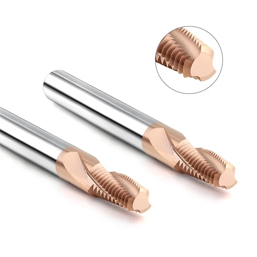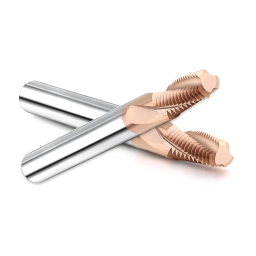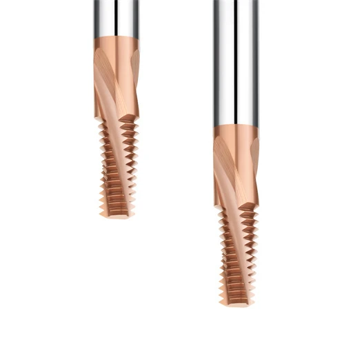

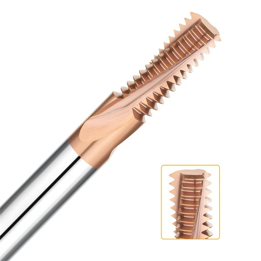
Last winter, a long-standing client in Stuttgart reached out with an urgent problem. They needed to add four M6 internal threaded holes to a D2 stamping die insert. The block was already vacuum-hardened to HRC64–65. The operator tried to tap the holes with a standard carbide tap, but it snapped after engaging just two threads. That broken tap put a multi-thousand-dollar workpiece at risk and threatened a two-day EDM delay.
Over the past sixteen years, we have seen this scenario play out every single month across European and American machine shops. Once a workpiece crosses HRC60, traditional cutting mechanics fail. Heat-treating parts after tapping often warps precision thread tolerances out of spec, while burning threads on an EDM sinker devours valuable cycle time. In our field experience, internal thread milling hardened steel is the only reliable way to cut accurate threads without scrapping expensive components.
Yet this process is never as simple as dropping in a generic thread mill tool. If your carbide grain size is wrong or the relief angle lacks support, the cutting edge micro-chips instantly. If your tool holder dynamic runout exceeds 0.003 mm, one flute absorbs the entire load and fractures. A mere 0.003 mm variance in your feed path, cooling method, or chip load will leave you with tapered threads or stuck gauges.
So, should you set up a single profile thread mill or a multi-row thread mill? In HRC65 cuts, is coolant or blast air the real culprit behind edge chipping? And how do you program your tool path to offset tool deflection? Imagine an HRC65 die block sitting on your VMC right now. Are you confident your first tool path will pass a Go-gauge on the very first try?
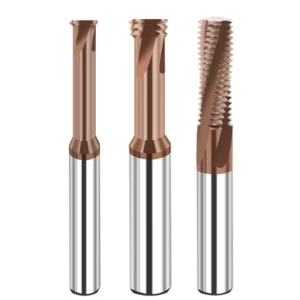
Overcoming Bottlenecks in Internal Thread Milling Hardened Steel
In Western mold and tooling shops, workpieces hardened past HRC60 frequently create the worst bottleneck on the floor. We regularly troubleshoot jobs where engineers pushed core hardness to maximize wear resistance, only to get trapped on the final threading pass. The extreme yield strength of these materials cuts your margin of error down to zero.
To mill threads reliably at this hardness, you must eliminate the continuous friction that traps heat in the hole. We guide teams through internal thread milling hardened steel by using helical interpolation to break continuous cutting resistance into interrupted, manageable cuts. It requires disciplined setup, but it remains the most dependable method to prevent scrapped dies and damaged threads.
Why Taps Frequently Break on Hardened Workpieces: Western Scrap Case Review
We analyzed a costly scrap incident for an automotive stamping shop in Detroit. The team was running M5 holes into HRC63 cold-work die inserts using ultra-fine micrograin carbide taps. Even with premium taps, brittle fractures occurred by the third hole. Taps lodged tightly in blind holes, and EDM burning annealed the thin adjacent walls, turning expensive inserts into scrap.
The failure stems from physics: taps run a fully enclosed cut where flutes choke with abrasive, powdery chips. When tapping materials beyond HRC60, tiny spindle synchronization lags cause massive torque spikes that snap brittle carbide instantly. Forcing taps through ultra-hard steel is simply a high-risk gamble on modern shop floors.
Thread Milling D2 Tool Steel After Hardening: Shifting from EDM to CNC Threading
Many machinists who get burned by broken taps swing to the other extreme: running every threaded hole on an EDM sinker. In European shops, we often see teams spend half a day turning graphite or copper electrodes just to burn threads into hardened D2 blocks. While EDM eliminates cutting forces, its hidden production costs are severe.
First, multi-stage roughing and finishing electrodes make cycle times drag on for hours per hole. More critically, EDM leaves a 0.01–0.03 mm brittle “white layer” and micro-cracks on D2, which peel and spall under heavy stamping cycles. Switching to thread milling D2 tool steel on a rigid CNC mill finishes each hole in minutes with zero thermal damage.
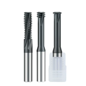
Selecting an Internal Thread Milling Cutter for Hardened Workpieces
Machining HRC 60–65 steel turns conventional tool selection upside down. The real threat is not progressive flank wear, but catastrophic micro-chipping. In North American die shops, we often see operators try standard steel mills, only to watch the edges shatter on initial contact. Extreme hardness creates brutal shear loads that instantly destroy unsuited tool geometries.
Selecting the right internal thread milling cutter requires balancing instantaneous tooth contact against overall tooling rigidity. Neck relief, tooth pitch, and overhang dictate whether your setup chatters inside the bore. You cannot buy one cutter that delivers maximum speed and bulletproof safety. In ultra-hard steels, every choice trades cycle time for edge survival.
Single-Profile Thread Mills: The Top Choice for Deep Holes and Extreme Hardness
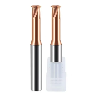
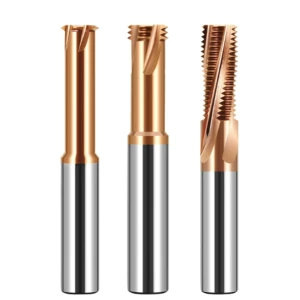
For materials above HRC 62—especially with depth-to-diameter ratios beyond 2.5 or small bores like M3 to M6—a single profile thread mill is our first choice for lights-out machining. Its physical advantage is simple: only one tooth engages the material at any point in the cycle. This slash in radial cutting pressure protects both your spindle and your tool holder from violent deflection.
A Swiss medical client needed M4×0.7 threads in blind HRC64 inserts with zero taper tolerance. Full-form cutters shrieked under the load and left severe chatter marks on the flank. We switched them to a single-tooth cutter climbing along the helix. The noise smoothed out, chatter disappeared, and tool life stabilized. Sacrificing a few seconds of cycle time to eliminate scrap is always the right call.
Multi-Row Thread Mills: Balancing Speed, Cutting Pressure, and Tool Failure
We do not write off multi-tooth tools entirely. A multi-row thread mill remains unbeatable for speed because it cuts the full thread profile in a single 360-degree orbit with one axial pitch feed. In high-volume stamping setups cutting shallow holes between HRC 60 and 62, this design multiplies daily output while keeping tool overhang under 1.5×D.
However, you must respect its mechanical threshold. Multiple teeth cutting hardened steel simultaneously create a long contact line, sending radial push forces soaring. In our UK shop trials on HRC65 blocks at 2×D depth, tool deflection produced nearly 0.02 mm of taper and snapped teeth upon entry. Unless your VMC has tremendous spindle rigidity and open chip clearance, running multi-flute tools at HRC65 introduces unnecessary risk.
Substrate Grain Size and Heat-Resistant Nanocoatings for HRC60–65
Macro-geometry controls cutting forces, but carbide microstructure dictates high-temperature resistance. When grinding our custom internal thread milling tools, we reject standard 0.6–0.8 μm carbide grades. Instead, we use ultra-fine 0.2–0.4 μm tungsten carbide substrates with reduced cobalt content. This dense matrix resists thermal softening and stops micro-chipping before it starts.
Standard TiN or TiAlN coatings oxidize and burn out within three holes under dry HRC65 cutting conditions. We specify an AlTiSiN nanocomposite coating with micro-hardness exceeding HV 3600 and thermal stability up to 1100°C. In the cut, the silicon content forms an amorphous barrier layer that blocks friction heat from reaching the carbide substrate.
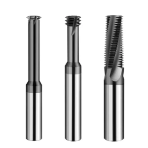
Toolpath Planning and Internal Thread Milling Strategies for HRC65
Even a premium micrograin cutter will fail on its first revolution if programmed with aggressive, linear entry moves suited for soft steels. In HRC65 workpieces, the tool operates at its absolute mechanical limit. Because the workpiece cannot yield plastically, abrupt toolpath changes slam into the flutes as destructive shock loads.
Proven internal thread milling strategies focus on maintaining constant chip thickness and steady cutter engagement. Your CAM program must account for three-axis dynamics, tool deflection, and thermal buildup in the bore. Thoughtful toolpaths turn high-impact shocks into predictable, smooth cutting cycles.
Eliminating Taper Error with Climb Milling and Multi-Pass Radial Infeed
If you mill threads in deep, hardened holes, you have likely seen pitch gauges bind at the mouth or float loose at the bottom. This thread taper error comes straight from tool shank deflection. At a North American powder metallurgy facility, operators tried cutting M8 threads in a single pass. Extreme radial push forced the slender tool to back off, leaving bottom threads 0.03 mm undersized.
We fix this by pairing climb milling with three progressive radial passes—typically 60%, 30%, and 10% of total thread depth—followed by a zero-depth spring pass. Climb milling produces a chip that thins as it finishes, minimizing rubbing. Breaking the depth into controlled steps keeps lateral pressure well within the tool’s elastic limits.
1/4-Arc Entry and Exit: Preventing Chipping at the Tool Tip
Straight 90-degree plunges into HRC65 sidewalls act like slamming carbide into a brick wall. Microscopic shop inspections reveal that linear entries create severe mechanical impact spikes, sparking micro-cracks along carbide grain boundaries. The flutes may not snap immediately, but damaged grains quickly flake away, ruining thread pitch surfaces.
We mandate a smooth 1/4-arc entry and exit on every job. The tool drops to depth down the hole center, sweeps into the cut along a tangential circular arc, and matches full cutting depth smoothly. It exits along the same smooth arc before retracting. This simple trajectory change removes sudden shock loads and keeps cutting edges intact.
Coolant Selection: Why We Ban Water-Based Coolants for Air Blasts
Machinists often ask: “With all this heat in HRC65 steel, why turn off the flood coolant?” In high-hardness internal thread milling, water-based emulsions trigger premature failure. Interrupted cutting causes flutes to heat up and quench several times per revolution. This thermal shock breeds microscopic comb cracks across the tool face, destroying the edge within minutes.
We enforce dry cutting backed by 6 to 8 bar of clean compressed air aimed right at the cut. Adding a cold-air vortex gun dropping air to 0°C yields even better edge life. Ultra-hard cutting generates fine, powdery chips; if left in the hole, the tool crushes them, leading to chipped flutes. High-velocity air evacuates chips instantly so the flutes only cut fresh material.
Tool-Holding Systems and Thread Mill Runout Control
When edge chipping occurs, machinists often blame the tool coating or cutting speeds first, ignoring the tool holder. In structural steels, a tool-tip deviation of 0.010 mm or 0.015 mm might slide by due to material ductility. At HRC65, however, the workpiece has zero plastic give; any runout amplifies directly into violent, cyclical impacts.
Establishing a rigid, high-precision clamping assembly is mandatory for reliable thread mill runout control. The holder must do more than transfer spindle torque—it must absorb high-frequency chatter and balance chip loads evenly across every tooth. Unless you control taper cleanliness, dynamic balance, and bore tolerance, premature edge failure is guaranteed.
Why Thread Mill Runout Must Be Kept Below 0.003 mm
A Belgian hydraulic manufacturer milling M6 threads into HRC63 440C stainless was burning through tools every 4 to 6 holes. Laser measurement showed their dynamic tool-tip runout was 0.008 mm. With a programmed chip load of only 0.010 mm per tooth, this runout forced one tooth to take nearly 200% of the cutting load while the opposite flute barely touched the cut.
We ground the spindle interface, upgraded the tool holder, and clamped total thread mill runout strictly under 0.003 mm. The squealing stopped instantly, and tool life jumped past 28 holes with smooth, uniform flank wear instead of chipping. In HRC62–65 cutting, 0.003 mm is not a theoretical textbook figure; it is the physical threshold between tool survival and brittle fracture.
Shrink-Fit vs Hydraulic Tool Holders: Avoiding Collet Chuck Runout
If your shop still cuts ultra-hard threads using standard ER collet chucks, stop the spindle and swap them out immediately. An ER setup stacks manufacturing tolerances across the holder body, split collet, and clamping nut, routinely driving runout past 0.010 mm. Under heavy cutting resistance, collets flex radially and spark micro-chatter that destroys brittle carbide teeth.
We choose exclusively between shrink-fit and high-precision hydraulic holders. Shrink-fit tooling delivers a slim nose profile, high clamping force, and superior concentricity for deep bores with long overhangs, though its solid steel body offers minimal damping. Hydraulic holders use an internal pressurized oil membrane that absorbs interrupted cutting shocks; if your spindle is slightly worn, hydraulic damping will extend edge life significantly.
Cutting Parameter Benchmarks and Optimization for Internal Thread Milling Tools
Every mechanical safeguard—from single-tooth selection to 0.003 mm runout limits—culminates in the feeds and speeds keyed into your CNC control. We often see operators swing between extremes: dialing RPM down out of fear (which rubs and work-hardens the cut) or pushing aggressive feeds that overload the cutter’s structural limits.
Parameter tuning is the science of matching coating heat resistance with mechanical chip loads. Running internal thread milling tools within balanced windows activates the self-lubricating oxide layer on modern nanocoatings while blocking thermal transfer into the carbide core. Proper parameter boundaries turn high-risk threading into a repeatable, standard production step.
Recommended Cutting Speed (Vc) und Futter pro Zahn (fz) for HRC 62–65
For D2, DC53, and hardened powder-metallurgy tooling steels, keep your cutting speed (Vc) between 35 and 55 m/min. With a balanced spindle and nano-composite coated cutters, you can cautiously push to 60 m/min, but stay below 70 m/min to prevent thermal softening of the carbide binder. Below 30 m/min, you lose the chip-thinning benefits of interrupted cuts, which accelerates friction and flank wear.
Target a chip load (fz) between 0.006 and 0.012 mm/tooth. If you run a small-diameter cutter with long overhang, start your test cuts at 0.008 mm/tooth alongside radial multi-pass indexing. If your setup features a high-rigidity spindle and hydraulic clamping, you can drop your final finish pass to 0.005 mm/tooth to produce mirror-like thread flank finishes.
Compensating for Thread Mill Tool Wear via CNC Radius Offsets (G41/G42)
In ultra-hard cutting, micron-level flank wear creeps in long before a tool visibly chips, directly affecting your pitch diameter. When setting up a new thread mill tool, program a +0.020 to +0.030 mm radial offset (using G41/G42). If your Go gauge binds on entry, step down the tool radius in 0.005 mm increments until the Go gauge spins through and the No-Go gauge locks within two turns.
As part counts climb, natural tool wear makes the Go gauge fit tighter. If you run production batches of expensive dies, inspect threads with a Go gauge every 8 to 10 holes. When you feel drag on the gauge, adjust your tool radius offset by -0.003 mm to correct for wear before parts drift out of tolerance.