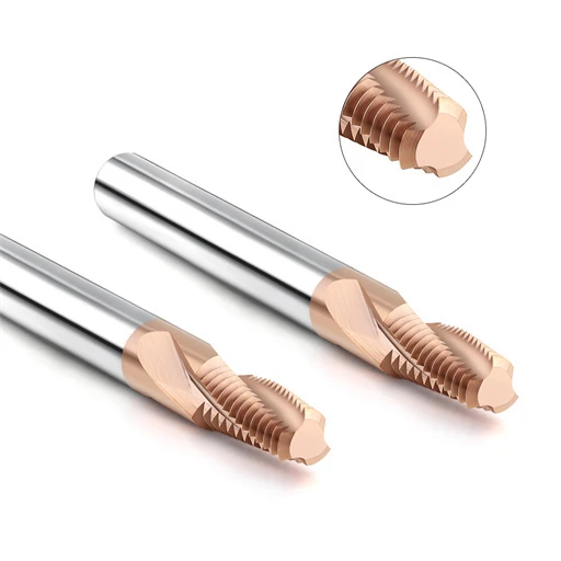


Last month, we helped a German contract manufacturer troubleshoot a high-stakes job. The workpiece was Böhler M390 powder-metallurgy steel, heat-treated to an actual hardness of HRC 64–65. They needed to cut 48 blind-hole M1.6×0.35 threads at a challenging 2.8D depth-to-diameter ratio. Their process engineer broke four consecutive cutters at the neck transition and the first tooth root. The machine alarmed out, leaving a multi-thousand-euro mold insert at immediate risk of being scrapped.
Over our 16 years of on-site CNC technical support across North America and Europe, we have seen this failure pattern repeatedly. Once workpiece hardness passes HRC 62, standard cutting mechanics break down. Simply copying catalog feeds for a solid carbide micro thread mill or running standard helical interpolation paths causes sudden micro thread mill breakage. At HRC 65, material yield strength spikes and plastic deformation disappears entirely.
Consistency in micro thread milling hardened steel requires more than tool hardness or luck. Scrapping dozens of test batches taught us how to engineer a real micro thread milling strategy. That foundation demands selecting a micro thread milling cutter with high-rigidity core geometry, holding tool runout below 3μm, programming smooth tangential arc-ins, and step-balancing your radial multi-pass passes.
If your setup suffers from snapped cutters, pitch shrinkage, or thread taper, take a step back and examine the setup. Does the root cause lie in the sub-2mm tool itself, or did an abrupt entry path doom it from the start?

Shop-Floor Reality: Why Do Standard Solid Carbide Micro-Thread Mills Frequently Fail in HRC65 Materials?
Many machinists instinctively grab an off-the-shelf solid carbide micro thread mill when setting up a hardened job. These tools cut cleanly in HRC 50 steels, but they fail fast once hardness passes HRC 62. Operators often stare at the spindle load meter without seeing a spike. The micro-cutter simply snaps at the hole bottom before the control can even register the load.
Standard carbide geometries compromise between chip space and edge sharpness. On HRC 65 layers, standard edge honing is too thin to resist extreme shear stress. Deep flutes also gut the core rigidity needed on sub-millimeter shanks. When material hardness nears tool substrate limits, cutting degrades from clean shearing into forced, abrasive rubbing that snaps standard tool profiles instantly.
From Tip Spalling to Catastrophic Failure: Three Primary Causes of Micro Thread Mill Breakage on the Shop Floor
In our lab post-mortems of failed cutters, catastrophic micro thread mill breakage rarely starts as a sudden overload snap. It almost always stems from micro-scale fatigue. The most dangerous culprit is chip re-cutting inside tight blind holes. Sub-micron powder packs into the thread roots. On the next helical pass, the tooth runs over these HRC 65 particles, stripping the ultra-thin coating off the tip.
Once the coating spalls, the exposed tungsten carbide heats up rapidly from friction. Cutting resistance spikes, triggering high-frequency tool chatter. The tiny extended neck deflects, sending fatigue micro-cracks from the first thread root directly into the solid carbide core. Our shop data shows that over 70% of tool failures start as tiny 2–3 micron edge chips that cause total breakage within a few spindle revolutions.
Critical Thresholds for Toughness and Micro-Chipping in Cold-Work Die Steels vs Powder-Metallurgy Steels
Even at an identical HRC 65 reading, different alloy microstructures assault micro-cutting edges in completely different ways. Matching your setup to the metallurgy is essential when micro thread milling hardened steel. Take cold-work tool steels like vacuum-treated D2 or DC53. Their structures carry coarse, banded primary carbides that hit a sub-2mm tool like miniature anvils during high-speed rotation.
Powder-metallurgy (PM) steels like Böhler M390 or CPM 10V feature uniform carbide dispersion, but their dense matrix creates constant, heavy cutting drag. When we cut cold-work tool steels, we select ultra-fine sub-micron carbide grades (0.4μm grain size) for maximum impact resistance. On PM steels, we drop the radial depth of cut to keep the chip load well under the micro-chipping limit, relying on smooth compressive shearing to protect the edge.
Coating Adhesion and Thermal Barriers: Real-World Tool Life of AlTiN vs AlCrN Under Dry Cutting and MQL
At extreme hardness, coatings act as thermal armor rather than simple wear skins. Many operators default to high-aluminum AlTiN for its nominal surface hardness. However, our field tests on HRC 65 blocks show that an AlCrN-coated micro thread mill for hardened steel delivers superior adhesion and peel resistance. In dry cutting, AlCrN forms a dense chrome-oxide layer stable past 1,000°C, stopping rapid edge softening in its tracks.
Choosing between dry air and MQL comes down to how you evacuate chips. Dry cutting with an air blast avoids thermal-shock micro-cracking, provided air pressure blows the dust completely out of the hole. For blind holes deeper than 2D, MQL oil mist cuts frictional drag and improves thread surface finishes. Toutefois, the mist flow must stay perfectly steady; sputtering oil causes thermal cycling that spalls tool coatings in seconds.

Tool Selection and Rigidity Control: Structural Advantages of Custom-Grade HRC65 Micro Thread Mills
When tools snap in HRC 65 steel, machinists instinctively drop the feed or spindle speed. Our field experience shows the true problem usually starts at tool selection. Above 2200 MPa tensile strength, lateral cutting forces climb exponentially. Standard tools built for softer mold steels simply lack the section modulus to survive these side loads.
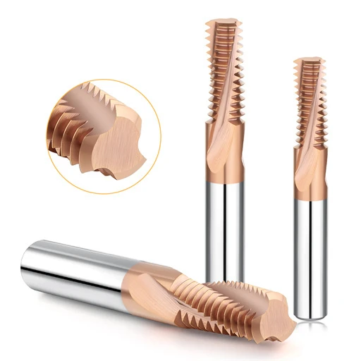
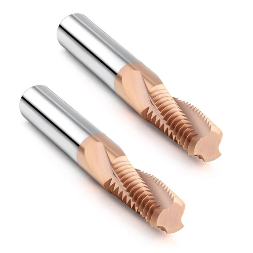
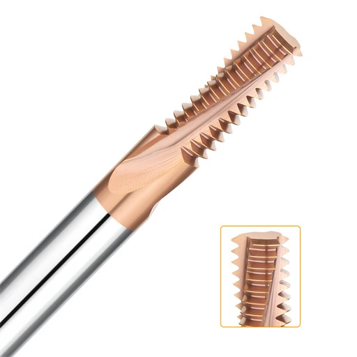
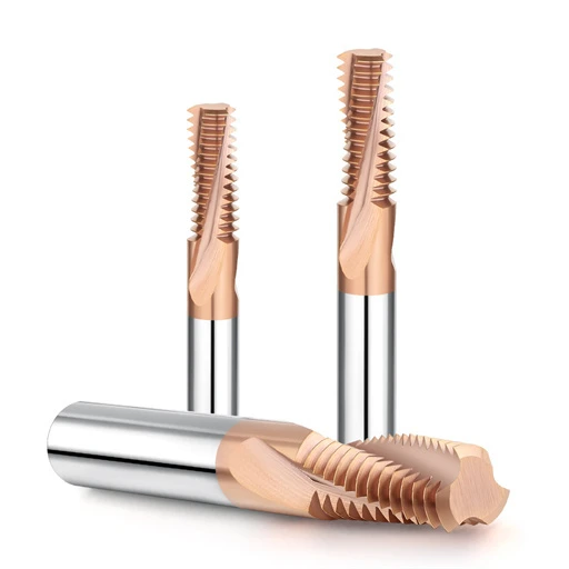
In these extreme conditions, you need a dedicated HRC65 micro thread mill. The key advantage is not just an extra coating layer. It is a ground-up redesign: beefed-up neck tapers, thicker solid core sections, and reinforced tooth backs. Trading away deep flutes dramatically boosts dynamic rigidity, keeping sub-micron deflection safely inside the elastic limit.
The Balancing Act for Micro-Diameter Tools: Optimizing Core Thickness for Small-Diameter Thread Mills to Ensure Both Chip Evacuation and Vibration Resistance
Balancing core thickness on M1.2 to M3 thread mills is a direct engineering trade-off. We tested standard 55% core cutters against dedicated 68% to 72% core designs on HRC 65 mold steel. High-speed cameras proved that standard tools flutter under cut, while a rigid small diameter thread mill dampens high-frequency chatter and delivers clean surface finishes.
Do not push core thickness past 80%, or shallow flutes will trap chips at the blind hole bottom. Our shop rule: for holes under 2D with strong air blasts, run a 70% core for maximum stiffness. Near 3D depth, trim the core cross-section by 3% to 5% to open chip space. Taking an extra radial pass is always better than packing flutes with swarf.
Minimize Overhang and Ensure High Concentricity: Keep the Radial Runout of Micro Thread Milling Cutters Below 3μm
Running micro-tools in worn ER11 collets or budget toolholders leads straight to broken cutters. While troubleshooting an aerospace shop in North America, we found an operator running nearly 12mm of overhang with 7μm of runout. For a micro thread milling cutter taking a 0.2mm radial depth of cut, that 7μm runout loads the entire cut onto a single tooth.
Tool clamping in hardened steel demands strict discipline. Keep your tool stickout within three times the neck diameter. Always use high-precision hydraulic chucks or premium micro-collet holders. Dial in your runout 1mm from the cutting edge and keep it under 3μm. Balancing cutting forces across all teeth is the only way to avoid sudden chipping.
Choosing Between Single-Tooth and Multi-Tooth Cutters
Catalogs love multi-tooth cutters because they finish a thread in one helical pass. However, our shop trials and production runs tell a different story. In HRC 65 materials at depths past 2D, multi-tooth cutters break far more often. Theoretical cycle-time savings mean nothing once an unexpected tool failure stops the spindle.
Multi-tooth tools engage along their full cutting length simultaneously. This spikes radial forces, bending the tool shank and causing severe taper or undersized pitch diameters down low. In contrast, a single-tooth small diameter thread mill cuts at one point at a time, slashing side forces. The extra few seconds per hole are well worth the zero-scrap reliability.

Machine Motion Control and Path Planning: Impact-Free Entry for Micro-Thread Milling in Hardened Steel
Machinists often rely on CAM-default helical entry paths when milling standard steels. However, micro thread milling hardened steel punishes every millisecond of abrupt machine acceleration. At HRC 65, the workpiece has zero give. If the cutter hits the wall with an acceleration spike, the fragile micro-teeth strike an unyielding barrier and chip instantly.
Always crank your look-ahead and high-precision contouring modes (like FANUC AICC II or HEIDENHAIN Cycle 32) to their highest settings. Your goal is continuous, shock-free tangential motion down to the micron. Smoothing the machine trajectory transforms heavy shock loads into gradual, steady forces that protect tiny cutting edges through the entire thread depth.
Avoid 90-Degree Direct Entry: How “Arc-In” and “Arc-Out” Eliminate Impact During Micro-Hole Threading
Plunging straight into the bore wall at 90 degrees causes immediate tool failure. While helping a Swiss watch-component moldmaker, we found their code jumping straight from a G01 linear move into a G02 arc. This created a blunt entry angle, spiking chip load from zero to maximum instantly. For a tiny cutter, this sudden impact hits like a sledgehammer.
The proven shop fix is a smooth, 180-degree tangential arc-in path. The tool center sweeps in along a semicircular spatial helix, letting chip thickness ramp up gently from zero to full engagement. Retract using the exact same 180-degree tangential arc-out motion. This path irons out transient cutting spikes and keeps entry forces well within safe limits.
Climb Milling and Tool Deflection Compensation: Predictive Algorithms to Eliminate Taper in Hardened Steel Threads
Always climb-mill your internal threads from the bottom up. Thin-to-thick chip formation limits work hardening and sheds friction heat away from the workpiece. However, cutting resistance from HRC 65 steel will inevitably deflect a slim tool shank. This creates an unwanted taper, leaving the bottom threads tight and causing no-go gauge failures.
Because perfect tool rigidity is physically impossible, program a gradual taper compensation in your macro code. We use a linear compensation model based on tool stickout. We gradually bias the interpolation radius outward by 3μm to 8μm as the micro thread milling cutter travels deeper. This simple programmatic taper offset holds strict 6H tolerances without trial-and-error guessing.
Relaxing Pilot Hole Tolerances in Practice: Reducing Load on Solid Carbide Micro Thread Mills by Increasing Pilot Hole Size by 5%
Standard shop handbooks specify pilot holes for 75% to 80% thread engagement. In HRC 65 steel, following that rule blindly destroys tools. High engagement packs excess stock into tiny thread roots, choking chip evacuation and crushing a delicate solid carbide micro thread mill. Given the extreme baseline strength of hardened steel, slightly lower thread depth still provides full holding power.
If the customer’s drawing permits, open the pilot hole diameter by 3% to 5%, targeting roughly 60% thread engagement. This creates vital breathing room for tiny chips to flush out. Plus important, it trims cutting forces on the delicate outer tooth corners by nearly a third. Making this practical concession is one of the easiest ways to eliminate broken tools in production.
Process Data Verification: Establishing Operational Limits for Micro Thread Milling Parameters
Many machinists simply copy the cutting feeds and speeds printed on the back of tool packaging. That shortcut might work in soft steels or 6061 aluminum, but running catalog limits in HRC 65 tool steel guarantees broken tools. Dialing in shop-proven micro thread milling parameters requires finding a narrow operating window between brittle tooth chipping and catastrophic friction rubbing.
Spindle speed discipline is our primary defense against sudden impact loads on micro-cutting edges. In HRC 65 steel, running even 10% past the safe surface footage generates extreme thermal spikes that rapidly peel tool coatings. Conversely, feeding too conservatively forces the teeth to burnish the surface, triggering severe work hardening. Locking down your verified speed and feed envelope is mandatory for continuous, lights-out threading.
Calculating Actual Cutting Speed (Vc) and Centerline Feed for Small-Diameter Thread Mills: Preventing Overload per Tooth
This is the most common programming trap we uncover during on-site shop audits. Programmers routinely take linear feed rates and plug them straight into internal helical interpolation cycles without internal curvature compensation. With a 1.0mm to 2.0mm small diameter thread mill, the tool center follows a much smaller radius than the internal bore profile. Without mathematical scaling, actual per-tooth chip load (fz) doubles or triples, snapping fragile teeth immediately.
In HRC 65 tool steel, keep your baseline surface footage (Vc) strictly within 25 to 45 m/min to manage edge heat. Cap your nominal per-tooth feed rate at 0.003 to 0.008 mm/tooth. Scale down your center feed rate (F_center) using your CNC controller’s tool-center point control or direct geometric bore-to-tool radius ratios. Capping actual perimeter load protects slim tools from unseen, fatal overloads.
Radial Multi-Pass Strategy: A 3-to-5-Pass Incremental Load-Reduction Schedule for HRC65 Hardened Steel
Never attempt to mill a full thread profile in HRC 65 steel in a single radial pass. Our shop trials showed that single-pass cuts in M1.6 threads broke cutters before finishing two pitches. By dividing the cut into four step-down passes, cutter life consistently exceeded 30 finished threaded holes. When tackling high-shear alloys, step-down radial passes are the only reliable way to reduce deflection.
We rely on an equal-area, 3-to-5-pass reduction sequence for ultra-hard metals. In a typical 4-pass cycle, pass one clears 45% of profile depth, pass two cuts 30%, pass three takes 15%, and the spring pass skims the final 10% (~0.015mm) to clean up deflection. Decreasing radial depth (ae) on each pass equalizes cutting forces per cycle, keeping your micro thread milling strategy stable and rigid.
Diagnosing Micro-Thread Milling via Chip Morphology: Inferring Cutting Temperature and Tool Wear from Fine Metallic Debris
When deep micro-holes cannot be inspected with an endoscope, chips in the swarf tray serve as your primary diagnostic tool. We assess a micro thread milling cutter by inspecting blown-out debris under high-intensity light and a 50x pocket loupe. Healthy shearing in HRC 65 steel yields bright silver or pale straw needle-flakes, proving that chips are carrying thermal energy away from the cut.
If chips look like dark brown or blue charred dust under magnification, stop the spindle immediately. That discoloration signals that cutting zone heat has breached the coating’s thermal barrier and caused micro-chipping. At that point, the cutter is grinding instead of shearing. Back down your surface footage before that dull edge snaps off deep inside a finished mold insert.
On-Machine Self-Inspection Checklist: Standard Operating Procedures (SOP) for Deploying Micro Thread Mills for Hardened Steel
Solid tooling geometry, tangential entry arcs, and layered passes mean nothing without rigid machine-side setup standards. In our field work across European and North American mold shops, well-engineered programs still fail on the first run due to simple setup oversights. A loose collet taper or poor chip evacuation quickly turns an expensive tool into scrap.
We urge shops to standardize their spindle preparation routines before mounting a dedicated micro thread mill for hardened steel. Ultrasonic-clean toolholder tapers, balance assemblies dynamically, and visually inspect early-pass spark formation. Rigorous setup checklists protect micro-tooling investments and give operators confidence during unattended production runs.
High-Pressure Air Evacuation and Nozzle Angle Calibration: Preventing Edge Chipping Caused by Re-Crushing Hardened Micro-Chips
Chips from HRC 65 steel are fine as dust, yet hard enough to chip oncoming teeth upon contact. In deep blind micro-bores without through-tool channels, external air blasts are your only chip clearing lifeline. Loose, flexible coolant nozzles aimed casually at the part face create entry vortices that trap chips inside, packing hole bottoms with abrasive grit.
If you are running blind holes deeper than 2.5D, switch to clean, dry air at 0.6 to 0.8 MPa using dual symmetrical nozzles. Mount nozzle tips within 15mm of the bore, pointing down at a 30° to 45° angle relative to the hole centerline. This creates a focused micro-cyclone that draws swarf up and out, preventing teeth from recutting chips inside narrow thread roots.
Optimizing CNC Cycle Times: Balancing Machining Efficiency Under Extreme Conditions with Tool Life Stability
Rushing cycle times on hardened workpieces is an expensive habit. Adding an extra radial pass adds 8 to 12 seconds per hole, but it frequently boosts tool life from 15 holes to more than 40. Across a multi-cavity mold, sustained tool life and zero scrap far outweigh minor cycle time gains. We always optimize programs for reliable, hands-off tool life across entire production batches.
If you struggle with erratic pitch diameters or middle-of-the-night tool failures, try adding a light spring pass, or adjust axial step intervals to smooth spindle loads. Machine rigidity and batch material hardness vary from shop to shop. If you are wrestling with tough micro-thread prints, unusual tool steels, or sudden tool breakage, send us your part prints and machining parameters. We will help you dial in a bulletproof, production-ready solution.