
During the first-article inspection of high-precision aluminum valve blocks for a Tier 1 German automotive supplier, the threads failed inspection. Although drawings specified a metric 6H class, the no-go gauge would not start at the hole entry, while the go gauge jammed near the bottom. The machinist immediately tweaked the tool radius compensation (D-value) in the CNC controller. This allowed the go gauge to seat, but the no-go gauge blew completely through—scrapping the entire production batch.
This costly failure is a common service call in our customer support logs. When confronted with distorted pitch diameters, taper, or gauge binding, shops routinely blame the dimensional quality of the solid carbide thread milling cutters. However, after analyzing NC programs, checking dynamic holder balance, and measuring actual stickout, we consistently find the root cause elsewhere in the setup.
Thread milling relies on three-axis simultaneous helical interpolation. A minor spike in radial cutting force or confusing tool-centerline feed with cutting-edge perimeter feed quickly ruins part tolerances. When running precision thread milling in deep blind holes or tough alloys, tool deflection and recut chips create cumulative errors. These dimensional shifts cannot be fixed simply by adjusting a wear offset at the control panel.
We compiled this guide from over a decade of hands-on machining and tooling support to address recurring dimensional failures. Our goal is to isolate the real engineering variables that hurt thread milling accuracy. Is an unworn thread mill sitting in your machine right now, failing thread gauges no matter how many offsets you enter?
The Reality of “Tool Push-off” with Solid Carbide Thread Milling Cutters in Deep Holes and Difficult-to-Machine Materials
When visiting customer shops across the US and Europe, we constantly hear operators complain that their cutters lack rigidity. In reality, cutting open the scrap part shows that the tool did not fail—the machining strategy did. As overhang grows, radial forces acting on the tool tip follow cantilever beam mechanics, pushing the cutter off its programmed path.
Machining heat-resistant alloys or hardened mold steels makes this deflection obvious. The tool cuts a clean, in-spec thread at the hole entrance, but the pitch diameter shrinks as the cutter travels deeper. The go gauge ends up seizing just a few turns in. This is rarely a machine pitch error; it is uncompensated elastic deflection caused by excessive tool load, causing the solid carbide thread milling cutters to deflect away from the wall.
Tapered Threads and Thread Depth Distortion Caused by Mismatched Tool Size and Overhang
Many programmers default to the largest cutter that fits the hole, assuming maximum shank diameter guarantees stability. While troubleshooting an M14×1.5 port on a hydraulic block, we found a customer using an oversized cutter body with barely any wall clearance. Chip evacuation space was completely choked. Packed chips wedged against the hole floor and pushed the tool off-center, producing a 0.04mm taper and distorted thread depth.
This is a textbook mistake in thread mill sizing. When cutter diameter is too close to the minor diameter, the cutting arc of engagement jumps dramatically, which spikes radial cutting resistance. Conversely, dropping tool diameter too far to clear deep holes leads to excessive bending under load. We recommend keeping the cutter diameter within 60% to 70% of the minor thread diameter to ensure adequate chip clearance and prevent taper.
Selecting High-Rigidity Solid Carbide Thread Milling Cutters: Why Reduce the Shank Diameter for Overhangs Exceeding 3D?
Once the thread depth-to-diameter ratio exceeds 3D, cutting dynamics change entirely. Our shop tests confirm that increasing the overhang ratio from 2D to 3.5D multiplies tool deflection under identical cutting loads. Using a standard straight-shank tool under these conditions creates a major hazard: the non-cutting shank rubs against the freshly cut crests near the top of the hole, triggering high-frequency chatter.
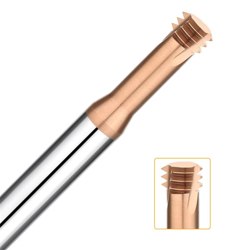
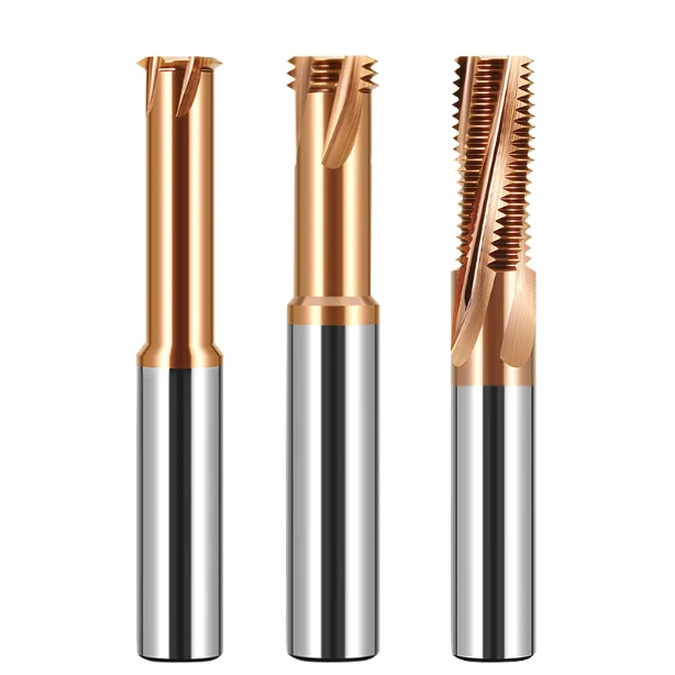
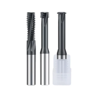
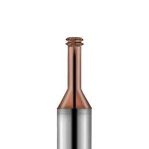
For deep-hole threads, we prioritize solid carbide thread milling cutters engineered with a relieved neck. Reducing the neck diameter behind the cutting flutes slightly lowers local cross-sectional area, but it completely eliminates shank rubbing. It also opens up a clear exit path for high-pressure coolant and chips. Accepting this minor trade-off in nominal mass yields far better dynamic stability and dimensional consistency.
The Fatal Impact of Tool Runout on Precision Thread Milling: What Happens When Radial Runout at the Tool Tip Exceeds 0.005mm?
Customers frequently send us used cutters with premature, uneven tooth wear: one flute is chipped flat while the remaining flutes look brand new. In almost every case, measuring the tool tip in their holder reveals radial runout above 0.012mm. In precision thread milling, this runout is fatal because every tooth must generate the exact thread form along a synchronized helical path.
When radial runout exceeds 0.005mm, the entire chip load shifts onto a single cutting edge. That overloaded tooth chips prematurely, tearing the thread flanks and cutting an out-of-round, polygonal pitch diameter. In our technical audits, we never diagnose thread errors until we verify holder runout below 0.003mm using hydraulic chucks or shrink-fit systems. If tool runout is out of spec, adjusting radius offsets in your CNC program is a waste of time.
Thread Tolerances and Geometric Distortion: Decoding Thread Size Tolerance and Thread Profile Deviations
In our technical support calls, we frequently see operators shaking their heads over failed go/no-go gauges. Even when the pre-tap hole diameter measures true and the thread angle checks out, the internal thread still fails inspection. This issue is rarely a simple scale error across the hole. Instead, high cutting pressure during helical interpolation distorts the entire thread profile.
Sectioning the workpiece under an optical comparator makes this deviation obvious. The symmetrical 60-degree flank angle shifts toward the trailing edge, while the root radius shrinks. This cutting force imbalance pushes the part outside the specified thread size tolerance. You end up trapped in a common inspection dilemma: the pitch diameter passes, but the crests bind; or the crests clear, but flank clearances fail.
The “No-Go Passes, Go Fails” Phenomenon at the Bottom of Blind Holes: Uneven Cutting Loads in Thread Milling
Machining blind holes often creates a frustrating defect: the thread gauge passes at the top, but fails deep down. The go gauge jams halfway, while the no-go gauge starts turning freely at the bottom. We saw this firsthand at a hydraulic valve shop. Operators had programmed the tool too close to the floor, trapping metal chips around the lead teeth.
Many machinists mistake this for tap-style hole shrinkage. Under tight thread milling tolerance bands, it is actually “reverse cutting deflection.” The lead tooth takes both radial load and axial backpressure from packed chips, grinding the bottom crests undersize. We recommend leaving at least 1.5 pitches of floor clearance, or programming an upward climb-milling path to relieve bottom-hole stress.
The Direct Impact of Actual Cutting Radius Deviation and CNC Wear Compensation (D-value) Adjustments on Thread Milling Accuracy
When a plug gauge binds, most operators instinctively trim 0.01 mm off the D-value wear offset. Yet dialling in a negative 0.02 mm offset often yields almost no change on the pitch micrometer. Instead, you see shiny, burnished witness marks pressed into the thread flanks.
This happens when you confuse static tool radius with dynamic cutting radius, undermining true thread milling accuracy. Deflection under load keeps the actual cutter path smaller than the programmed path. Forcing dimensions by cranking down the D-offset causes rubbing, micro-chipping, and flank distortion. Always map the tool’s true deflection first, then use multi-pass offsets rather than blindly guessing at D-values.
Thread Misalignment and Cumulative Pitch Error: Troubleshooting Arc-in/out Trajectories and Helical Interpolation Synchronization
A particularly frustrating scrap event happens when a thread looks mirror-smooth, but the go gauge seizes after two turns. Forcing it instantly galls the flanks. Machinists usually suspect Z-axis pitch error or machine backlash. In our field inspections with laser interferometers, the problem almost always traces back to the arc-in and arc-out toolpaths.
Entering with a tight lead-in arc causes servo acceleration lag during 3-axis interpolation. That lag creates a microscopic step in the thread lead right at the entry point, destroying the pitch consistency needed for precision thread milling. We program smooth 90-to-180-degree tangential lead-in arcs. This ensures all three axes reach synchronized feed rates before the flutes touch raw stock.
Practical Machining of Ultra-Hard Materials: Challenges in Thread Milling HRC60 Hardened Steel and High-Hardness Die Steels
Milling threads into quenched, fully hardened steel pushes cutting tools to their thermal and physical limits. We often troubleshoot die-casting and stamping shops where soft-machining went smoothly, but tool reliability collapsed after vacuum hardening. The hardness spike turns stable setups into scrap generators within minutes.
Hardened steels have massive yield strength, producing brittle chips that hammer the cutting edge. 시도 중 thread milling HRC60 hardened steel with the heavy feed rates used on pre-hardened steels causes instant chatter and micro-thermal shocks. The thread pitch diameter wanders erratically, surface finish degrades, and carbide flutes break down long before expected tool life is reached.
Machining Quenched Molds and Heat-Treated Parts: Micro-chipping and Thread Crest Deformation in HRC60 Thread Milling
At an automotive stamping supplier running vacuum-hardened die inserts above 60 HRC, internal threads consistently failed gauge tests. Under a microscope, the thread crests looked torn and jagged, causing no-go gauges to bind right at the hole entrance.
This damage stems from extreme mechanical shock during HRC60 thread milling. The high-hardness core chips the fragile edge on initial contact. Once that sharp edge is lost, cutting turns into heavy friction, crushing the brittle crests instead of shearing them. We solved this by using radius-honed edges: sacrificing slight initial free-cutting sharpness for the edge strength needed to survive high-impact entry.
The Hardness Threshold for Thread Milling HRC60 Hardened Steel: Why Shift from Single-Tool Multi-Pass Machining to a Roughing-Finishing Strategy?
Once core hardness crosses 58 to 60 HRC, standard single-tool rough-to-finish strategies break down. Operators often run three passes with one cutter: rough, semi-finish, and a light spring pass. On hardened steel, that final light cut cannot bite into the wall. The tool rubs, work-hardens the surface, and pushes the pitch diameter even tighter.
When handling thread milling HRC60 hardened steel, we separate roughing from finishing across two distinct tools. A tough-substrate cutter hogs out roughly 80% of the material first. Then, an ultra-fine grain finishing tool makes a single, high-speed sizing pass. Bypassing the glazed, work-hardened zone ensures consistent pitch diameter, symmetrical flank angles, and predictable tool life.
Abrupt Changes in Thread Profile Dimensions Due to Coating Delamination: Determining Tool-Change Thresholds Based on Wear-Resistant Coating Failure and Flank Wear
In hardened mold steel, operators often ask why twenty holes pass gauge inspection, but the twenty-first scraps the block without warning. Our lab checks show the culprit is sudden coating delamination. Friction in dry or MQL cuts spikes interface temperatures past 1,000°C, causing the nano-coating to flake away under thermal fatigue.
This sudden wear spike ruins the flank profile stability demanded by precision thread milling. On ultra-hard materials, never wait for an audible squeal or a jammed gauge to pull the cutter. Keep flank wear bands within a strict micron limit, and set a hard tool-life limit by total holes cut to prevent unexpected scrap.
Imbalance Between Cutting Parameters and Cutting Forces: Common Misconceptions in Thread Milling Speed and Feed Rate Settings
When troubleshooting thread dimension errors on the shop floor, we often find programmers applying standard end-milling logic. Thread milling is a multi-axis helical routine with a wide contact arc along the bore wall. This engagement generates complex radial and axial vectors rather than straightforward linear forces. Trusting raw catalog numbers without accounting for bore geometry quickly ruins your cut.
Losing the balance between feed and surface footage rarely damages the tool first. Instead, it ruins pitch diameter consistency and flank symmetry. Uneven tooth loads cause chatter, poor surface finishes, and tapered threads. Dialing in the correct 나사 밀링 절삭 속도 alongside real edge feed rates is the only way to eliminate these dynamic dimensional errors.
The Cutting Speed Trap Behind Pitch Tolerance Failures: Thermal Deformation Caused by Excessive Thread Milling Speeds
While milling deep threads in aerospace titanium, a client maxed out spindle RPM to shave cycle seconds. Fresh off the table, the parts passed go/no-go plug gauges. Hours later, after cooling down in the quality lab, CMM inspection revealed out-of-spec pitch diameters and stretched lead errors. The crew even suspected the metrology lab’s AC had failed.
This is a classic thermal trap caused by excessive thread milling cutting speed. Heat expands both the workpiece material and the tool shank during the cut, distorting the programmed helical pitch. When running heat-sensitive or high-temp alloys, dropping surface footage by 15% to 20% stabilizes thermal growth. The part stays cold, and threads measure true once room temperature stabilizes.
Calculation Errors Between Tool Center Feed and Outer Circumferential Feed: Leading to Excessive Feed-per-Tooth and Thread Oversizing
This is the most common programming mistake we catch during field audits. A programmer keys in a modest 0.05 mm feed-per-tooth in CAM, but the post processor outputs standard Tool Center Point (TCP) motion. Inside an internal bore, the tool path compresses, making the outer cutting edge move much faster than the centerline.
That uncorrected arc feed spikes the real chip load, deflecting the cutter body and blowing past your target thread size tolerance. In small bores, actual edge feed can double your intended value, forcing the cutter into an oversized cut. Always verify your machine’s internal radius feed compensation (like G41/G42 feed adjustments) so the cutting edge sees its true, programmed chip thickness.
Secondary Cutting and Thread-Flank Scoring Due to Poor Chip Evacuation: The Role of High-Pressure Through-Tool Coolant in Ensuring Dimensional Stability in Precision Thread Milling
When running blind holes in stainless or nickel alloys, shops often see torn thread flanks and scored root radiuses. The tool edge may look completely sharp, yet the chips exiting the hole look like crushed metal dust. Trapped chips recirculate in the tight radial clearance, getting re-cut and abrading finished thread walls.
In precision thread milling, chip re-cutting destroys dimensional accuracy faster than standard flank wear. Trapped metal wedges against the flutes, driving cutter deflection and gouging flanks. External coolant flood nozzles cannot punch past the swirling air barrier in deep holes. High-pressure through-spindle coolant or pulsed through-air is mandatory to blast swarf up and out of the cavity.
Field Troubleshooting Guide: Addressing Dimensional Deviations and Accuracy Issues in Thread Milling
Thread dimensional drift is rarely an isolated accident; it is the predictable result of changing cutting pressures and thermal shifts. When parts fail inspection, never start changing speeds, feeds, or offsets at random. Guesswork burns machine hours and piles up scrap. You need a structured, root-cause checklist to isolate errors quickly.
By tracking stick-out deflection, interpolation lag, thermal growth, and effective chip load, you can pinpoint the exact cause of dimensional errors. When your shop-floor thread mill cutters produce tapered threads or sticky gauges, running through this methodical checklist brings parts back into tolerance without stalling production.
Compensation Strategies for Thread Milling Accuracy
Orders for Western aerospace or medical sectors regularly specify tight-tolerance profiles like UNJ or Metric 4H. These standards demand strict control over root radiuses and tight pitch diameter windows. Under such tight limits, a tiny fraction of tool deflection will fail an optical comparator inspection immediately.
If you are struggling to pass strict aerospace callouts, split your cut into three stages: roughing, flank cleanup, and final sizing. To preserve thread milling accuracy, apply a small lead pre-compensation on the entry arc to absorb servo delay at the lead-in point. If you are dealing with challenging pre-plate dimensions or strict controlled-root specs, mapping out your actual cutting forces early will save expensive trial cuts.
First-Article Inspection on the Shop Floor: A Closed-Loop Calibration Method Using the Three-Wire Technique, Thread Gauges, and Tolerance Control
Many operators rely entirely on go/no-go plug gauges for sign-off: if it threads in and stops correctly, they hit cycle start. But plug gauges only provide a qualitative pass/fail result. They cannot tell you if your pitch diameter sits near the high, middle, or low end of your limits. As the tool wears, your parts quietly drift into the scrap bin.
If you are running production batches of expensive forgings or castings, you can use a closed-loop first-article routine to lock in dimensions. Measure the rough hole with a bore gauge, verify external tool pitch geometry with thread wires, and use gauges only for final verification. Setting your initial cut toward the upper limit of your thread size tolerance leaves plenty of room for normal tool wear across the shift.
Standardized Operating Procedures for Extending the Lifespan and Maintaining Dimensional Consistency of Thread Mill Cutters
Holding identical thread tolerances from part one to part five hundred comes down to disciplined setup habits, not operator guesswork. In our customer integration audits, sudden size jumps usually trace back to chips inside the collet, fluctuating air pressure, or running cutters past their fatigue limits.
If you fight inconsistent thread sizes across shifts, tighten your workholding and tool-maintenance standards. Clean toolholder tapers with dedicated wipers, torque collet nuts to exact specifications, and track flute contact hours to trigger planned tool swaps. Consistent maintenance protects your thread mill cutters from sudden wear spikes. If your team is running into persistent dimensional drift on a specific part or tough alloy, feel free to share your prints, tooling setup, and cutting parameters so we can work through the fix together.