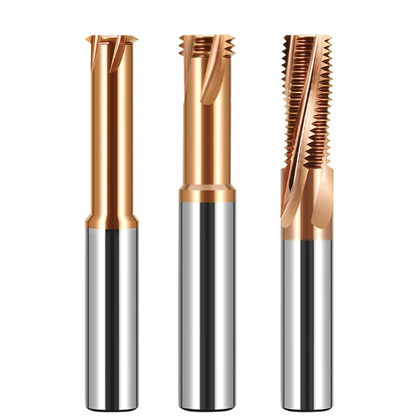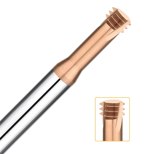

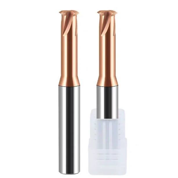
While helping a German tooling customer troubleshoot slider inserts hardened to HRC63–65, we ran into an all-too-familiar headache. The batch of M6 internal threads passed every coordinate measuring machine (CMM) check, optical inspection, and go/no-go gauge test. However, the thread flanks consistently missed the target Ra 0.4 specification. Under a microscope, the thread walls showed cloudy white burnish tracks, periodic chatter lines, and microscopic micro-tears invisible to the naked eye.
This specific poor thread surface quality is never just a simple machine operator error. Over the past decade of supporting machining facilities across North America and Europe, we have seen this exact scenario repeat itself on multiple shop floors. When tackling D2 thread milling or similar hardened tool steels, most machinists immediately blame poor coating adhesion or an incorrect program feed.
In steel hardened to HRC65, the grain structure consists almost entirely of tempered martensite and hard carbide clusters. The metal-cutting mechanism shifts away from plastic shearing toward brittle micro-fracture and heavy elastic strain. Achieving a superior thread mill surface finish depends on more than just swapping tools. Variables like thread mill geometry, machine dynamic compliance during circular interpolation, and an extra 3 µm of runout all directly print onto the cut surface.
When cutting heat, tool deflection, and crushed micro-chips fall out of balance, even a top-tier cnc thread milling bit leaves torn, ragged threads behind. If your dimensions are in spec and the tool isn’t chipping, but the surface finish stays rough, what should you tweak first: the thread mill speed, or your entire radial multi-pass toolpath?
The Physical Limits of High Hardness Steel Thread Machining and the Trap of Machine Rigidity
When cutting steels above HRC60, leave standard machining assumptions behind. You cannot form thread flanks smoothly as you would in pre-hardened alloys. Yield strength is immense, multiplying cutting resistance several times over quenched-and-tempered steels. Thread milling under these conditions acts as micro-impact machining across an extremely small contact width. Surging radial forces instantly expose every mechanical clearance in your machine tool.
Many operators fail to consider spindle servo rigidity during light radial cuts. In high hardness steel thread machining, your machine bed damping, guideway preloads, and ball-screw backlash set the baseline for stability. If dynamic rigidity cannot absorb the initial shock when the tooth bites, high-frequency chatter ensues. Even with an ultra-hard carbide substrate, your thread flanks will turn out dull and scuffed.
Poor Thread Surface Quality in D2 Steel Thread Milling: Insufficient Rigidity and Radial Tool Deflection
Hard carbides in cold-work tool steels create severe tool deflection. During customer trials for D2 thread milling, deep-hole thread finishes routinely degraded toward the hole bottom. Hardness at HRC60–65 magnifies tool overhang flex under heavy cutting resistance. The tool springs back when cutting pressures fluctuate during helical interpolation. This cyclical bouncing leaves alternating wavy bands on the flanks, producing poor thread surface quality.
We suggest avoiding full-profile, single-pass cuts entirely on hardened steels. If you must run this setup on a standard vertical machining center, restrict tool overhang to 2.5×D or use tapered-neck shanks. Break the thread depth into two or three radial passes. While radial multi-pass machining adds minimal cycle time, it slashes cutting pressure. Lower cutting force eliminates tool rubbing on return paths, restoring flank smoothness.
The Critical Impact of Tool Holder Runout on Thread Milling Surface Quality: Why Exceeding 3μm Always Leads to Chatter Marks
Machinists often ask why runout must stay below 3μm when 8μm to 10μm works fine for milling softer steels. The physics at HRC65 are unforgiving. Chip load per tooth is tiny, typically between 0.008 mm and 0.02 mm. A 5μm total runout means only one or two teeth take the entire cutting load. The remaining flutes merely rub the surface, creating cyclic shock loads that ruin thread milling surface quality.
When diagnosing microscopic chatter marks, our first step is checking tool-tip runout with a dial indicator. Above 3μm runout in HRC65 materials, fish-scale chatter marks appear on the flanks immediately. Individual teeth soon develop micro-chipping from load spikes. Replace standard ER collet chucks with hydraulic holders, shrink-fit systems, or high-precision mechanical clamping. Equal tooth engagement is essential to prevent thread flank chatter.
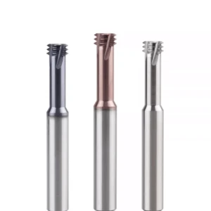
Thread Mill Geometry Tailored for Hardened Steel: Why General-Purpose Cutters Fail
We often see shop operators grab general-purpose tools to cut HRC65 parts. The result is always disappointing: 따분한, sandpaper-like thread flanks after just one part. Standard tooling relies on positive rake angles and deep flutes designed for ductile steels. In hardened alloys, those thin cutting edges quickly collapse under extreme contact stresses.
Cutting HRC65 steel exerts intense normal forces on the tool edge. Standard geometries lack the core strength needed to prevent microscopic edge chipping. We redesign our tooling around a fortified cross-section, shallower flutes, and reinforced wedge angles. Optimizing this dedicated thread mill geometry replaces fragile shearing action with rigid compressive cutting that withstands tempered martensite.
Thread Mill Geometry for Ultra-Hard Steel: Negative Rake, Micro-Chamfers, and Variable Helix
Hardness past HRC60 shifts the cutting dynamic toward controlled micro-fracture. We replace standard positive rakes with a negative rake angle between -5° and -8°. Along the cutting edge, we hone a micro-chamfer 0.02 mm to 0.03 mm wide. This negative land redirects dangerous tensile stresses into stable compressive forces, suppressing microscopic tearing on the thread wall.
We also incorporate unequal helix angles and variable pitch into the tool body. When flutes engage the hardened bore at asymmetrical intervals, they disrupt harmonic resonance. This geometry eliminates high-frequency chatter during circular interpolation. As a result, the optimized thread mill geometry stabilizes tool deflection and refines thread flank smoothness.
Coating Thickness and Edge Honing: Preventing Chipping on the Thread Cutting Tool
Razor-sharp edges often cause early micro-chipping in hardened alloys. Under a microscope, an unhoned ground edge looks like a jagged saw. The moment it hits HRC65 steel, raw micro-burrs snap off, leaving micro-notches that score the workpiece. For every specialized 실 절단 도구, we hone a controlled 4 μm to 8 μm edge radius to guarantee clean, streak-free flank engagement.
Coating thickness requires strict process control. High-aluminum AlTiN and AlCrN coatings provide exceptional heat and wear resistance. Yet coatings thicker than 3.5 μm build up internal stresses that lead to premature delamination. We target a thin 2 μm layer on the honed carbide substrate. This balance prevents flaking, resists abrasive wear, and delivers a clean metallic luster.
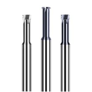
Balancing Cutting Speed and Feed: Optimizing Thread Mill Speed to Prevent Burning and Chatter
Machining HRC65 steel leaves virtually zero margin for error. Feed changes as small as 10% can make or break the cut. Underfeeding causes rubbing, tool burnishing, and rapid work hardening. Overfeeding spikes deflection forces, causing rapid chatter or broken teeth. Excess friction also builds heat in milliseconds, degrading protective coatings.
When tuning cycle times, never rely on a single cutting variable alone. You must balance the thread mill speed against true chip thickness. The cutting teeth must bite deep enough to bypass work-hardened zones without exceeding shank yield strength. Hitting this target requires balancing thermal dissipation against the machine’s vibration threshold.
Pinpointing the Thread Milling Cutting Speed (Vc): Avoiding Built-Up Edge vs. Flank Scoring
When thread flanks look dull or dark, machinists often drop the spindle speed too low. Running below 20 m/min stops the tool from cutting cleanly, causing the edge to burnish and plow the surface into rough, gray-white scars. Conversely, pushing past 70 m/min overheats the tool, oxidizing coatings and triggering microscopic edge build-up that scores the flanks.
We suggest setting the initial 나사 밀링 절삭 속도 between 35 and 50 m/min. This window creates enough thermal softening ahead of the shear zone without compromising substrate red hardness. Rigid machining centers and shrink-fit tool holders can support the higher end of this range. If machine rigidity is marginal, run closer to 35 m/min to protect coating life.
Feed Rate Correction in Thread Milling: Why Overlooking Arc Compensation Tears Flank Surfaces
CAM programmers frequently forget that internal thread milling follows a small inner arc, not a straight path. The outer cutting tips travel a much longer distance than the tool centerline. Unless the CNC control recalculates this geometry, actual cutting loads on each tooth jump two to three times past the programmed feed rate.
This sudden load surge deflects the tool and tears into the tempered martensite. When running a cnc thread milling bit, always use internal arc feed compensation in your post-processor. You can also calculate feed manually with the factor: (Hole Diameter – Tool Diameter) / Hole Diameter. Keeping true chip load around 0.005 mm to 0.015 mm per tooth prevents edge pulling and ragged surfaces.
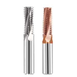
Toolpath Strategy and Process Planning: Eliminating Engagement Marks and Poor Thread Surface Quality
In HRC65 steel, flawed toolpaths quickly ruin thread walls despite using the best carbide cutters. We frequently see shops spend hours swapping holders and adjusting tool offsets without examining CAM-generated entry arcs. Threading at extreme hardness demands steady-state cutting forces. Any sudden spike in chip load causes the tool to deflect, leaving chatter steps across the flank.
Sudden feed accelerations and sharp radial entries trigger severe tool spring-back during helical interpolation. This elastic rebound leaves visible step marks and gouges, leading to poor thread surface quality. Process planning must follow three rules: gradual entry, constant tool load, and smooth exit. A continuous sliding cut prevents shock loading and protects the thread wall from tearing.
Radial Multipass Strategy: Precision Hole Sizing and Passes to Boost Thread Mill Surface Finish
Single-pass full-depth cutting in HRC65 alloys is an invitation to tool failure. Heavy radial engagement spikes side forces, heating the workpiece profile rapidly. We recommend a radial multi-pass routine: rough out 70% to 80% of the thread profile, then finish the remaining stock. Running a final spring pass without radial offset cleans up microscopic crests, dramatically improving the thread mill surface finish.
Do not overlook pre-hole quality before threading. Hard drilling or boring often leaves a glazed, work-hardened surface with taper or roundness errors. When the thread mill enters an uneven bore, radial forces fluctuate wildly. Clean the pre-machined hole with a rigid 엔드 밀 before threading. High bore roundness distributes radial cutting forces evenly across all passes, delivering mirror-like flanks.
Entry and Exit Strategy: Why 90-Degree Linear Moves Ruin Thread Milling Surface Finish
Direct 90-degree straight-line entry causes deep gouges at the thread start point. Striking the hardened wall head-on spikes the cut width instantly from zero to maximum. The tool flexes backward, stores elastic energy, and bites aggressively into the bore as interpolation starts. This rapid deflection causes micro-chipping and permanently degrades your local thread milling surface finish.
We recommend a 180-degree semicircular entry arc or an Archimedean spiral move instead. A tangential entry eases the cutting edges into the wall, letting cutting loads build gradually. The exit path should follow a matching tangential sweep. Spring-back then occurs in free space rather than against the workpiece. Switching to smooth arc moves completely removes witness lines and entry notches.
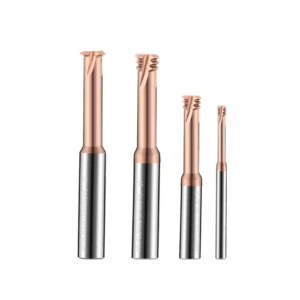
Coolant, Lubrication, and Chip Evacuation: Avoiding Chip Recutting in HRC65 Steels
Chip evacuation makes or breaks thread milling in HRC65 alloys. Even with optimal tool geometry and rigid setups, a few trapped chips will destroy the thread finish instantly. Hardened steel chips do not curl into soft ribbons. Instead, they form razor-sharp, ultra-hard fragments that crush easily under tool pressure.
Trapped chips become caught between the tool clearance face and the finished thread wall. This causes severe secondary cutting, grinding into the flank like an abrasive compound and ruining the metallic sheen. Proper fluid dynamics must clear particles within milliseconds. Your air or fluid flow must synchronize with tool motion to keep the cut zone clear.
Air Blast, MQL, or High-Pressure Coolant? Chip Damage to Thread Milling Surface Quality
Flooding HRC65 steel with low-pressure emulsion often does more harm than good. High friction heat combined with flood coolant creates severe thermal cycling on the cutting edges. This thermal fatigue rapidly cracks PVD coatings and chips sharp flutes. Trapped coolant also turns hard particles into an abrasive slurry, degrading thread milling surface quality.
If you rely on external nozzles, switch to chilled dry air using a cold-air vortex gun. Chilled air blasts fragments out while avoiding thermal shock. If you run MQL, push the delivery pressure high. High air volume evacuates chips while micro-droplets create an extreme-pressure boundary film. For machines with 70-bar through-spindle systems, run internal-coolant tools to flush blind holes.
Blind-Hole Chip Evacuation: Stopping CNC Thread Milling Bit Damage from Chip Crushing
Blind holes deeper than 2×D trap chips easily due to gravity and narrow flute channels. When driving a cnc thread milling bit from the bottom up in climb mode, swirling air lifts trapped chips from the bottom. These loose particles get caught between the cutting teeth and finished thread flanks, causing uncontrollable pitting and dull streaks.
If you machine deep blind holes without relief grooves, try top-down climb milling instead. The downward air stream forces chips into the bottom of the bore ahead of the cut, preventing scratches on finished threads. If you must run bottom-to-top toolpaths, add a brief dwell with a high-pressure air blast between radial passes. Clearing loose particles before each pass protects the flanks.