Skip to content


In CNC precision machining, T-slot cutters are specialized high-efficiency tools designed for machining T-slot structures. These cutters are widely used in machine tool worktables, fixture systems, mold structures, and automated equipment. Typically paired with vertical machining centers or CNC milling machines, T-slot cutters mill laterally extending grooves in workpieces to accommodate slides, positioning components, or clamping systems.
Compared to traditional end mills, T-slot end mills feature a unique neck and head design that allows them to penetrate deep into narrow slots while cutting both the sides and the bottom simultaneously. These cutters are essential for machining complex internal grooves. Common types include solid carbide T-slot cutters, welded cutters, and high-strength indexable cutters. The choice of tool directly affects cutting efficiency, surface quality, and tool life.
In practice, engineers must carefully consider factors such as workpiece material, slot width, cutting depth, and machine rigidity when selecting the appropriate T-slot milling cutter or T-slot cutting tool. Proper cutting path planning and selecting the right feed rates and spindle speeds improve milling efficiency and reduce the risk of premature tool wear and breakage.
This article provides a systematic analysis of the structure, machining methods, and application techniques of T-slot milling cutters, offering a deep understanding of their operating principles and selection strategies in CNC milling. It also includes practical process optimization recommendations for more efficient and reliable T-slot machining solutions.
Introduction to T-slot Milling Cutters: Structure and Function
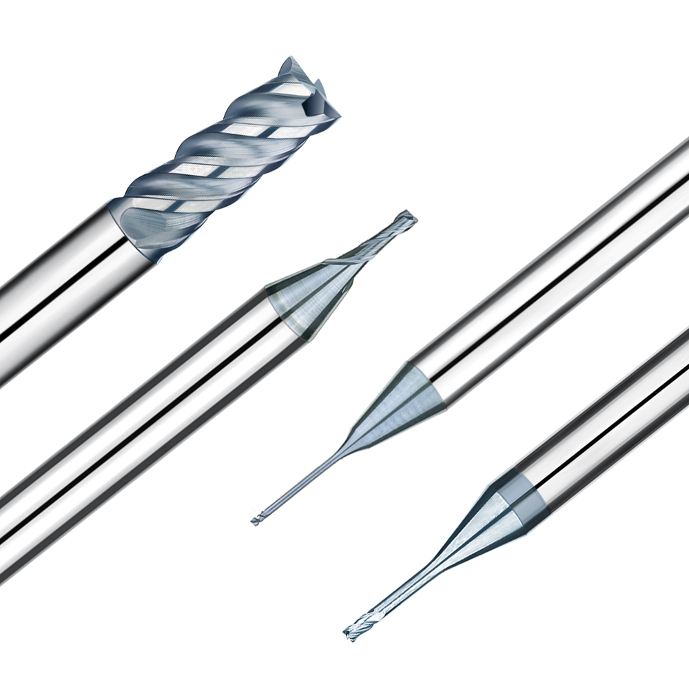
In CNC milling, T-slot milling cutters are specialized tools for machining T-slot structures, featuring unique geometries tailored for both side cutting and downcutting. Because T-slots are typically located below the workpiece surface, these cutters must combine excellent lateral cutting ability with the capacity to machine the slot bottom. This makes their design more complex than standard end mills.
What Is a T-slot Milling Cutter?
A typical T-slot milling cutter consists of a narrow neck and a wide head. The head’s outer edge has multiple cutting teeth, enabling simultaneous milling of the slot bottom and finishing of the slot walls. The long neck facilitates deep lateral cutting into the workpiece. The structure generally includes a straight or tapered shank, a neck transition zone, and a wide head. The head diameter determines the bottom slot width, while the neck diameter influences feed path clearance.
T-slots are commonly used in machine tool table clamping slots, mold base slide guides, and automated fixture positioning slots. These applications demand tight control of slot width, tolerance, and machining efficiency, placing higher requirements on tool rigidity, wear resistance, and compatibility.
Common Types of T-Slot Milling Cutters
Based on construction, T-slot milling cutters mainly fall into two categories:
-
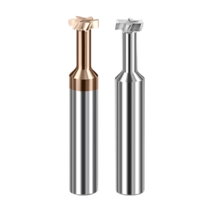
Integrated T-slot milling cutters: The cutter body and head form a single solid piece, offering high rigidity and machining accuracy. These cutters are ideal for deep slots or precision molds where coaxiality is critical.
-
Replaceable-head T-slot cutters: The cutter head is welded or threaded onto the body, suitable for high-volume roughing or applications requiring frequent cutter head replacement, reducing costs and extending toolholder life.
Based on material, the main options are:
-
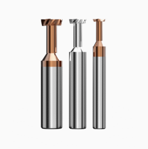
HSS T-slot cutters: Offer excellent toughness and adaptability, ideal for medium- and low-speed milling of common steel and aluminum parts, providing good cost-effectiveness.
-
Carbide T-slot milling cutters: Made from ultra-fine-grain carbide, offering superior wear resistance and thermal stability. These cutters excel in high-speed finishing of hard materials such as quenched and tempered steels and stainless steel.
Tool type influences cutting path planning, cooling methods, and cutting techniques. Engineers should select tools based on specific applications, equipment capabilities, and material properties to optimize machining efficiency and tool longevity.

The Difference Between T-Slot Mills and T-Slot End Mills
In CNC milling, T-slot mills and T-slot end mills are often confused, but they differ significantly in structure, machining methods, and use cases. Understanding these differences is crucial to improving machining efficiency, minimizing tool wear, and avoiding interference.
Definition and Applications of T-slot End Mills
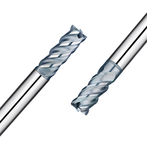
T-slot end mills are variants of end mills designed specifically for T-slot or undercut groove machining. Unlike flat-bottom end mills, T-slot end mills usually have shorter shanks and wider cutter heads, making them ideal for sidewall expansion and transverse milling following pre-grooving.
They are commonly used for roughing T-slots, forming mold slide grooves, and machining fixture guides. Typically one-piece with multi-tooth heads, T-slot end mills provide stable cutting forces at moderate depths of cut. Their geometry suits tight machining paths or space-limited areas—for example, expanding a pre-milled U-groove into a “T” profile.
Thanks to their versatility and rigidity, T-slot end mills are suitable alternatives to T-slot cutters for sidewall undercutting and rough machining, especially when machining strength requirements are moderate and space is limited.
Which Tool Best Suits Your Machining Needs?
Selecting between T-slot cutters and T-slot end mills depends on several factors:
-
Material type:
-
For medium-hard steels and cast irons, carbide T-slot cutters offer superior wear resistance and thermal stability, ideal for continuous, high-speed cutting.
-
For softer materials like aluminum alloys and stainless steel, HSS T-slot end mills or coated finishing end mills can enhance surface finish and tool life.
-
-
Machining depth and clamping:
-
For deep slots requiring longer necks, integrated or extended T-slot cutters offer better rigidity and lateral stability.
-
For shallow grooves or multi-axis machining, T-slot end mills facilitate flexible path planning and reduce interference risk, suitable for five-axis or angled machining.
-
Additional considerations include tool entry method (axial vs. lateral), matching tool shank diameter to toolholder, and minimizing tool interference or tip breakage during side milling. Correct tool selection significantly improves efficiency, reduces tool changes, and stabilizes the process.

Typical Process Flow for T-Slot Milling
Using T-slot milling tools effectively requires a well-designed machining process to ensure groove accuracy, surface finish, and tool life. A standardized rough-to-finish approach minimizes tool wear and vibration and prevents interference and jamming.
Process Path Design
Typical T-slot milling includes:
-
Rough Milling:
Using larger diameter T-slot cutters to remove bulk material and shape the slot. Control depth and feed carefully to avoid overload or breakage. -
Contour Finishing:
Employ finer T-slot milling cutting tools for slot wall precision. Path planning should incorporate tool radius compensation to prevent overcut or excess material. -
Bottom Finishing:
Flat-bottom cutters or specialized tools trim the slot base for smoothness and dimensional accuracy, critical for slot depth and surface finish.
Avoiding interference between the tool and fixtures is crucial, especially for thin-necked cutters machining deep slots prone to vibration and jamming. Cutting sequences, return paths, and entry/exit points should be optimized to minimize load fluctuations and vibration.
Cutting Parameters and Cooling Methods
For steels with HRC 40-50 hardness, recommended parameters include:
-
Spindle speed: 3500–5000 rpm
-
Feed per tooth: 0.02–0.05 mm (adjusted by tool diameter and tooth count)
-
Cutting depth: 0.5–1.5 mm (rough), 0.1–0.3 mm (finish)
Cooling options:
-
Dry cutting: Suitable for short, high-speed cuts in soft materials; reduces coolant waste but demands high tool wear resistance.
-
Spray cooling: Fine mist provides cooling and lubrication, suitable for moderate loads, extending tool life and surface quality.
-
Water cooling: Essential for heavy-duty or long-duration machining of hard materials, controlling tool temperature and preventing thermal damage.
Choose cooling strategies based on the machining environment, machine setup, and material to maximize stability and tool life.
Case Study Analysis of T-Slot Milling Cutters in CNC
T-slot milling cutters and related tools are extensively used in machining critical components like machine tool structures and mold fixtures. Proper tool selection and process design directly impact slot dimensional accuracy, surface quality, and overall machining efficiency.
Typical Case 1: T-Slot Machining on a Machine Tool Worktable
The T-slot on a machine tool worktable is essential for clamping and positioning, requiring tight dimensional tolerances—typically ±0.05 mm—and excellent surface quality.
Choosing a T-slot milling cutter with strong rigidity and balanced head-to-neck ratio is vital. The tool must resist wear and thermal cracking under long, high-load cuts. Using multiple layered roughing and finishing passes, combined with optimized toolpaths and cutting parameters, minimizes vibration and thermal deformation, ensuring consistent slot dimensions and smooth surfaces.
Fixture design must also ensure stable workpiece clamping to prevent vibration-induced inaccuracies. This approach is common in high-end machine tool manufacturing and mold production, showcasing the precision capability of T-slot cutters.
Typical Case 2: Slideway Machining in Mold Fixture Systems
Slideways in mold fixtures are often deep, space-constrained grooves requiring precise dimensions and smooth walls. Their complex geometry can cause vibration and tool impact.
Selecting a highly rigid T-slot milling tool and adopting vibration damping strategies greatly improve stability. Tool diameter and neck length should ensure lateral rigidity in deep slots to reduce jumping and chipping risks.
Machining paths should use stepped cutting depths and adjust feed rates based on machine dynamics to minimize vibration. Efficient cooling and lubrication further improve cutting conditions and extend tool life.
This case underscores the critical role of tool selection and process optimization in mold fixture manufacturing.

Common Problems and Tool Selection Recommendations
Despite the widespread use of T-slot milling cutters and related tools in CNC machining, many operators still experience low machining efficiency or premature tool damage due to lack of experience or insufficient understanding of tool characteristics. A thorough grasp of common machining issues combined with smart tool selection is crucial for improving machining stability and product quality.
Five Common Mistakes When Using T-Slot Milling Cutters
1. Tool Interference Issues
Many operators overlook clearance between the tool neck and the workpiece or fixture, leading to tool interference during deep groove machining. This can cause tool chipping and even machine downtime. Careful cutting path planning and selecting tools with appropriate neck diameters effectively prevent such interference.
2. Insufficient Toolholder Rigidity
Low rigidity in the toolholder may cause tool vibration and chatter, negatively impacting groove surface quality and dimensional accuracy. In severe cases, it accelerates tool wear. Selecting a rigid toolholder compatible with the machine’s clamping system is essential for machining stability.
3. Inadequate Cooling or Lubrication
Poor cooling and lubrication systems can lead to excessive tool temperatures, resulting in coating failure, increased carbide brittleness, and reduced tool life. Depending on the material and machining process, selecting proper spray or liquid cooling ensures stable tool operation.
4. Improper Cutting Parameter Settings
Excessive feed rates or cutting depths can overload the tool, causing chipping or vibration. Conversely, overly conservative parameters waste machining time. Accurately setting spindle speed, feed rate, and depth of cut optimizes tool life and machining efficiency.
5. Incorrect Tool Path Design
Improper tool paths, such as abrupt stops and sharp turns or unnecessarily long idle moves, increase machine load and accelerate tool wear. Using smooth, continuous cutting paths that avoid drastic load changes helps maintain stable, efficient machining.
How to Choose the Right T-Slot Milling Cutter
When selecting a T-slot milling cutter, consider the following critical parameters:
-
Tool Material
HSS is suitable for low- to medium-hardness materials, while carbide is preferred for high-hardness steels and high-speed operations, significantly enhancing wear resistance and machining performance. -
Number of Teeth and Tooth Profile
More teeth are ideal for finishing operations. Tooth geometry should balance cutting forces and chip evacuation to prevent clogging and overheating. -
Coating Type
Coatings such as TiN and TiAlN improve surface hardness and heat resistance, extending tool life under high-temperature and high-speed conditions. -
Shank Diameter and Effective Length
The shank diameter must match the machine’s toolholder to ensure rigidity, while the effective length should suit the required slot depth to avoid vibration from excessive tool overhang.
Additionally, choosing reputable brands and reliable suppliers is recommended to ensure consistent tool quality and strong after-sales support. Established brands usually maintain rigorous product testing and quality controls, guaranteeing long-term machining stability.

Conclusion: Optimizing Your T-Slot Machining Efficiency and Tool Life
Optimizing T-slot machining starts with selecting the appropriate T-slot milling cutter and implementing a scientifically sound machining process. Proper cutting parameter settings, well-planned toolpaths, and effective cooling and lubrication measures significantly reduce tool wear and thermal deformation of the workpiece, improving dimensional stability and surface finish.
In practice, it’s advisable to combine layered rough milling with multiple fine finishing passes tailored to the workpiece material and slot design, thereby minimizing the risk of tool breakage from excessive single-pass depth. Additionally, paying close attention to toolholder rigidity and clamping stability reduces vibration effects on machining quality. Regularly monitoring tool wear and timely tool replacement ensure continuous and stable machining operations.
For more detailed information on related tooling technologies, please read our related article: “How to Choose the Best Carbide End Mill for Your CNC Project,” which offers deeper insights into key tool selection strategies and efficient T-slot machining techniques.