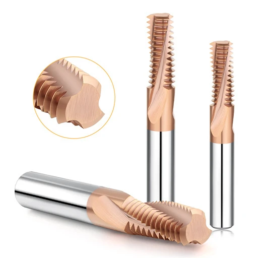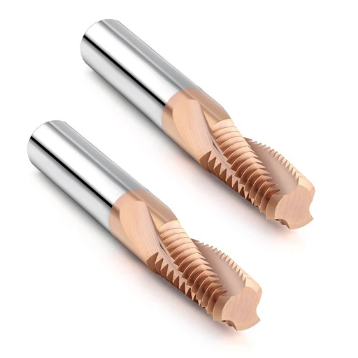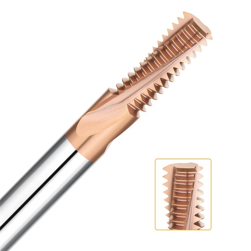

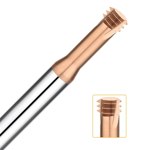
A precision injection mold shop in Ohio called us with an urgent problem: machining M6×1.0 threads into AISI H13 inserts hardened to HRC 58–60. Mid-cycle, the spindle began emitting a piercing screech. When the operators stopped the machine, they found wavy micro-spalling across the thread flanks. Worse, the No-Go gauge slipped right in, and tool life dropped by half. This was a classic, costly case of thread mill chatter.
We see this scenario repeatedly while supporting job shops, aerospace machinists, and mold makers across North America and Europe. In pre-hardened steels like P20, slight resonance only causes poor surface finish. In fully hardened tool steels, however, a dynamic deflection of just a few microns will instantly chip a carbide cutting edge.
Troubleshooting thread mill vibration in hardened steel requires far more than just swapping in a coated tool. Real-world failures stem from interconnected issues:
-
Runout & Balance: Small runout at the tool tip multiplies under severe cutting resistance, overloading individual teeth.
-
Overhang & Rigidity: Long reach thread mills flex under radial cutting forces, causing dynamic rigidity to collapse in deep cavities.
-
Micro-Tool Core Strength: Small diameter thread mills lack the core mass needed to resist cutting harmonics.
-
Toolpath Strategy: Standard toolpaths lack the radial multi-pass step-downs and tangential arc lead-ins required for high-hardness materials.
Generic textbook cutting data offers little help here. You need a systematic, physical audit of the cutting edge geometry, holder rigidity, spindle harmonics, and CAM lead-in moves.
If your VMC is screaming and you are risking a scrapped workpiece, take a step back before touching the speed or feed overrides. Ask yourself: is your tool truly operating within its dynamic balance and rigidity limits?
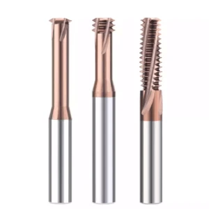
The Nature of Chatter in Thread Milling Hardened Steel: Real-World Failure Characteristics on the Shop Floor
By the time you hear the cut change pitch outside the enclosure, severe vibration has already compromised the tool-workpiece interface. Many machinists simply blame “machine shake,” but vague diagnoses ruin parts. When evaluating thread milling vibration above HRC 55, do not touch the feed override dial first. Stop the spindle immediately and inspect the cutting edges under a 50x optical loupe.
Cutting marks on hardened steel never lie. The material offers virtually zero plastic deformation to cushion dynamic loads, freezing every microscopic wave onto the cut surface. Thread flanks show distinct ripple patterns, and thread plug gauges bind halfway through the hole. Identifying this physical failure pattern early is the only way to save high-value tooling and components.
Thread Milling in Hardened Mold Steel: Micro-Chipping, Thread Profile Distortion, and Abnormal High-Pitched Screeching
At an automotive stamping plant in Germany, operators were milling M8 threads into H13 inserts. After just five holes, brand-new cutters produced a high-pitched screech like fingernails on a chalkboard. Under the microscope, the tool showed stepped micro-chipping along the secondary relief rather than normal abrasive flank wear. This noise signals rapid tool bouncing against hard carbide inclusions, not simple cutting overload.
The direct result of this bouncing is severe thread profile distortion. When using a specialized thread mill for hardened mold steel, dynamic instability shifts the tool center off its programmed orbital path. The standard 60-degree flank angle can distort to 58 or 63 degrees, blowing out pitch diameter tolerances. If the go gauge passes but the no-go gauge enters too, verify tool bouncing before blaming the thread grinder.
Distinguishing the Source of Vibration: Static Deflection vs High-Frequency Thread Mill Chatter
To fix stability problems, you must diagnose the root physical mechanism: static bending deflection or self-excited resonance. We frequently see process technicians confuse long-overhang bending with harmonic chatter. They drop spindle speeds drastically, which spikes chip load per tooth and snaps the tool off at the bottom of the hole. These two failures require completely opposite corrective actions.
You can diagnose the source with a simple shop-floor rule of thumb. If the hole has a steady taper without ripple marks and sounds dull and heavy, the tool shank is experiencing static bending deflection under heavy radial load. If you hear a sharp squeal, see fine striations on the thread flanks, and find chipped edges, you face high-frequency thread mill chatter. Solving it requires breaking dynamic phase overlap, not just stiffening the setup.
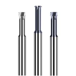
Clamping Systems and Runout Troubleshooting: The Often-Overlooked Issue of Thread Mill Runout
In our field troubleshooting, at least 40% of chatter issues trace back to the toolholder assembly rather than the tool or feed parameters. Many shops apply aluminum-level tolerances to hardened components, clamping tools into worn ER collets. A 0.01 mm runout might only cause mild uneven wear in soft steel. In hardened materials, severe cutting resistance amplifies that error into periodic radial shock loads.
Putting a test indicator on the spindle nose quickly exposes root causes that baffle process engineers. Dried coolant on toolholder tapers, weak drawbar retention force, or fretting wear inside collet bores all trigger severe thread mill runout. If your tool consistently chips on the exact same one or two teeth, check the holder first. Clean the spindle taper and collet bore thoroughly, then re-indicate total indicator reading (TIR) at the tool tip.
The Bottom Line for Runout Control: Why Runout Must Stay Below 3μm When Thread Milling HRC60 Steel
We once helped a Swiss medical device shop overcome a severe bottleneck in cold-work tool steel. Workpiece hardness hovered near HRC 60, and tool life stalled at just two to three holes per cutter. On-machine inspection showed 8 microns of radial runout at the tool tip. In general machining, 8 microns sounds acceptable. But during thread milling HRC60 steel, nominal chip load per tooth (Fz) runs between 0.008 mm and 0.015 mm.
At 8 microns of runout, one or two teeth carry 100% of the cutting load while the rest rub dry. This severe load imbalance spikes instantaneous stress well past the carbide grain boundary strength. That is why we enforce a strict 3-micron runout ceiling for our North American and European accounts. Keeping runout below 3μm balances microscopic chip thickness across all cutting flutes and eliminates tooth-to-tooth radial shock.
Shrink-Fit Toolholders vs Precision Hydraulic Chucks: Rigidity Differences in Eliminating Thread Milling Vibration
Shop supervisors often ask whether shrink-fit holders or hydraulic chucks handle vibration better. Both hold tight runout, but they behave differently under load. Shrink-fit holders deliver maximum static radial rigidity and a short, rigid nose profile. They excel at resisting bending under heavy side loads. However, their material damping is near zero, meaning high-frequency cutting harmonics reflect straight back into the carbide edge.
Precision hydraulic chucks feature an internal fluid membrane that dampens high-frequency resonance. They excel at smoothing out the harmonics that cause thread milling vibration. Their multi-piece construction does sacrifice a small amount of raw bending stiffness compared to heavy shrink-fit holders. For tight cavities requiring maximum bending resistance, choose slim-nose shrink-fit tooling. For standard depths plagued by high-pitched acoustic chatter, hydraulic chucks deliver immediate vibration relief.
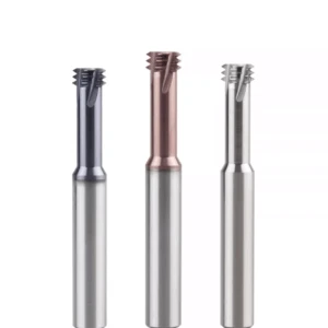
Tool Overhang and System Rigidity: Controlling Long Reach Thread Mill Vibration
Machinists often choke up tools too far out of holders to clear fixtures or deep walls. In hardened steel, deflection does not scale linearly with overhang—it collapses at a cubic rate. Heavy cutting resistance quickly turns an extended shank into a mechanical tuning fork. This imbalance between thread mill tool overhang & rigidity deprives the cutting edge of solid support the instant it touches the bore wall.
Eliminating this instability requires strict discipline during setup planning: choke up on the tool shank whenever clearance allows. We always review holder clearance profiles to ensure shortest possible projection. If clearance allows, choose a tapered, reinforced neck to maximize cross-sectional stiffness. If long reach is unavoidable, reduce your radial depth of cut per pass to keep cutting deflection inside the elastic limit.
The Overhang Ratio (L/D) Red Line: Rigidity Compensation for Long Reach Thread Mills
An overhang ratio of 4:1 or 5:1 may work in mild steel, but 3:1 is the hard limit for hardened mold steels over HRC 55. A North American mold shop once snapped three consecutive tools trying to thread water lines at 3.5D depth. The cut produced a heavy drone followed by sudden tool fracture. In high-hardness steel, running a standard multi-tooth cutter across a full helical pass creates excessive tool flex that speed overrides cannot fix.
To solve deep-reach chatter, we swap full-profile cutters for single-tooth or three-tooth staggered geometries paired with stepped neck profiles to restore thread mill rigidity. Slashing axial cutting contact by over 70% drops radial deflection forces exponentially. This brings bending strain on the long reach thread mill back into a stable range. Deep holes are manageable if you reduce total tooth contact to preserve tool tip stiffness.
Small Diameter Thread Mill Design: Shank Reinforcement and Substrate Selection for Vibration Resistance
When threading drops below M3 down to micro sizes like M1.6, the physics become unforgiving. Micro-tool cores are fragile, and standard straight-shank blanks twist and vibrate under high cutting resistance. While tooling medical implant components, we standardize on a small diameter thread mill geometry with reinforced, stepped shanks. A smooth blending radius transitions the cutting neck into a larger shank, keeping the thin neck strictly at the thread depth limit.
Substrate chemistry matters just as much as geometry. Machinists often assume harder carbide grades perform better in hardened steel. Ultra-fine micro-grain carbide provides high hardness, but it sacrifices transverse rupture strength (TRS). We specify specialized sub-micron substrates with balanced cobalt content for improved bending resistance and impact toughness. Paired with heat-resistant nano-coatings, this resilient core absorbs cutting micro-shocks without edge chipping.
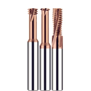
Optimizing Toolpaths and Cutting Parameters: Field-Proven Solutions for Thread Milling Chatter
When chatter ripples appear, many machinists reflexively drop feed override to 50% or lower. In hardened tool steels, this rarely works. It often pushes the cutter into a dry-rubbing zone, causing friction and thermal breakdown. We teach our clients across North America and Europe a key rule: resolve dynamic instability by reconfiguring entry moves and redistributing cutting loads, not by making passive parameter cuts.
Proven thread milling chatter solutions keep every tooth inside the machine’s dynamic stability pocket. Minor CAM oversights quickly trigger high-impact chatter when cutting hardened stock. This includes bad helical entry locations and missed circular feed compensation. Aligning radial step-over, lead-in arc radius, and spindle harmonics solves loud squealing and tool chipping on the spot without replacing holders or tooling.
Radial Layering Strategy: Single Pass vs Multi Pass Load Distribution
Never use a single-pass cycle on materials harder than HRC 55. While troubleshooting an automotive fixture plant in the UK, we watched an operator attempt a 1.25 mm thread depth in one pass. The tool groaned upon contact, deflecting 0.05 mm and ruining the thread minor diameter. Extreme hardness creates massive lateral thrust across full tooth engagement, pushing the tool off-center and making single-pass precision impossible.
We always mandate a multi-pass radial infeed strategy. For HRC 55+ steels, split stock removal into two or three radial passes using a descending ratio like 60%, 30%, and 10%. Finish with a very shallow spring pass to clean up residual deflection. This protects delicate carbide teeth from shock loads during roughing while allowing the shank to spring back on finish passes for crisp, gauge-perfect threads.
Controlling Entry and Exit Arcs: Thread Mill Chatter Prevention
Beyond step-overs, entry and exit toolpaths determine tool life. We often find client programs driving tools straight into hole walls on linear paths. While fine in mild steel, this hits carbide cutting edges like a hammer blow in hardened stock. The sudden spike from zero to peak cutting force causes shock-induced entry marks, ruining part quality from the start.
For effective thread mill chatter prevention, always program smooth 90-degree or 180-degree tangential arc lead-ins and lead-outs. Blend the cutter smoothly from the bore center into the hole wall along a clean circular sweep while ramping Z-axis pitch. Exit with a matching tangential sweep. This gradual transition eliminates sudden radial shock spikes and leaves zero dwell marks behind.
Real Cutting Speed (Vc) and Feed per Tooth (Fz): Field-Proven Windows
A common pitfall is overlooking the difference between programmed tool-center feed and actual tool-edge feed. In small-bore internal helical milling, tight curvature means edge feed can be triple the programmed center value. Setting nominal feed too low causes teeth to burnish rather than cut. This generates extreme frictional heat, softening and dulling carbide edges rapidly.
For tool steels between HRC 58 and 62, keep cutting speed (Vc) inside a tight window of 40 to 70 m/min. Avoid chasing excessive surface speeds. Control chip load (Fz) strictly between 0.008 and 0.02 mm/tooth depending on tool projection. Excessive chip loads snap thin shanks, while light chip loads cause edge rubbing and high-frequency resonance. Dialing in this sweet spot turns piercing spindle screams into a smooth, steady hum.
Fine-Tuning Tool Geometry: Solving Thread Mill Vibration in Hardened Steel
Adjusting runout, tool overhang, and radial passes resolves most shop-floor issues. Yet even with runout held below 3 microns in short shrink-fit holders, stubborn harmonics can still cause high-pitched whining. When external process tweaks fail, look closely at tool macro- and micro-geometry.
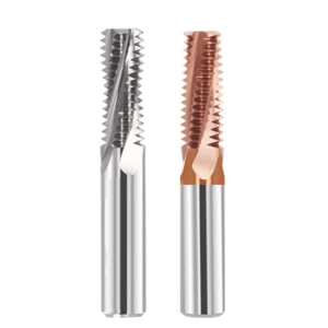
Standard catalog thread mills are often just general-purpose cutters with dark high-hardness coatings. Their deep chip flutes and aggressive positive rakes compromise core strength under heavy cutting forces. To eliminate thread mill vibration hardened steel, you must modify the tool grinding geometry. Disrupting force harmonics and reinforcing edge cross-sections provides internal damping right at the cutting interface.
Unequal Flute Spacing and High Helix Angles: Breaking Harmonic Resonance
Standard thread mills with equal flute spacing hit hardened workpieces at perfectly matched time intervals. At HRC 55+, these force pulses rapidly superimpose, coupling with the spindle’s natural frequency and triggering regenerative chatter. We resolved this for European stamping die customers by introducing variable flute spacing paired with high-helix flutes.
Unequal flute indexing alters tooth contact phase angles so wave crests from one tooth cannot amplify the next. This breaks harmonic resonance mechanically. High helix angles create a smooth slicing action across the cut, reducing intermittent shock and steering radial forces upward into the rigid spindle axis. If you struggle with deep blind-hole squeal, inspect your tool flutes and switch to variable-helix geometry.
Edge Honing and Micro-Radius Prep: Balancing Strength and Cutting Drag
Machinists often assume sharper cutting edges slice hardened steel better. In reality, razor-sharp edges chip immediately against hardened carbide inclusions. Once microscopic chipping starts, the edge hammers the wall, accelerating chatter and tool failure. Conversely, heavy rounding raises radial tool drag, pushing slender tools off-center.
When grinding tools for HRC 58–62 tool steels, we apply a controlled edge hone between 5 and 12 microns combined with a narrow negative T-land. This micro-radius supports brittle carbide grain boundaries under heavy shock loads without causing tool rub. The reinforced edge prevents premature micro-spalling while keeping cutting resistance low.
If you are fighting chatter and micro-chipping in deep hardened holes, start by auditing your runout, overhang ratios, and radial step-downs. If chatter persists after checking these variables, you can share your part prints, heat-treat specs, and machine setup with us. We can review your application together and tailor an anti-vibration tool geometry designed for your exact job.