In the field of precision machining, micro carbide milling cutters are widely used for machining complex components such as electronic parts, medical devices, and precision molds. However, due to their small diameters and inherently low structural strength, issues like tool breakage, chipping, and poor surface quality are common in CNC operations. Especially under high-speed spindle and micro-feed conditions, improper tool handling can lead to early-stage breakage, significantly impacting machining efficiency and part yield.
This article combines hands-on CNC engineering experience to analyze the root causes of breakage in micro carbide milling cutters from the perspectives of tool design, clamping systems, machining parameters, and machine rigidity. It also provides actionable solutions to help engineers improve tool stability and extend cutter life. Additionally, we offer tips on how to choose reliable micro carbide milling cutter manufacturers to support high-precision micro-machining applications.

Structural Characteristics and Breakage Risks of Micro Carbide Milling Cutters
What Is a Micro Carbide Milling Cutter?
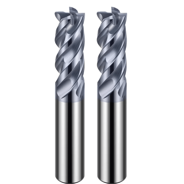
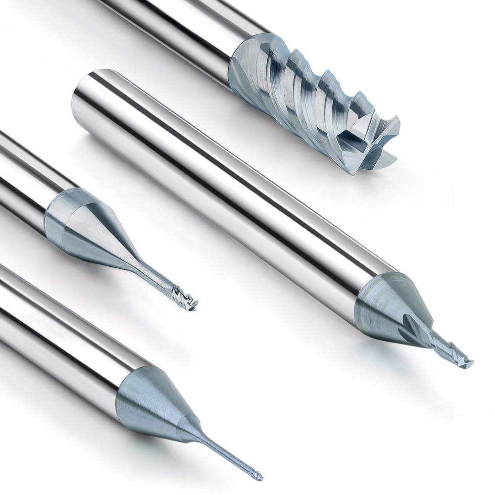
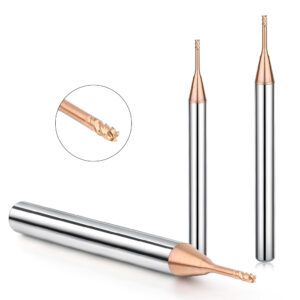
A micro carbide milling cutter—also referred to as a micro tungsten steel end mill—is a milling tool with a cutting diameter typically less than 3 mm, made from ultra-fine grain carbide. These tools are essential for high-precision CNC micro-milling tasks in industries like 3C electronics, IC packaging, medical mold cavities, and micro-connectors. Common diameters include Φ0.1 mm, Φ0.2 mm, and Φ0.5 mm, with some applications requiring ultra-micro end mills down to Φ0.03 mm.
Why Are Micro Milling Cutters More Prone to Breakage?
Micro milling cutters are significantly more fragile than standard-sized tools due to the following reasons:
-
Poor Bending Rigidity Due to Small Diameter
Their extremely small diameters make them vulnerable to offset loads and uneven cutting forces. Tools under Φ0.2 mm are especially sensitive to even minor lateral stress. -
Amplified Vibration at High Spindle Speeds
Micro tools typically operate at spindle speeds above 20,000 RPM. Any spindle runout or micro-jump gets amplified, creating impact forces that often result in sudden tool breakage. -
Brittle Tool Materials with Low Tolerance
Micro end mills are usually made from hard but brittle materials like tungsten carbide or nano-coated carbides (e.g., CEMEGA, AFH20U). Although highly wear-resistant, these materials are sensitive to chipping under improper loading or interrupted cutting.
For these reasons, when using micro carbide end mills, it’s critical to control every aspect of the machining process—environment, parameters, equipment, and handling—to maximize tool performance and lifespan.

Common Causes of Micro Milling Cutter Breakage in CNC Machining
Tool breakage during high-precision CNC micromachining is often not just a tooling issue but a systemic one. Factors like spindle condition, tool holder accuracy, parameter tuning, and vibration control all contribute to mini end mill failures.
Spindle Runout and Tool Holder Clamping Issues
Spindle runout can severely reduce the life of micro end mills. For example, a 3 μm runout translates to a 15% radial error on a Φ0.2 mm cutter, resulting in uneven cutting force and early tool failure.
Recommendations:
-
Use a dial indicator and precision gauge pin to check Total Indicated Runout (TIR).
-
Ensure spindle runout stays below 3 μm; high-end electric or air bearing spindles are ideal.
-
Use high-precision collets (e.g., ER11/ER16 H-class) or shrink-fit holders to maintain concentricity.
-
Avoid worn or low-quality tool holders that compromise clamping accuracy.
The synergy between spindle and tool holder precision directly affects micro cutter stability and longevity.
Improper Cutting Parameter Settings
Incorrect feed rates, cutting depths, or spindle speeds are another major cause of tool failure. Contrary to popular belief, smaller cutters cannot simply “cut more” because their structural limits are easily exceeded.
Common mistakes:
-
Excessive feed leads to overload.
-
Deep cuts overstrain the fragile tool body.
-
Inadequate spindle speed causes rubbing instead of cutting, resulting in fractures.
Recommended Parameter Ranges:
| Material Type | Tool Diameter | Cutting Depth (ap) | Cutting Width (ae) | Spindle Speed | Feed Rate |
|---|---|---|---|---|---|
| Copper / Aluminum Alloys | Φ0.2 mm | 0.02 mm | 0.05 mm | 30,000–60,000 RPM | 200–400 mm/min |
| Tool Steel | Φ0.2 mm | 0.01 mm | 0.03 mm | 40,000–80,000 RPM | 150–300 mm/min |
| Graphite / Ceramics | Φ0.3 mm | 0.015 mm | 0.04 mm | Above 50,000 RPM | 100–250 mm/min |
It is recommended to use conservative parameters for the first processing and fine-tune them according to actual working conditions. Especially in batch applications, it is recommended to preset small end mill parameter templates through CAM software or experience database to significantly reduce the risk of tool breakage.
Poor Workpiece Clamping and Vibration Control
Micro tools rely heavily on system rigidity. Weak or unstable clamping setups introduce micro-vibrations that are enough to cause tool failure.
Why micro tools are more vibration-sensitive:
-
Low mass and inertia make them highly reactive to vibrations.
-
Tip loads are concentrated, so any asymmetry results in uneven stress.
-
High-speed rotation amplifies vibration magnitude and frequency.
Solutions:
-
Use vacuum tables with mechanical limits or rigid custom fixtures.
-
Install machines on granite bases or vibration-damping structures.
-
Keep tool overhangs minimal (L/D < 3 recommended).
A rigid system setup is essential for optimizing tool life and avoiding catastrophic tool failure.

How to Use Micro End Mills Properly to Extend Tool Life
Due to their fragile geometry and low bending stiffness, micro carbide end mills require careful handling and optimized process planning. The following best practices can significantly reduce wear and breakage:
Adopt a Layered Machining Strategy
Instead of deep one-pass cuts, use multiple shallow passes. This approach minimizes the tool load and improves stability.
Best practices:
-
For tools under Φ0.2 mm, keep cutting depth below 10% of the tool diameter.
-
Mill layer by layer to distribute forces evenly and avoid excessive initial loading.
Layered strategies are standard in micro mold manufacturing, microfluidic channel machining, and high-precision cavity creation.
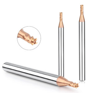
Choose the Right Tool Diameter and Flute Count
Micro cutters should not blindly follow the design of full-sized tools. In most cases, fewer flutes offer better performance for ultra-small-diameter end mills.
Why fewer flutes work better:
-
Wider chip flutes enhance chip evacuation.
-
Fewer flutes reduce friction and minimize “rubbing” instead of cutting.
-
For sticky materials like aluminum and copper, low-flute tools reduce the chance of built-up edge (BUE) and chipping.
For Φ0.1–0.3 mm cutters, 1-flute or 2-flute (with wide spacing) tools are ideal, especially under high-speed spindles.
Use the Right Cooling and Lubrication
In micro machining, the accumulation of cutting heat is a major factor contributing to reduced tool life. A proper cooling and lubrication strategy not only helps dissipate heat effectively but also assists with chip evacuation, reduces tool wear, and prevents thermal cracks and surface burning.
Comparison of Common Cooling Methods
| Cooling Method | Typical Applications | Advantages | Disadvantages |
|---|---|---|---|
| Air Cooling | High-speed spindles / dry cutting | Chip removal, clean and contamination-free | Limited heat dissipation |
| Mist Cooling | Medium-speed machining | Cooling + lubrication combined | Requires oil mist control system |
| Minimum Quantity Lubrication (MQL) | Machining steel and hard materials | Excellent lubrication, energy-efficient, eco-friendly | Requires dedicated MQL system |
Note: Some high-performance carbide micro end mills feature nano-coating designs that offer excellent heat resistance, making them suitable for dry cutting or low-lubrication conditions. However, for extended machining times or deep cavity structures, it is recommended to use MQL or mist cooling to enhance stability.
Therefore, selecting the appropriate cooling method for micro milling projects should consider factors such as tool material, workpiece material, machining strategy, and machine capabilities. Insufficient cooling can lead to premature tool failure and reduced process reliability.
How to Choose a High-Quality Micro Carbide Milling Cutter
The quality of micro carbide milling cutters directly affects machining efficiency, accuracy, and tool life. High-precision micro cutters demand manufacturing accuracy, material uniformity, and stringent factory inspection. Choosing a reliable manufacturer is crucial.
Choose a Trusted Micro Carbide Milling Cutter Factory
Reliable micro milling cutter suppliers generally feature:
Advanced and Complete Production Equipment
-
Five-axis CNC grinders from Switzerland or Germany (e.g., ROLLMATIC, WALTER) for precise tool contour and edge quality.
-
High-precision inspection tools (Zoller tool presetters, projectors, laser gauges) for thorough quality control.
-
Temperature- and humidity-controlled production environments to ensure batch consistency.
Factory Accuracy and Dimensional Consistency
-
Outer diameter tolerance within ±0.002 mm.
-
Consistent blade length, shank diameter, and flute count across batches.
-
SPC (Statistical Process Control) charts to monitor manufacturing variations.
Manufacturers with independent R&D and custom service capabilities offer better process optimization, delivery, and technical support.
Comparing Micro End Mill Brands: Tool Life and Breakage Control
In real-world applications, the performance gap between different micro end mills is most evident in two key areas: tool life and breakage control. Variations in material selection, coating technology, and cutting edge design across brands largely determine a tool’s stability in actual machining scenarios.
H4:Domestic vs. Imported Brands: A Brief Comparison
| Criteria | Domestic Brands (e.g., from Guangdong, Jiangsu) | Imported Brands (e.g., Germany, Switzerland, Japan) |
|---|---|---|
| Material Stability | Typically use YG-grade tungsten steel with some variation | Use ultra-fine grain carbide with consistent quality |
| Dimensional Consistency | High-end brands can maintain ±0.003 mm | Typically controlled within ±0.001 mm |
| Coating Technology | Mainly basic CVD or AlTiN coatings | Advanced coatings such as DLC, nACo, nano-TiSiN |
| Tool Life | Moderate, requires careful parameter control | Long tool life with higher tolerance for variation |
| Breakage Risk | Low tolerance, recommend small step-over strategies | High tolerance, suitable for high-speed machining |
Application Scenarios and Selection Tips
-
For stable batch production, imported micro CNC end mills are recommended to ensure consistent machining quality and reduce downtime.
-
For prototype or small-batch runs with tightly controlled parameters, some high-end domestic micro tools can offer excellent cost-performance ratios.
-
For complex geometries or difficult materials (e.g., titanium alloys, ceramic composites), prioritize imported tools with patented edge designs and advanced high-hardness coatings.
Additionally, when selecting a supplier, it’s important to check whether they offer sample testing or small-batch trial services. This can significantly reduce trial-and-error costs and help validate tool performance more efficiently.

Stable Processing of Micro Parts: Choosing the Right Tool and Process Is Key
In CNC machining of micro parts, tool breakage of micro carbide milling cutters remains a core challenge to process stability. From the analysis above, it is clear that the successful application of tungsten micro milling cutters depends not only on the tool’s performance but also on the coordinated optimization of three key elements: tool quality + process parameters + machining system.
First, from a tool structure standpoint, micro end mills are extremely sensitive to vibration and spindle runout at high spindle speeds due to their very small diameter, low rigidity, and limited chip evacuation space. Therefore, strict control of spindle TIR is essential—ideally kept at or below 3 μm. Selecting a high-precision tool holder system and using rigid workpiece fixtures help reduce the cumulative effect of cutting vibrations.
Second, reasonable cutting parameter settings are critical. Micro milling cutters are not suitable for high feed rates or heavy loads. Instead, multiple shallow passes, multi-axis interpolation, and cutting parameters optimized according to the material properties should be used. Additionally, appropriate cooling strategies—such as MQL or dry cutting—should be combined to enhance chip evacuation and thermal management. This is especially important when machining hard and brittle materials like tungsten micro cutters, where avoiding sudden impacts and thermal cracks is crucial.
Furthermore, extending tool life relies on scientific tool selection and process path planning. For example, using 1-flute or 2-flute micro end mills can reduce cutting resistance and improve cooling efficiency. Layered machining strategies effectively reduce the cutting load per pass, serving as a practical way to prevent tool breakage.
Finally, choosing a reputable micro carbide milling cutter manufacturer is the first step toward successful micro machining. Manufacturers equipped with high-precision production equipment, comprehensive quality inspection processes, and mature brand experience offer more stable, consistent products and reliable technical support—an indispensable guarantee for achieving high-yield micro machining.