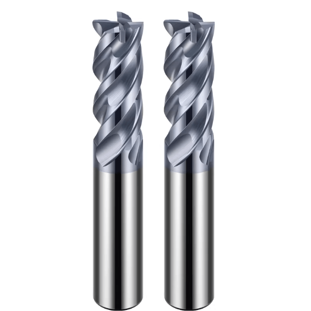
Selecting the right end mill is a critical aspect of CNC machining that directly influences efficiency, quality, and cost. An end mill, or end mill bit, comes in various materials, coatings, and geometries, each suited to specific machining tasks and workpiece materials. For instance, high-speed steel (HSS) and carbide are popular choices, with carbide offering superior hardness and heat resistance, making it ideal for high-speed operations. The selection process also involves considering the diameter and length of the end mill to ensure sufficient rigidity and to minimize vibrations during end milling. Additionally, the number of flutes on an end mill affects chip removal and cutting stability, with more flutes providing smoother finishes but potentially reducing chip clearance.https://samhotool.com
Furthermore, end milling success is greatly influenced by factors such as cutting speeds, feed rates, and cooling methods. Properly selecting and managing these parameters can extend tool life and improve surface finish. The choice of coatings like TiN or TiAlN can further enhance performance by reducing friction and wear. Effective chip evacuation, crucial in preventing tool damage and workpiece surface defects, is facilitated by selecting end mills with appropriate helix angles and flute designs. Beyond the tools themselves, the rigidity and power of the CNC machine, as well as the chosen tool-holding method, play significant roles in achieving optimal end milling results. Advanced tool management systems and continuous learning are essential for staying updated with the latest advancements in end mill technology, ensuring high-quality and cost-effective machining processes.
Analysis of End Mill Materials
End mill materials play a crucial role in determining the performance and suitability of a tool for specific machining tasks. The choice of material impacts the tool’s durability, cutting speed, and the quality of the finished product. Here, we delve into the common materials used for end mills and their specific applications.
High-Speed Steel (HSS)
High-Speed Steel (HSS) is a widely used material for end mills due to its versatility and cost-effectiveness. HSS end mills are known for their toughness and ability to withstand shock and vibration, making them ideal for machining softer materials such as aluminum, brass, and mild steel. Despite being less hard and heat-resistant than carbide, HSS tools can perform well at lower speeds, offering a good balance between performance and cost for general-purpose milling.
Carbide
Carbide end mills are preferred for high-speed and high-hardness applications. Composed of tungsten carbide particles bonded with cobalt, these tools offer exceptional hardness and heat resistance, enabling them to maintain a sharp cutting edge even at high temperatures. Carbide end mills are ideal for machining hard materials like stainless steel, titanium, and superalloys. Their ability to perform at higher speeds and feeds significantly boosts productivity, although they are more brittle and prone to chipping compared to HSS.
Ceramic
Ceramic end mills are used for high-temperature and high-speed applications. They are particularly effective for machining hard, abrasive materials such as nickel-based superalloys and hardened steels. Ceramic tools can operate at extremely high speeds and temperatures without losing their hardness, reducing the need for coolant and enhancing machining efficiency. However, their brittleness requires careful handling and specific cutting conditions to prevent breakage.
Diamond
Diamond-coated and polycrystalline diamond (PCD) end mills are among the hardest and most wear-resistant tools available. They are particularly useful for machining non-ferrous materials such as aluminum, copper, and composites. The exceptional hardness of diamond ensures prolonged tool life and excellent surface finishes. Diamond tools are indispensable in industries where precision and surface quality are paramount, despite their high cost and specialized application requirements.
In summary, the choice of end mill material is fundamental to achieving optimal machining performance. High-Speed Steel offers a cost-effective solution for general-purpose milling, while carbide end mills excel in high-speed, high-hardness applications. Ceramic tools provide superior performance in high-temperature environments, and diamond-coated end mills are unmatched for non-ferrous materials requiring high precision. Understanding the specific properties and applications of each material allows for informed decision-making, ensuring efficient and high-quality milling operations.
Analysis of Tool Geometry
The geometry of an end mill, encompassing features such as rake angle, relief angle, and helix angle, plays a crucial role in its cutting performance and suitability for different materials and machining conditions. Each geometric feature contributes to the tool’s efficiency, cutting force, and the quality of the machined surface. Here, we explore the significance of these geometrical parameters in depth.
Rake Angle
The rake angle, or the angle between the cutting edge and the workpiece, significantly impacts the cutting efficiency and chip flow. Positive rake angles reduce cutting forces and facilitate smoother chip evacuation, making them ideal for machining softer materials like aluminum and plastics. Negative rake angles, on the other hand, provide greater edge strength and are better suited for harder materials such as stainless steel and cast iron, where tool durability is critical.
Relief Angle
The relief angle, also known as the clearance angle, is the angle behind the cutting edge that prevents the tool from rubbing against the workpiece. Proper relief angle ensures minimal contact with the workpiece, reducing friction and heat generation. A larger relief angle reduces the risk of tool wear and extends tool life but may compromise tool strength. Conversely, a smaller relief angle enhances tool rigidity, beneficial for machining hard materials, albeit with increased risk of wear and potential for higher cutting temperatures.
Helix Angle
The helix angle, or the angle of the tool’s spiral flutes, affects the cutting action and chip removal process. A higher helix angle (closer to 45 degrees) provides a smoother cutting action and better chip evacuation, ideal for high-speed machining and finishing operations. This angle helps in reducing vibration and ensuring a superior surface finish. Lower helix angles (around 30 degrees) are preferred for tougher materials and applications requiring higher cutting forces, as they provide greater rigidity and support to the cutting edge.
The geometry of an end mill is pivotal to its performance in various machining applications. The rake angle determines the cutting force and chip flow, with positive angles favoring softer materials and negative angles suitable for harder ones. The relief angle impacts tool wear and heat generation, balancing between tool life and strength. Lastly, the helix angle influences the cutting action and chip removal, with higher angles enhancing smoothness and lower angles providing rigidity. Understanding these geometric parameters allows for the precise selection and optimization of end mills, ensuring efficient and high-quality machining across diverse materials and conditions.

Analysis of Coating Types
Coatings on end mills play a vital role in enhancing tool life and performance by reducing friction, increasing hardness, and providing thermal stability. The choice of coating depends on the specific machining conditions and materials being processed. Here, we delve into the characteristics and applications of common coatings such as TiN, TiCN, TiAlN, and DLC.
Titanium Nitride (TiN)
Titanium Nitride (TiN) is one of the most widely used coatings for end mills due to its excellent hardness and wear resistance. TiN-coated tools are characterized by their golden color and provide a significant improvement in tool life compared to uncoated tools. This coating reduces friction and can withstand moderate temperatures, making it suitable for a variety of materials, including steels, cast iron, and aluminum. TiN is ideal for general-purpose machining where increased tool life and reduced wear are desired.
Titanium Carbo-Nitride (TiCN)
Titanium Carbo-Nitride (TiCN) offers enhanced performance over TiN by incorporating carbon into the coating, resulting in increased hardness and wear resistance. TiCN has a bluish-grey color and provides better performance in high-speed and high-feed machining conditions. It is particularly effective for machining harder materials such as stainless steel and high-carbon steels. The increased hardness and lower friction coefficient of TiCN make it suitable for more demanding applications, extending tool life and improving productivity.
Titanium Aluminum Nitride (TiAlN)
Titanium Aluminum Nitride (TiAlN) is known for its high thermal stability and oxidation resistance, making it ideal for high-temperature applications. TiAlN-coated tools are typically dark violet or black and are used in machining tough materials such as titanium alloys, Inconel, and other heat-resistant superalloys. The aluminum content in the coating forms a protective oxide layer at elevated temperatures, which enhances tool performance and longevity. TiAlN is preferred for dry machining and applications where high cutting speeds and feeds are required.
Diamond-Like Carbon (DLC)
Diamond-Like Carbon (DLC) coatings offer a unique combination of extreme hardness, low friction, and excellent wear resistance. DLC coatings are typically black and provide superior performance in non-ferrous materials such as aluminum, copper, and composites. The low friction coefficient of DLC reduces adhesion and buildup on the tool, ensuring smooth cutting action and high-quality surface finishes. DLC is particularly beneficial in high-precision applications where surface finish and tool longevity are critical.
In short, selecting the appropriate coating for an end mill is essential to optimize machining performance and extend tool life. TiN coatings provide a good balance for general-purpose use, enhancing tool wear resistance across various materials. TiCN coatings offer improved hardness and performance for tougher materials and high-speed conditions. TiAlN coatings excel in high-temperature applications, providing thermal stability and oxidation resistance for machining hard alloys. DLC coatings are unmatched for non-ferrous materials, offering exceptional hardness and low friction for high-precision tasks. Understanding the specific benefits and applications of each coating type allows for informed decisions, ensuring efficient and effective machining operations.
Analysis of Tool Flute Count
The number of flutes on an end mill is a critical factor influencing cutting performance, chip evacuation, and the smoothness of the cut. Different applications and materials require specific flute configurations to optimize efficiency and surface finish. Here, we examine the impact of flute count on tool performance and suitability for various machining tasks.
Fewer Flutes: High Efficiency in Roughing
End mills with fewer flutes, typically two or three, are designed for roughing operations where material removal rate is prioritized. The larger space between flutes allows for efficient chip evacuation, reducing the risk of clogging and enabling higher feed rates. This configuration is ideal for softer materials such as aluminum and plastic, where quick material removal is necessary. The increased chip clearance also helps in preventing overheating and maintaining a cooler cutting environment, which prolongs tool life.
More Flutes: Precision in Finishing
End mills with a higher number of flutes, usually four or more, are used for finishing operations where surface quality and dimensional accuracy are critical. The increased number of cutting edges results in smoother cuts and finer finishes, as more edges are engaged with the workpiece simultaneously. This setup is suitable for harder materials and applications requiring tight tolerances, such as mold making and precision component manufacturing. However, the reduced chip space necessitates careful management of cutting parameters to avoid chip buildup and ensure effective cooling.
Balancing Flute Count with Material and Operation
Selecting the appropriate flute count involves balancing the material being machined and the specific operation. For instance, a three-flute end mill is often used for slotting and pocketing in softer materials due to its balanced chip evacuation and cutting efficiency. On the other hand, a five-flute end mill may be preferred for finishing operations in harder materials, providing a smoother surface and reduced vibration. The optimal flute count ensures that the tool performs efficiently without compromising on the quality of the machined surface or the tool’s lifespan.
The number of flutes on an end mill significantly influences its cutting performance, chip evacuation, and suitability for various machining tasks. Fewer flutes enhance material removal rates and chip clearance, making them ideal for roughing operations in softer materials. Conversely, more flutes provide smoother finishes and higher precision, suitable for finishing tasks and harder materials. Understanding the relationship between flute count, material properties, and machining requirements allows for informed tool selection, ensuring efficient and high-quality machining processes tailored to specific needs.
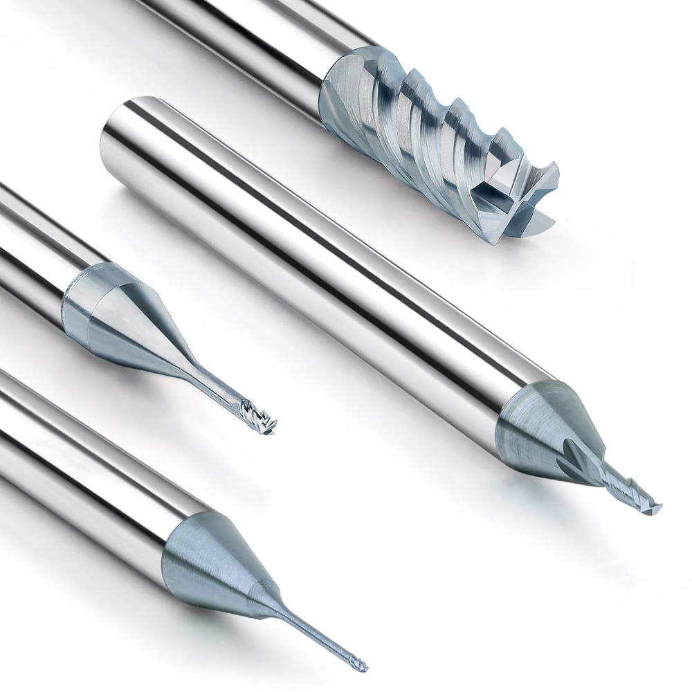
Analysis of Tool Diameter
The diameter of an end mill is a crucial parameter that affects its rigidity, cutting efficiency, and suitability for specific applications. Selecting the appropriate tool diameter ensures optimal performance and longevity in various machining operations. Here, we explore the implications of tool diameter on machining outcomes.
Rigidity and Stability
Larger diameter end mills offer increased rigidity, which enhances stability during cutting operations. This rigidity reduces deflection and vibration, leading to more accurate cuts and improved surface finishes. In heavy milling applications, such as roughing large parts or cutting hard materials, a larger diameter tool is preferred because it can withstand higher cutting forces without compromising the tool’s integrity. This stability also allows for higher feed rates and deeper cuts, boosting overall machining efficiency.
Cutting Efficiency and Material Removal
End mills with larger diameters can remove more material per pass, improving productivity in bulk material removal processes. They are particularly effective in roughing operations where large volumes of material need to be quickly removed. The increased cutting area of a larger diameter tool distributes the cutting load over a wider surface, reducing tool wear and extending tool life. However, care must be taken to ensure that the machine tool has sufficient power and stability to handle the larger tool, as excessive forces can lead to machine or tool failure.
Limitations in Small Spaces
While larger diameter tools provide several benefits, they can be limited in applications requiring intricate details or when machining in confined spaces. Smaller diameter end mills are essential for precision work, allowing for fine detail and tight radii in complex geometries. They are also necessary for accessing narrow slots, pockets, and other features that larger tools cannot reach. The choice of a smaller diameter tool must be balanced with the need for rigidity and stability, often requiring slower feed rates and shallower cuts to prevent tool deflection and breakage.
In general, the diameter of an end mill significantly influences its rigidity, cutting efficiency, and application suitability. Larger diameter tools offer greater stability and efficiency in material removal, making them ideal for roughing operations and machining hard materials. However, they are less suitable for precision work and confined spaces, where smaller diameter tools excel. Understanding the trade-offs between tool diameter, machining requirements, and the specific workpiece geometry allows for optimal tool selection, ensuring efficient and high-quality machining outcomes tailored to the task at hand.

Analysis of Tool Length
The length of an end mill, specifically its protrusion from the tool holder, significantly affects its rigidity, vibration tendencies, and overall performance in machining operations. Selecting the appropriate tool length is crucial to ensure optimal cutting conditions, especially in applications involving deep cavities or intricate features. Here, we delve into the considerations and implications of tool length on machining.
Rigidity and Vibration Reduction
Shorter tool lengths offer increased rigidity, which is essential for maintaining accuracy and achieving high-quality surface finishes. The reduced leverage effect minimizes deflection and vibration, which can lead to tool wear, poor surface quality, and dimensional inaccuracies. When the tool length is minimized, the cutting forces are more effectively transmitted to the workpiece, enhancing stability and allowing for higher feed rates and deeper cuts. This is particularly important in high-precision machining where maintaining tight tolerances is critical.
Impact on Cutting Performance
control over the cutting process, leading to more efficient material removal and reduced risk of tool breakage. In contrast, longer tools, while necessary for deep cavity machining, can suffer from increased deflection and vibration. This necessitates adjustments in cutting parameters, such as reducing feed rates and depths of cut, to compensate for the decreased stability. Properly balancing tool length with machining parameters is essential to maintain performance and tool life.
Deep Cavity Machining
In applications requiring deep cavity machining, longer end mills are unavoidable. However, their use requires careful selection and planning to mitigate the drawbacks associated with extended tool length. Strategies to improve performance with longer tools include using specialized tool geometries designed to enhance rigidity and employing techniques such as step milling or peck milling to gradually remove material and reduce load on the tool. Additionally, the use of support systems like vibration dampeners or specialized tool holders can help maintain stability and improve machining outcomes in deep cavity operations.
The length of an end mill significantly impacts its rigidity, vibration characteristics, and cutting performance. Shorter tool lengths provide superior rigidity and reduced vibration, leading to better accuracy and surface quality, making them ideal for most machining operations. However, longer tools are necessary for deep cavity machining and require careful handling and adjusted cutting parameters to ensure stability and performance. Understanding the implications of tool length and employing appropriate strategies for different machining scenarios ensures efficient and high-quality results tailored to specific application requirements.
Analysis of Workpiece Materials
The material being machined is a critical factor in determining the choice of end mill material and coating. Different materials have unique properties that require specific tooling solutions to achieve optimal cutting performance and tool longevity. Here, we examine the considerations and implications of workpiece materials on tool selection and machining outcomes.
Aluminum
Aluminum is a commonly machined material known for its lightweight, softness, and excellent thermal conductivity. When machining aluminum, end mills with materials such as high-speed steel (HSS) or carbide are preferred due to their superior hardness and wear resistance. Coatings like TiN or TiAlN can further enhance tool life by reducing friction and preventing aluminum from sticking to the tool edge. The high thermal conductivity of aluminum necessitates effective chip evacuation to prevent heat buildup and ensure smooth cutting action.
Steel / Heat Treated Steel
Steel, including heat treated varieties, is a widely used material in machining applications, known for its strength, toughness, and versatility. Carbide end mills are the preferred choice for machining steel due to their exceptional hardness and heat resistance. Coatings like TiCN or TiAlN provide additional protection against wear and extend tool life when machining steel. The hardness of steel requires tools with sharp cutting edges and robust geometries to withstand the cutting forces and maintain dimensional accuracy.
Copper
Copper is a soft and ductile metal commonly used in electrical and plumbing applications. When machining copper, end mills with materials like carbide or high-speed steel (HSS) are suitable due to their ability to maintain sharp cutting edges and resist wear. Coatings are less critical for machining copper compared to harder materials, although options like TiN or TiAlN can still offer benefits by reducing friction and prolonging tool life. Effective chip evacuation is essential to prevent copper chips from adhering to the tool and causing chip recutting or workpiece damage.
Plastics
Plastics encompass a wide range of materials with varying properties, including low melting points, low thermal conductivity, and softness. Carbide or high-speed steel (HSS) end mills are commonly used for machining plastics due to their ability to produce clean cuts and maintain dimensional accuracy. Coatings are generally less critical for plastics, although options like TiN or TiAlN can provide benefits such as reduced friction and improved chip evacuation. Care must be taken to avoid excessive heat buildup when machining plastics, as they are prone to melting or warping under high temperatures.
The choice of end mill material and coating depends heavily on the properties of the workpiece material. Understanding the characteristics of different materials allows for informed tool selection, ensuring optimal cutting performance and tool longevity. Whether machining aluminum, steel, copper, or plastics, selecting the appropriate end mill materials and coatings is essential for achieving efficient and high-quality machining outcomes tailored to specific material properties and machining requirements.
Analysis of Cutting Speed and Feed Rate
Cutting speed and feed rate are critical parameters in milling operations, directly influencing tool life, cutting efficiency, and surface finish. These parameters are closely related to the material, coating, and geometry of the end mill, necessitating optimization based on specific machining conditions. Here, we delve into the considerations and implications of cutting speed and feed rate on machining outcomes.
Cutting Speed
Cutting speed, measured in surface feet per minute (SFM) or meters per minute (m/min), refers to the speed at which the cutting edge of the end mill rotates against the workpiece material. The cutting speed is influenced by factors such as material hardness, tool material, coating, and tool geometry. Higher cutting speeds result in increased material removal rates but may also lead to higher temperatures and accelerated tool wear. It is essential to balance cutting speed with tool capabilities and material properties to optimize cutting performance. For example, harder materials like steel require lower cutting speeds to prevent excessive tool wear, while softer materials like aluminum can withstand higher cutting speeds for improved efficiency.
Feed Rate
Feed rate, measured in inches per tooth (IPR) or millimeters per tooth (mm/tooth), refers to the distance the tool advances along the workpiece per revolution. The feed rate determines the rate of material removal and directly affects cutting forces, chip formation, and surface finish. Optimal feed rates depend on material properties, tool geometry, and cutting conditions. Higher feed rates increase productivity but may result in poor surface finish, tool deflection, or tool breakage if not carefully controlled. Lower feed rates, on the other hand, provide better control over cutting forces and chip formation, leading to improved surface finish and dimensional accuracy. Balancing feed rate with cutting speed and depth of cut is crucial for achieving efficient material removal while maintaining machining quality.
Optimization for Specific Machining Conditions
Optimizing cutting speed and feed rate requires consideration of the specific machining conditions, including workpiece material, tool material, coating, and geometry. Experimentation and testing are often necessary to determine the optimal parameters for each application. Factors such as coolant usage, tool path strategy, and machine rigidity also influence cutting performance and should be taken into account during optimization. Advanced cutting tool technologies, such as high-performance coatings and variable flute geometries, offer opportunities for further enhancing cutting speed and feed rate capabilities in specific applications.
Cutting speed and feed rate are fundamental parameters in milling operations, impacting tool life, cutting efficiency, and surface finish. Optimizing these parameters requires careful consideration of material properties, tool characteristics, and machining conditions. By balancing cutting speed and feed rate based on specific requirements, manufacturers can achieve efficient material removal while maintaining high-quality machining outcomes. Continuous improvement and adaptation to evolving machining technologies and practices allow for enhanced productivity and competitiveness in manufacturing operations.

Analysis of Cutting Depth and Width
The selection of cutting depth and width in milling operations is crucial for optimizing cutting efficiency and tool life while ensuring machining quality. Tailoring these parameters to the workpiece material and machine capabilities is essential to achieve desired outcomes. Here, we delve deeper into the considerations and implications of cutting depth and width on milling processes.
Cutting Depth
Cutting depth refers to the distance from the top surface of the workpiece to the deepest point of the cut made by the end mill. The choice of cutting depth is influenced by factors such as workpiece material, tool material, rigidity of the machine, and desired machining efficiency. Optimal cutting depth balances material removal rate with tool life and machining stability. Deep cuts increase material removal rates but also impose higher cutting forces and heat generation, potentially leading to tool wear, deflection, or tool breakage. In contrast, shallow cuts reduce cutting forces and heat generation, prolonging tool life but sacrificing machining efficiency. Finding the right balance involves considering the specific requirements of the machining operation and adjusting cutting depth accordingly.
Cutting Width
Cutting width, also known as radial depth of cut, refers to the width of material removed by the end mill along the workpiece surface in a single pass. Similar to cutting depth, the selection of cutting width depends on material properties, tool characteristics, and machine capabilities. Larger cutting widths increase material removal rates but also result in higher cutting forces and power consumption, affecting tool life and machining stability. Smaller cutting widths reduce cutting forces and power consumption, leading to longer tool life but slower material removal rates. Optimizing cutting width involves balancing these trade-offs to achieve efficient material removal while maintaining machining quality and tool integrity.
Optimization for Material and Machine
Optimizing cutting depth and width requires consideration of the specific characteristics of the workpiece material and machine performance. For example, softer materials like aluminum may tolerate deeper cuts and larger cutting widths, allowing for higher material removal rates without excessive tool wear. In contrast, harder materials like steel may require shallower cuts and smaller cutting widths to reduce cutting forces and maintain tool life. Machine rigidity and horsepower also play a significant role in determining the maximum allowable cutting depth and width. Improvements in machine technology, such as higher spindle speeds and feed rates, enable more aggressive cutting parameters, leading to increased productivity and efficiency.
Selecting the appropriate cutting depth and width is essential for optimizing cutting efficiency and tool life in milling operations. Balancing material removal rates, machining stability, and tool integrity requires careful consideration of workpiece material properties and machine capabilities. By optimizing cutting depth and width based on specific machining requirements, manufacturers can achieve efficient material removal while maximizing tool life and maintaining machining quality. Continuous evaluation and adjustment of cutting parameters ensure consistent performance and competitiveness in milling operations.
Analysis of Vibration Control
Vibration control is a critical aspect of machining operations, as excessive vibration can significantly impact tool life and machining quality. Selecting high-rigidity tools and optimizing machining parameters are essential strategies for minimizing vibration and improving overall machining performance. Here, we delve into the considerations and implications of vibration control in milling processes.
Tool Rigidity
Tool rigidity plays a vital role in vibration control during milling operations. High-rigidity tools, such as those made from carbide or with specialized designs to enhance stiffness, are better able to withstand cutting forces and dampen vibrations. These tools maintain dimensional accuracy and surface finish by minimizing deflection and chatter during cutting. Additionally, selecting the appropriate tool holder, spindle interface, and machine setup contributes to overall tool rigidity, further reducing the risk of vibration-induced issues.
Machining Parameters
Optimizing machining parameters is essential for controlling vibration and maximizing machining efficiency. Parameters such as cutting speed, feed rate, and depth of cut directly influence cutting forces and vibration levels. Operating within the recommended parameters for the specific tool and workpiece material helps maintain stability and prevent excessive tool wear. Adjusting parameters based on machine capability and material characteristics allows for fine-tuning of cutting conditions to minimize vibration while achieving desired material removal rates and surface finishes.
Tool Path Strategy
The tool path strategy also plays a role in vibration control during milling operations. Utilizing techniques such as climb milling, where the cutter moves against the direction of rotation, can reduce cutting forces and mitigate chatter by ensuring smoother chip evacuation. Trochoidal milling, which involves small, overlapping circular cuts, distributes cutting forces more evenly and minimizes tool engagement, resulting in reduced vibration and improved surface finish. Additionally, optimizing tool paths to minimize sudden changes in direction and avoid excessive engagement helps maintain stability and prolong tool life.
Dynamic Monitoring and Feedback
Implementing dynamic monitoring systems allows for real-time feedback on machining conditions, including vibration levels, cutting forces, and tool wear. These systems enable operators to detect and address vibration-induced issues promptly, preventing damage to the tool and workpiece. Advanced machining centers may feature built-in vibration monitoring capabilities or integrate with external sensors and software for comprehensive analysis and optimization of cutting processes.
Controlling vibration is crucial for maximizing tool life and machining quality in milling operations. Utilizing high-rigidity tools, optimizing machining parameters, and employing effective tool path strategies are key strategies for minimizing vibration and improving overall machining performance. Additionally, implementing dynamic monitoring systems enables operators to proactively identify and address vibration-induced issues, ensuring efficient and reliable milling processes. By prioritizing vibration control, manufacturers can achieve higher productivity, better surface finishes, and extended tool life, leading to improved competitiveness and profitability in machining operations.

Analysis of Machining Path Optimization
Optimizing machining paths is a fundamental strategy for reducing idle time and cutting loads, ultimately enhancing overall machining efficiency. Thoughtful design of tool paths minimizes non-cutting movements and optimizes cutting conditions, leading to improved productivity and resource utilization. Here, we delve into the considerations and implications of machining path optimization in milling processes.
Reduction of Air Cutting Time
Air cutting, where the tool moves without engaging the workpiece, results in wasted time and unnecessary tool wear. By optimizing machining paths to minimize air cutting, idle time is reduced, and machining efficiency is improved. Techniques such as adaptive clearing, where the tool path is dynamically adjusted to maintain consistent cutting engagement, help eliminate air cutting by ensuring continuous material removal. Additionally, optimizing entry and exit points of tool paths and utilizing efficient tool path strategies like high-speed machining further minimize non-cutting movements and enhance overall productivity.
Minimization of Cutting Loads
Optimizing machining paths also involves minimizing cutting loads to improve tool life and machining stability. By strategically planning tool paths to distribute cutting forces evenly and avoid sudden changes in direction, the risk of tool deflection, chatter, and tool wear is reduced. Techniques such as trochoidal milling, where the tool follows overlapping circular paths, and constant engagement tool paths help maintain consistent cutting loads and prevent excessive tool wear. Additionally, optimizing cutting parameters such as feed rate and depth of cut based on material properties and machine capabilities further minimizes cutting loads while maximizing material removal rates.
Consideration of Workpiece Geometry
The geometry of the workpiece plays a significant role in machining path optimization. Complex workpiece shapes may require careful consideration of tool access and tool path strategies to ensure efficient material removal while maintaining dimensional accuracy and surface finish. Utilizing advanced CAM software with collision detection capabilities allows for the generation of optimized tool paths that navigate around obstacles and avoid collisions with the workpiece or fixtures. By analyzing workpiece geometry and integrating adaptive tool path strategies, manufacturers can streamline machining processes and achieve higher efficiency and quality.
Integration of Automation and Optimization Algorithms
The integration of automation and optimization algorithms further enhances machining path optimization by leveraging computational power to generate optimal tool paths quickly and efficiently. Advanced CAM software packages utilize algorithms such as genetic algorithms and artificial intelligence to automatically generate optimized tool paths based on predefined objectives and constraints. These algorithms consider factors such as tool accessibility, cutting conditions, and machining priorities to generate tool paths that maximize efficiency and quality. By integrating automation and optimization algorithms into the machining workflow, manufacturers can streamline the process of generating optimized tool paths and achieve significant improvements in productivity and performance.
Machining path optimization is essential for reducing air cutting time, minimizing cutting loads, and enhancing overall machining efficiency. By strategically designing tool paths to minimize non-cutting movements, distribute cutting forces evenly, and accommodate workpiece geometry, manufacturers can achieve higher productivity, improved tool life, and better machining quality. Additionally, the integration of automation and optimization algorithms further streamlines the process of generating optimized tool paths, allowing manufacturers to maximize efficiency and competitiveness in milling operations.
In conclusion, optimizing milling processes involves a comprehensive approach that considers various factors such as tool selection, cutting parameters, tool path design, and vibration control. By delving into the intricacies of each aspect, manufacturers can tailor their machining strategies to suit specific materials, geometries, and performance requirements. From selecting the appropriate end mill material and coating to fine-tuning cutting speed and feed rate, every decision impacts the efficiency, quality, and longevity of the machining operation. Furthermore, integrating advanced technologies such as automation, optimization algorithms, and dynamic monitoring systems allows for continuous improvement and adaptation to evolving machining challenges. Ultimately, by embracing a holistic approach to milling optimization, manufacturers can achieve higher productivity, superior surface finishes, extended tool life, and enhanced competitiveness in today’s dynamic manufacturing landscape.
In today’s competitive manufacturing environment, the quest for efficiency and excellence in milling operations remains paramount. Through meticulous analysis and strategic decision-making, manufacturers can unlock the full potential of their milling processes, achieving greater productivity, profitability, and customer satisfaction. By leveraging advancements in tooling technologies, machining strategies, and digital solutions, manufacturers can overcome challenges such as vibration, tool wear, and inefficient tool paths, paving the way for smoother operations and superior outcomes. As the manufacturing landscape continues to evolve, embracing a culture of continuous improvement and innovation will be essential for staying ahead of the curve and thriving in an ever-changing industry landscape.