In CNC milling, tool life directly affects machining costs and overall productivity. Properly matching end mill cutting speed and feed rate is essential to prevent premature wear or tool failure. Excessively high cutting speeds generate friction and heat, accelerating edge wear, while too low feed rates may cause built-up edge (BUE) or unstable cutting. Striking the right balance between speed and feed is key to extending tool life and improving efficiency.
Different types of end mills—such as ball nose, flat, and corner radius end mills—require specific cutting speeds for roughing and finishing operations. Understanding how to calculate end mill cutting speed, along with spindle speed calculations, is critical for engineers seeking to optimize tool performance.
Properly setting end mill feed rate not only improves surface finish but also reduces tool wear and increases overall productivity. Optimizing cutting parameters helps maintain machining stability, reduces tool change frequency, and ultimately improves cost efficiency.
Why Cutting Speed and Feed Rate Are Critical for End Mill Tool Life
Tool life is influenced not only by tool material and coating but also by cutting parameters. End mill cutting speed and end mill feed rate are the main variables controlling friction, heat generation, and cutting load. Improper cutting speed can lead to overheating and premature edge failure, while improper feed rate adjustment can cause instability or chipping. Understanding the interaction between cutting speed and feed rate is essential for optimizing tool life and machining efficiency.
End Mill Cutting Speed and Tool Wear Mechanisms
Cutting speed affects heat and friction at the tool-workpiece interface. High speeds increase cutting temperatures, accelerating wear and potentially causing thermal cracking or edge softening. Low speeds may cause BUE, which increases surface roughness and shortens tool life. Correctly calculating and adjusting cutting speeds allows engineers to balance efficiency with tool wear and extend tool life.
Impact of End Mill Feed Rate on Cutting Load and Heat
Feed rate determines the material removed per spindle revolution. Too high feed rates increase cutting load and the risk of chipping, while too low feed rates increase friction and heat, promoting BUE formation. Adjusting feed per tooth (FPT) in conjunction with spindle speed can evenly distribute cutting load, minimize localized overheating, and improve both tool life and process stability.
Balancing Cutting Speed, Feed Rate, and Tool Life
Cutting speed and feed rate are interdependent. Higher speeds require a compatible feed rate to avoid overheating, while lower speeds require adjusted feed rates to prevent edge failure due to friction. By combining cutting speed by end mill type with feed parameters, engineers can define an optimal cutting window that maximizes both tool life and machining efficiency.

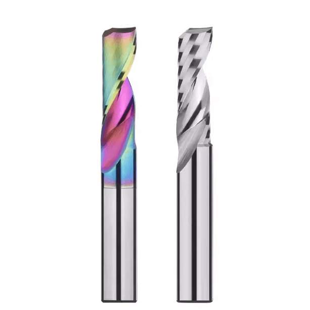
Cutting Speed Reference for Different End Mill Types
End mills come in various geometries and materials, which directly affect their cutting performance. Choosing the appropriate end mill cutting speed not only improves machining efficiency but also extends tool life. Different cutter types require different optimal speeds for roughing and finishing, making an understanding of cutting speed by end mill type essential for engineers. By comparing speed parameters of various cutters and combining them with end mill feed rate and end mill RPM calculations, engineers can determine the optimal cutting window for production.
Cutting Speed by End Mill Type
-
Flat end mills are commonly used for slotting and side milling. They support higher machining speeds and efficiency.
-
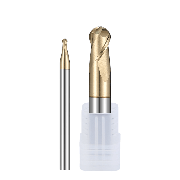
Ball nose end mills are primarily for finishing 3D surfaces. Due to the smaller contact area at the tip, lower cutting speeds are often required to prevent excessive wear.
-
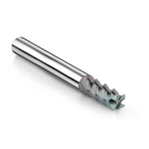
Corner radius end mills balance the efficiency of flat end mills with the smooth finish of ball nose cutters, suitable for both roughing and finishing.
When selecting cutting speeds for each tool type, engineers must consider workpiece material, tool diameter, and feed per tooth to ensure stability and surface quality.
Differences in Cutting Speeds Between Carbide and HSS Tools
Tool material significantly impacts the recommended cutting speed. Carbide end mills offer higher hardness and wear resistance, allowing higher cutting and spindle speeds, ideal for hard materials like steel, stainless steel, and titanium alloys. In contrast, HSS end mills are more cost-effective and suitable for low- to medium-speed operations, making them ideal for general steel and non-ferrous metals. Understanding how to calculate end mill cutting speed and adjusting RPM and feed rates accordingly ensures efficiency while extending tool life.
Optimizing Cutting Speeds with Coated Tools
Coatings greatly enhance tool performance:
-
TiAlN improves heat resistance, suitable for high-speed and dry cutting.
-
DLC reduces friction and BUE, allowing higher speeds when machining aluminum or copper.
-
Diamond-coated tools provide extremely long tool life on abrasive materials like graphite or carbon fiber composites.
Selecting the right coated tool combined with optimal cutting speeds improves surface finish, reduces tool changes, and lowers production costs.

How to Calculate End Mill Cutting Speed and RPM
Correct cutting speed and spindle speed are essential for extending tool life, maintaining surface finish, and improving efficiency. Incorrect parameters may lead to tool chipping, BUE, or unstable cutting. Engineers should master how to calculate end mill cutting speed and end mill RPM calculation, considering tool diameter, workpiece material, feed rate, and coating. Formulas, reference tables, or software can then determine optimal values to balance efficiency and tool life.
How to Calculate End Mill Cutting Speed (Formula and Material Reference)
Cutting speed (Vc) is usually expressed in m/min or SFM:
Vc=π×D×n1000Vc = \frac{\pi \times D \times n}{1000}
Where:
-
D = tool diameter (mm)
-
n = spindle speed (RPM)
Material-specific tables guide initial parameter selection, which can be fine-tuned based on machining conditions.
End Mill RPM Calculation
Once cutting speed is known, spindle speed is calculated as:
n=1000×Vcπ×Dn = \frac{1000 \times Vc}{\pi \times D}
Example: machining aluminum with 10 mm tool diameter at 300 m/min → n ≈ 9,550 RPM. Adjusting end mill feed rate alongside RPM ensures efficient cutting without premature tool failure.
Improving Calculation Efficiency with Software or Online Tools
CNC software, online calculators, and tool manufacturer apps can automatically provide recommended cutting speed, RPM, and feed rate based on tool geometry, material, coating, and machining method. These tools save time, reduce errors, and improve parameter accuracy, especially in mass production.

The Relationship Between Feed Rate and Tool Life
In end milling, end mill feed rate is a critical factor that directly influences tool life. Excessively high feed rates increase cutting load and vibration, which can lead to edge chipping or premature tool failure. Conversely, excessively low feed rates cause prolonged friction between the cutting edge and the workpiece, resulting in heat buildup and built-up edge (BUE), ultimately degrading surface finish.
To maximize tool life, engineers must optimize feed per tooth (Fz) based on factors such as depth of cut, width of cut, tool diameter, and spindle speed (RPM). Selecting the right feed strategy—whether high-feed milling or standard-feed milling—for each machining scenario is essential for balancing tool life and productivity.
The Effect of Depth of Cut and Width of Cut on End Mill Feed Rate
The depth and width of cut directly affect the load on the tool.
-
Greater depth of cut: Requires reducing feed rate to prevent tool overload and excessive heat accumulation.
-
Shallow depth: Allows for higher feed rates to improve efficiency.
-
Wider cut width: Increases the contact area and load on the cutting edge, leading to localized heat buildup.
In practice, engineers adjust feed rates considering tool diameter, number of flutes, and material properties to maintain stability, reduce tool wear, and ensure consistent surface quality.
How to Adjust Feed Per Tooth (Fz) to Extend Tool Life
Fz is key to controlling tool wear and surface finish:
-
Too low Fz: The cutting edge experiences frictional cutting, leading to heat accumulation and premature wear.
-
Too high Fz: Causes sudden cutting impact, which can fracture the tool edge.
The optimal Fz is selected based on end mill RPM calculation, tool diameter, and workpiece material. Fine-tuning using reference tables or calculation software allows engineers to minimize tool wear while maintaining surface quality and overall machining efficiency.
Application Scenarios for High-Feed vs. Standard-Feed Machining
High-feed machining (HFM):
-
Characterized by small depths of cut and high feed rates.
-
Ideal for roughing, removing more material per unit time, and improving production efficiency.
-
Requires stronger tool edges and higher machine rigidity.
Standard-feed machining:
-
Prioritizes tool life and surface finish.
-
Suitable for finishing or workpieces requiring high dimensional accuracy.
Engineers must flexibly select the appropriate strategy based on material, machining stage, and tool performance to achieve a balance between efficiency and tool life.

Cutting Speed and Feed Optimization Strategies for Different Materials
Optimizing end mill cutting speed and end mill feed rate for different materials has a decisive impact on tool life, surface finish, and machining efficiency. Aluminum alloys benefit from high-speed cutting and efficient chip evacuation. Stainless steel and titanium alloys require low-speed, high-torque strategies to maintain stable cutting loads. Hard materials, such as hardened steel and Inconel, demand a balance between wear resistance and thermal stability. Properly selecting end mill cutting parameters not only improves surface finish but also extends tool life and reduces overall production costs.
High-Speed Cutting Optimization for Aluminum Alloys
Aluminum alloys, due to their high plasticity and excellent thermal conductivity, are suitable for high spindle speed and high feed rate machining strategies. Using carbide end mills with a high-helix angle ensures smooth chip evacuation and reduces BUE. Maintaining a stable chip load during high-speed cutting helps achieve superior surface finishes and extend tool life. Applying coolant or MQL further enhances machining efficiency and tool longevity.
Low-Speed, High-Torque Machining of Stainless Steel and Titanium Alloys
Stainless steel and titanium alloys are difficult-to-machine materials prone to heat generation and work hardening. A low-speed, high-torque cutting strategy is recommended. Coated carbide end mills improve wear and oxidation resistance. For stainless steel, avoid excessive feed per tooth (Fz) to reduce vibration and chipping. For titanium, consider interrupted cutting and low radial engagement to minimize heat buildup and enhance tool stability.
Tips for Improving Tool Life in Hard Materials
Machining hardened steel and high-temperature alloys like Inconel is particularly challenging due to high hardness and low thermal conductivity, which concentrate heat on the cutting edge. Recommended strategies include:
-
Low spindle RPM and small axial depth of cut
-
Use of PCD tools, CVD diamond-coated tools, or carbide tools with high-wear-resistant coatings
-
Proper feed per tooth adjustment
-
High-pressure coolant or air cooling for efficient chip removal
These measures help extend tool life, reduce machining costs, and are critical in aerospace and mold manufacturing.

Common Mistakes and Optimization Suggestions
Even with high-quality tools, improper cutting parameter settings can reduce tool life and surface quality. Common mistakes include excessive cutting speeds, insufficient feed rates, and improper coolant or toolpath strategies. Identifying these issues and implementing corrective measures improves machining stability, surface finish, and overall tool efficiency.
Premature Tool Failure Due to Excessive Cutting Speeds
High cutting speeds increase friction and temperature at the cutting edge, reducing tool hardness, softening edges, and causing chipping. Tool coating wear is accelerated, degrading surface finish. Engineers should consider tool type, material, depth of cut, end mill RPM, and feed per tooth to avoid premature failure.
Friction and Built-Up Edge from Insufficient Feed
Low feed rates prolong contact between the tool edge and workpiece, increasing heat and built-up edge (BUE) formation. This degrades surface quality and accelerates tool wear. Properly setting end mill feed rate and feed per tooth, in combination with cutting speed, balances cutting load and heat, reducing friction and BUE.
Proper Use of Coolant and Toolpath Strategies
Effective cooling reduces friction and heat, extending tool life. For hard or difficult materials, use high-pressure coolant, MQL, or air cooling. Optimize toolpaths through layered cutting, reduced cut widths, and ramping to minimize load, vibration, and cutting shock, improving both tool longevity and surface finish.

Conclusion and Practical Recommendations
End mill cutting speed and feed rate are key factors affecting tool life, surface quality, and productivity. Optimal parameters depend on tool type, coating, material, and workpiece geometry. Proper RPM calculation, feed per tooth, and depth/width adjustments are essential. Avoid common mistakes, apply coolant and toolpath optimizations, and adjust parameters dynamically during roughing and finishing to balance tool life and productivity.
How to Adjust Machining Parameters Based on End Mill Cutting Speed and Feed Rate
Select the appropriate cutting speed by end mill type based on material, tool, and coating. Fine-tune end mill feed rate and feed per tooth using RPM calculations, manufacturer data sheets, or online calculators. Adjust depth and width of cut dynamically according to the machining stage to balance tool load, heat, and surface quality.
The Key to Balancing Tool Life and Productivity
By optimizing cutting speed, feed rate, and depth of cut, engineers can achieve high machining efficiency while preserving tool life. Using high-feed milling and optimized toolpaths (layered, ramping/slope cutting) ensures rapid material removal during roughing and low load with high surface quality during finishing.
Future Trend: Intelligent Cutting Parameter Optimization
Smart manufacturing and Industry 4.0 will increasingly rely on real-time monitoring of cutting forces, temperature, and vibration to adjust end mill cutting speed and feed rate automatically. Integration of AI-based tool life prediction, intelligent toolpath optimization, and adaptive machining will enhance productivity and part quality while minimizing human error.