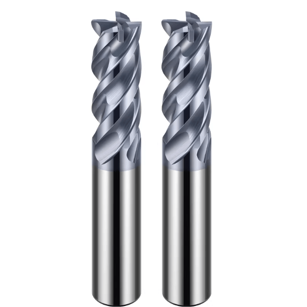
As precision machining and batch production continue to prioritize efficiency and quality, custom milling cutters have become a strategic tool for CNC machining companies seeking a competitive edge. Unlike standard tools, custom solutions are specifically engineered to suit unique workpiece materials, complex geometries, or specialized processes—significantly improving cutting efficiency, dimensional accuracy, and tool life.
Whether you’re a CNC engineer, a shop floor technician, or a tool procurement manager, clearly and accurately specifying your custom carbide cutter requirements is essential to achieving optimal results, reducing lead times, and avoiding costly rework or mismatches.
However, many companies struggle to articulate their requirements when communicating with custom tool manufacturers. Vague specifications or incomplete parameter descriptions often lead to poorly matched tools, production delays, and unnecessary expenses—especially when it comes to high-performance custom carbide end mills.
To avoid these pitfalls, it’s critical to approach custom tooling with a structured, detail-driven mindset—one that covers application scenarios, tool geometry, substrate materials, coatings, and machine compatibility.

Why Choose a Custom Milling Cutter?
As modern manufacturing grows more complex, standard milling cutters are no longer sufficient to meet all machining demands. From high-hardness alloys to intricate 3D contours, and from miniature parts to large structural components, diverse applications require tools beyond the “one-size-fits-all” solutions of standard offerings. Custom milling cutters offer a tailored approach to increase machining efficiency, achieve tighter tolerances, and meet the rigorous demands of advanced manufacturing.
By customizing tool geometry, substrate material, and coatings, manufacturers can optimize performance for their specific application—enhancing stability, accuracy, and cost-effectiveness throughout the CNC workflow.
Limitations of Standard Milling Tools
While standard end mills offer faster delivery and lower upfront costs, their generic design can severely limit performance in challenging conditions. When processing advanced materials such as titanium alloys, Inconel, or carbon-fiber composites, standard tools often suffer from premature wear, increased vibration, and poor surface finish.
Standard tools lack the performance customization necessary for high-precision or high-volume operations, especially in aerospace, automotive, and mold manufacturing where performance, consistency, and reliability are critical.
Advantages of Custom End Mills
Custom CNC milling cutters deliver superior adaptability and processing stability by tailoring their design to actual working conditions—including feed rates, cooling strategies, and spindle speeds. The main advantages include:
-
Higher Machining Efficiency: Custom edge profiles and flute counts can significantly increase the material removal rate (MRR).
-
Improved Accuracy and Surface Quality: Purpose-built tools reduce the need for secondary operations or manual finishing.
-
Extended Tool Life: High-performance substrates (e.g., micro-grain carbide) and coatings are selected for superior wear resistance.
For operations requiring multiple processes, a multi-functional custom cutter can be designed to reduce tool changes and streamline automation.
Ideal Applications for Custom Tools
Custom milling cutters are especially valuable in the following scenarios:
-
Mold Machining with Complex 3D Contours: Automotive mold cores, 3C product shells, and intricate surface profiles.
-
Machining Hard-to-Cut Materials: Stainless steel, titanium alloys, and ceramics benefit from specialized geometries and coatings.
-
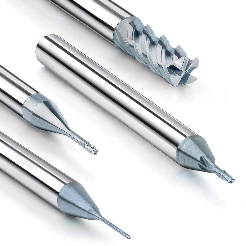
Micro-Feature Machining: Ideal for medical components or miniature engraving tools.
-
Dedicated Line Production: Custom tools enable repeatable, efficient, and stable performance across large-scale operations.
For example, a deep-cavity custom carbide end mill for titanium alloy can be designed with reinforced cutting edges and optimized flute geometry—significantly reducing cutting forces and chatter, while ensuring part integrity.

5 Core Parameters You Must Specify When Ordering Custom Tools
To ensure a successful custom tool project, it’s critical to provide manufacturers with complete and accurate specifications. Doing so avoids unnecessary design iterations and production delays. The following five parameters form the foundation for custom cutter design:
1. Workpiece Material & Machining Conditions
Start with the material you’re cutting—this directly affects tool geometry, substrate selection, and coating choice. Different materials demand very different tool designs:
-
Aluminum Alloys: Require sharp geometries for chip evacuation and anti-adhesive coatings.
-
Titanium Alloys / Stainless Steel: Need heat-resistant tools with high rigidity.
-
Hardened Steels (≥50 HRC): Demand wear-resistant materials and tough edge design.
Include relevant details such as:
-
Material code (e.g., SUS304, Ti-6Al-4V)
-
Hardness (HRC)
-
Cutting strategy (roughing, finishing)
-
Coolant method (dry, flood, MQL)
2. Tool Dimensions (D1, L2, L1, D2)
Tool size impacts rigidity, cutting performance, and compatibility with your machine. Be sure to specify:
-
Cutting Diameter (D1): Influences toolpath and must align with CAD geometry.
-
Flute Length (L2): Matches actual cutting depth—longer tools can cause deflection and vibration.
-
Overall Length (L1): Must fit within the machine’s tool change and clearance constraints.
-
Shank Diameter (D2): Must match your toolholder type (ER collet, thermal shrink, etc.).
It’s best to provide a detailed drawing or parameter sheet to avoid misinterpretation.

3. Tool Substrate (Carbide Grade)
The base material directly affects cutting strength, thermal resistance, and longevity. Most custom tools use micro-grain or ultra-fine cemented carbide, which is suitable for high-speed and dry machining.
General guidelines include:
-
For Hardened Steel: Use ultra-hard carbide with fine grain size.
-
For Aluminum or Copper Alloys: Use high-toughness, low-helix-angle carbide.
-
For High-Load Applications: Consider substrate treatments like nitriding or ultrasonic surface enhancement.
Select carbide grades by application, e.g., K10, K20, UF, or sub-micron carbide classifications.
4. Coating Type (TiAlN, DLC, CVD, etc.)
Coatings enhance performance, heat resistance, and surface finish. The right coating improves durability and reduces friction. Popular choices include:
-
TiAlN: Ideal for dry machining of high-temperature alloys and hardened steel.
-
DLC (Diamond-Like Carbon): Excellent for aluminum, copper, and carbon composites.
-
CVD Diamond Coating: Excellent for abrasive and hard materials but requires substrate compatibility.
Choose your coating based on specific cutting conditions—RPM, feed rate, coolant—and consider multi-layer composite coatings if needed.
5. Machine & Tool Holder Compatibility
Machine tool and holder data are often overlooked—but are critical to custom tool success:
-
Machine Type: Vertical vs. horizontal vs. 5-axis systems influence tool overhang and interference clearance.
-
Holder Type: Shrink-fit, hydraulic, or ER collets determine shank specs and runout tolerances.
-
Tool Changer Constraints: Influence tool length, balance, and weight distribution.
Always specify the spindle type, clamping system, and any machine-specific requirements.

How to Communicate Effectively with Custom Tool Manufacturers
Even with a solid internal plan, poor communication with your tool supplier can lead to mistakes, delays, or unsatisfactory tool performance. Here’s how to streamline collaboration and ensure successful results:
Providing Clear Drawings and Schematics
A complete technical drawing is the core of your tool design request. Use 2D CAD files or 3D formats (e.g., STEP or IGES), including:
-
Tool geometry (flute count, helix angle, end shape).
-
Dimensions (cutting diameter, flute length, total length, shank diameter).
-
Special features (step-downs, ball nose, corner radius).
-
Section views or detailed annotations for complex elements.
-
Application overview: Material, depth of cut, and toolpath type.
Even hand-drawn sketches can work if supplemented with three-view drawings and clear notes.
Focus Areas: Tolerances, Cutting Depth, Chamfers
Often overlooked, these details can make or break tool performance:
-
Dimensional Tolerances: Specify critical tolerances, especially for shank and cutting diameter (e.g., ±0.01 mm).
-
Effective Cutting Depth: Determines flute geometry and vibration behavior.
-
Chamfer or Radius Requirements: Clarify sharp edge protection, exit chamfers, or edge rounding.
Use standardized notation (e.g., R0.2, 90°×0.3) to ensure direct CNC programming compatibility.
Sample Testing and Pilot Production
Even with great planning, real-world testing is critical. For complex or high-risk applications:
-
Initial Prototypes: 2–3 samples for test cutting and feedback.
-
Process Feedback: Collect data on RPM, feed, surface finish, wear rates.
-
Pilot Batch Runs: 10–50 pieces to validate stability before mass production.
This method is especially useful for materials like titanium, heat-treated steel, or aluminum alloys—where tool failure is costly.

Avoiding Common Mistakes in Custom Tool Projects
Customized end mills can meet special processing requirements, but in actual operation, customization failures due to insufficient communication or inaccurate technical parameters are common. To achieve efficient customized tool development, it is crucial to identify and avoid these common errors and communication blind spots. The following is a detailed analysis of the common problems encountered in the customization process and avoidance strategies to help the customization project land smoothly.
Ambiguous Technical Parameters
Incomplete or vague specs lead to incorrect tool designs. Common issues include:
-
Missing flute count or helix angle.
-
Lack of tolerance data or cutting depth info.
-
No clear material or hardness data.
Use specification sheets and accurate drawings. Target SEO terms like “custom carbide end mills specification guide” can help users find proper resources.
Ignoring Cutting Parameters and Spindle Speed
Cutting conditions—RPM, feed rate, depth of cut—impact tool life and quality. If not provided, manufacturers can’t optimize edge geometry or coating.
Always share machine RPM range and material characteristics. Match tool design to real-world CNC environments.
Overlooking Coating Impacts
The coating is more than a surface layer—it dictates heat dissipation, chip flow, and tool longevity. Skipping this step often results in tools that wear prematurely or damage workpieces.
Clarify coating requirements with performance goals. For example, DLC for aluminum, TiAlN for hardened steel, or CVD for abrasives.
Not Specifying Use Environment (Dry, Wet, High-Speed)
Different environments require different tools. Dry cutting needs thermal-resistant tools; wet machining requires corrosion-resistant coatings; high-speed applications need stronger geometries.
Always communicate cooling method, speed, and machine capabilities. This helps your manufacturer tailor the ideal cutter.

Custom Milling Cutters Are a Long-Term Investment
Custom end mills are not just a tactical purchase—they’re a strategic investment in your productivity and product quality. With clear requirements, strong technical guidance, and reliable communication, you can achieve long-term savings and consistent machining excellence.
Choose Experienced Custom Tool Manufacturers
Working with a skilled tool supplier ensures your custom solution meets expectations. Expert manufacturers offer more than production—they advise on geometry, material, and coating selection to maximize tool life and ROI. Their experience reduces risk and shortens lead times.
Full Communication + Sample Validation = Proven Success
The key to a successful custom cutter project is consistent communication and real-world validation. Provide complete specs—machine type, RPM, coolant type, cutting parameters—and insist on sample testing before scaling. This process ensures the final tool performs as expected and supports your production goals.
This “full communication + trial cutting” approach is a proven path to greater machining efficiency, better part quality, and superior ROI on your custom milling tools.