In modern CNC machining, aluminum alloys are widely used in aerospace, mold making, automotive parts, and other industries due to their lightweight nature, excellent thermal conductivity, and low cutting resistance. However, aluminum machining at high speeds often faces challenges such as built-up edge (BUE), tool adhesion, and poor chip evacuation. Balancing surface finish, tool life, and machining efficiency remains a primary concern for manufacturers.
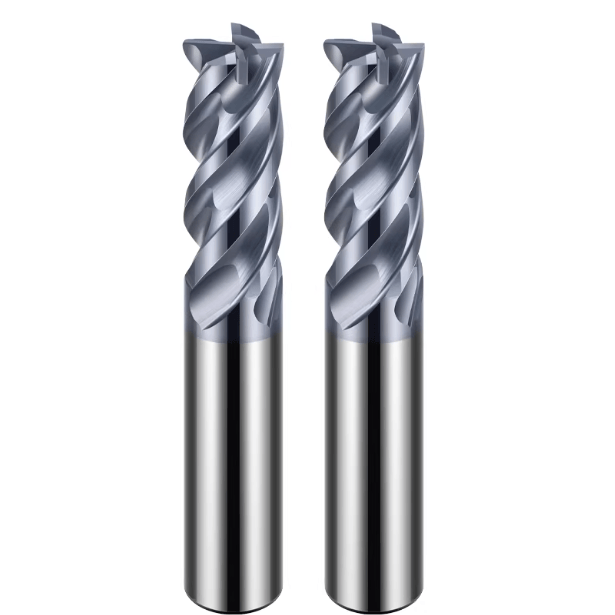
As a versatile tool well-suited to aluminum machining, the square end mill plays a crucial role in roughing, finishing, and planar milling operations. Particularly, the carbide square end mill for aluminum stands out by combining exceptional wear resistance with high-speed machining capabilities, significantly improving cutting efficiency.
It is important to note that tool performance depends not only on material and geometric design but also heavily on toolpath strategy. Well-planned toolpaths reduce cutting forces, enhance chip evacuation, and extend tool life. When paired with a 3 flute square end mill for aluminum, scientific toolpath strategies enable both high material removal rates and superior surface quality.
This article explores common toolpath strategies for aluminum machining, correlating tool geometries with path optimizations to maximize the performance of flat-bottom milling cutters. Whether aiming to increase throughput or improve machining stability, these approaches offer practical insights and technical guidance.

The Key Role of Flat-Bottom Milling Cutters for Aluminum in Machining
Why Choose a Square End Mill for Aluminum?
Square end mills are widely used in aluminum CNC machining due to their simple structure and compatibility with diverse toolpaths. Compared to ball or round nose cutters, flat-bottom mills provide a stable cutting load distribution on both the end face and side edges, making them especially effective for contouring, planar milling, and slotting.
The relatively low strength and high ductility of aluminum alloys favor the use of right-angle cutting edges, which help improve the quality of machined bottom surfaces.
For production environments demanding high efficiency, flat-bottom mills with sharp cutting edges and wide chip gullets reduce cutting resistance, enhancing both productivity and surface finish. Under high-speed machining (HSM) conditions, combined with optimized toolpaths, these cutters minimize heat buildup and extend tool life.
Common Aluminum Alloy Processing Challenges: Built-Up Edge, Rough Surface, and Poor Chip Removal
Though aluminum offers low cutting resistance, its material properties pose specific challenges. Built-up edge (BUE) is a prevalent issue, where chips adhere to the cutting edge, disrupting smooth cutting, accelerating tool wear, and potentially damaging the workpiece surface. BUE formation accelerates especially under dry cutting or inadequate cooling.
Additionally, the thin, stringy chips typical in high-speed aluminum machining can clog the tool’s flutes if not evacuated promptly, leading to poor chip removal, increased cutting temperatures, tool sticking, and degraded surface finish. Selecting tools with large helix angles and polished flute designs, combined with effective cooling or minimum quantity lubrication (MQL), effectively addresses these issues, improving surface quality and machining stability.
Impact of Tool Structure on Performance: Number of Flutes, Helix Angle, and Flute Design
Tool geometry plays a vital role in aluminum machining, particularly for carbide square end mills. Appropriate design significantly enhances performance.
-
Number of Flutes: The 3-flute design is mainstream for high-speed aluminum cutting. Compared to 2- or 4-flute cutters, 3-flute mills balance chip evacuation and cutting strength, achieving smoother cutting under high speeds.
-
Helix Angle: High helix angles (40°–45°) improve chip evacuation and reduce adhesion in aluminum cutting.
-
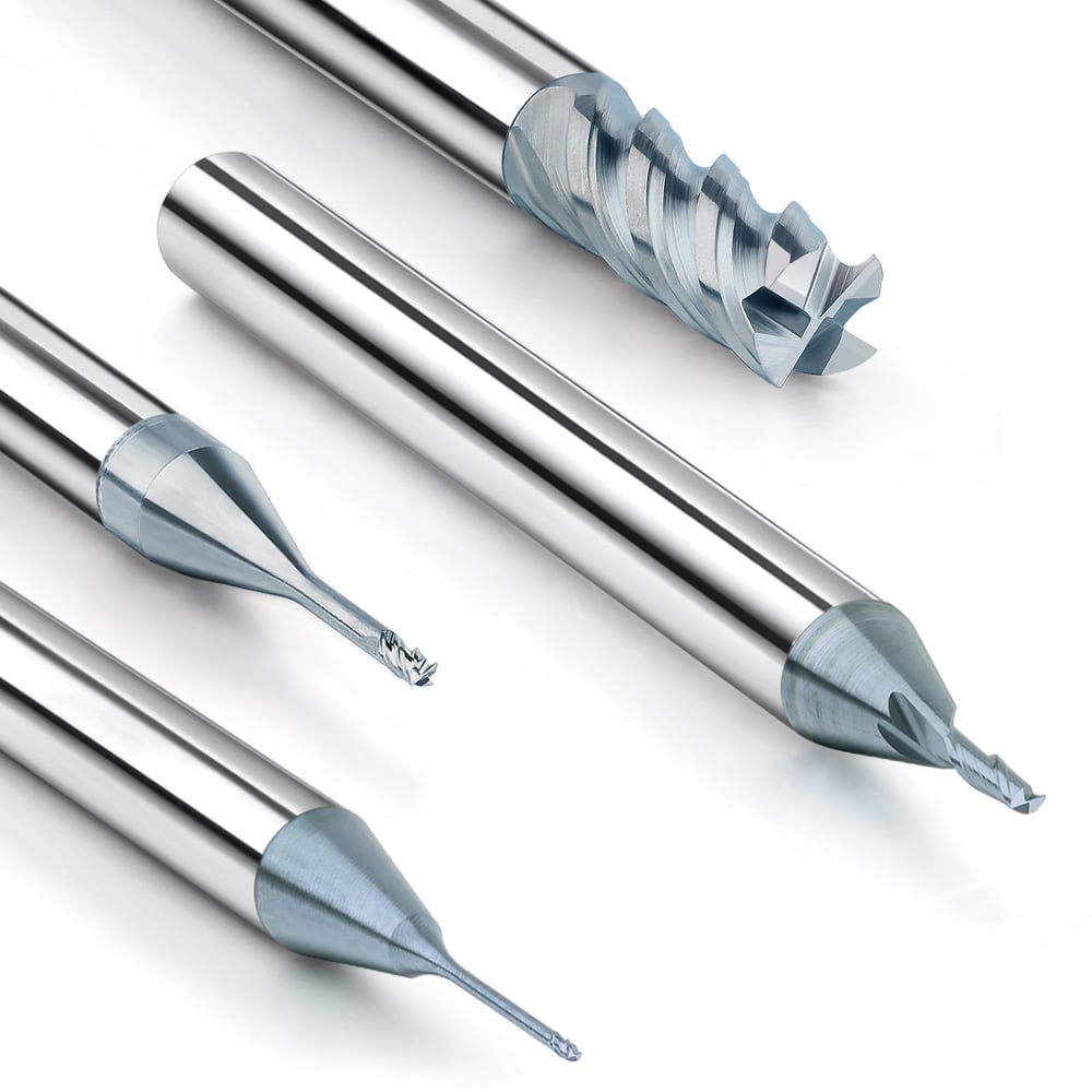
Flute Surface: Mirror-polished or electropolished flutes minimize chip friction, maintaining thermal stability during extended cutting.
Advanced tools may include micro chip breakers at the flute base, refining chips and preventing long chips from wrapping around the cutter. Combined with 3 flute square end mill bits for aluminum, this design improves chip flow and machining efficiency, especially during heavy roughing with large depths and high feed rates.

The Impact of Path Strategy on the Performance of Flat-Bottom Milling Cutters for Aluminum
Traditional Paths vs. Efficient Paths (HSM, Adaptive) and Their Impact on Tool Life
Path strategy significantly influences tool life and machining stability. While traditional methods like zigzag roughing or single-pass side milling are easy to program, they cause sudden cutting load changes, especially at corners or feed points, increasing localized wear and chipping risk.
Efficient path strategies—such as high-speed machining (HSM) and Adaptive Clearing—dynamically adjust feed trajectories to maintain a constant chip load. This stable load enables carbide square end mills for aluminum to operate under balanced conditions, extending tool life and improving chip evacuation.
When combined with 3 flute square end mill bits for aluminum for high-speed processing, these strategies reduce heat buildup and cutting shocks, prevent chip adhesion caused by material softening, and fundamentally optimize the aluminum machining process.
Controlling Depth of Cut and Side Milling Width to Improve Efficiency
Axial depth of cut (ap) and radial width of cut (ae) directly determine instantaneous cutting load and are critical for balancing efficiency and tool wear.
For carbide square end mills for aluminum, a roughing strategy combining a larger axial depth (≥1D) with smaller radial step-over (10–20% of tool diameter) alongside adaptive toolpaths stabilizes cutting forces and leverages carbide’s chipping resistance. Finishing passes reduce depth (<0.3D) and step-over to improve surface finish.
Complex contours or internal corners require careful path setup to avoid local re-cutting and overlap, which accelerate tool wear. Utilizing automated step control or process simulation to assess path coverage helps maximize machining efficiency and tool life for 3 flute square end mills.
Path Optimization Techniques to Prevent Tool Vibration and Chipping
Aluminum’s toughness and thermal conductivity make tool vibration and uneven wear likely with poor path design. High-speed or long overhang cutting especially risks tool breakage or micro cracks.
Recommendations:
-
Use spiral or ramp entry to avoid instantaneous full-tooth engagement shocks.
-
Minimize sharp corners or replace with arc transitions for smoother directional changes.
-
In long overhangs, use consistent direction milling and controlled retract distance to reduce vibrations.
-
Prioritize symmetrical load distribution in paths when using 3-flute cutters to suppress resonance.
-
Combine segmented toolpaths with dynamic feed control to mitigate localized tool fatigue, critical for slender 3 flute square end mill bits for aluminum.

Choosing the Right Tool and Cutting Parameters
Why Use Carbide Square End Mills for Aluminum?
Tool material directly affects cutting efficiency and tool life. Carbide square end mills for aluminum have become the preferred choice due to superior hardness, thermal conductivity, and edge stability. Compared to HSS, carbide better withstands the heat from high-speed aluminum cutting, reducing wear and maintaining stability.
Long-duration, high-speed aluminum machining demands tools with excellent thermal management and structural integrity to prevent built-up edge, edge dulling, and breakage. Many dedicated carbide aluminum mills feature polished flutes, large helix angles, and mirror finishes, enhancing chip flow and anti-adhesion, ideal for efficient cutting.
How to Choose Between 3-Flute and 4-Flute Square End Mills?
Flute count depends on machining conditions. The 3 flute square end mill is ideal for high-speed roughing and large chip loads, offering larger flute volume for efficient chip evacuation and reduced clogging, minimizing built-up edge risks.
For thick sections or deep cuts, 3-flute tools provide better cutting feel and higher metal removal rates. They also generate lower cutting forces and vibration at high spindle speeds.
For semi-finishing or finishing requiring higher surface accuracy, 4-flute square end mills deliver more cutting edges per revolution, increasing feed per minute and surface quality, though with reduced chip space.
Choosing depends on spindle speed, material, cycle time, cooling, and is best optimized via trial or software simulation.
Recommended Cutting Parameters and Cooling Methods
For aluminum, proper cutting parameters maximize tool performance and part quality:
-
Spindle Speed (RPM): 12,000–25,000 rpm, adjusted per tool diameter and machine.
-
Feed Rate: 1,500–4,500 mm/min; higher feed recommended for 3-flute tools.
-
Feed per Tooth (fz): 0.04–0.10 mm/tooth; higher for roughing, lower for finishing.
-
Axial Depth of Cut (ap): 0.5D–1.0D roughing; <0.2D finishing.
-
Radial Step-over (ae): 10–25% of tool diameter for smooth cutting and chip evacuation.
Cooling methods:
-
Flood coolant (water-soluble) for most cases.
-
Minimum quantity lubrication (MQL) for high-speed or high-gloss finishes.
-
Compressed air for dry high-speed machining, ensuring effective chip evacuation.

Advantages and Path Matching Skills of 3-Flute Flat End Mill Bits for Aluminum
Performance of 3 Flute Square End Mill Bits for Aluminum in High-Speed Machining
In high-speed machining of aluminum alloys, 3 flute square end mill bits for aluminum have become the preferred high-efficiency tool in the CNC industry due to their excellent chip evacuation, rigidity, and cutting balance. Compared with 2-flute cutters, 3-flute tools allow a higher feed per tooth (fz), enabling stable cutting at high spindle speeds and increasing material removal rate (MRR) per unit time. Compared with 4-flute cutters, their larger flute volume reduces the risk of chip clogging, ensuring smooth chip flow during prolonged continuous machining.
Operating at high speeds (12,000–25,000 RPM), the 3-flute design offers more balanced cutting force distribution, reducing spindle axial vibration and minimizing the chances of chipping or tool breakage. Moreover, 3-flute aluminum cutters typically feature high helix angles (e.g., 45°) and mirror-polished flutes, enhancing chip evacuation and cutting smoothness. These features contribute to excellent machining stability and superior surface finish when working with soft metals such as aerospace-grade aluminum and mold alloys.
How to Use 3-Edge Design to Improve Chip Removal Efficiency and Surface Quality
The primary advantage of 3-flute tools lies in their optimized geometry, which provides ample chip evacuation space. In aluminum machining, chips are generated rapidly and in large quantities. Poor chip evacuation leads to built-up edge (BUE), adversely affecting tool life and surface quality. The 3-flute design’s spacious flutes effectively prevent chip accumulation, jamming, and tool sticking.
Additionally, the 3-flute configuration balances the number of cutting edges per spindle revolution, optimizing feed efficiency and cutting load. This not only extends tool life but also improves surface finish. When combined with Z-direction ramping or spiral interpolation feed techniques, impact forces caused by instantaneous full-tooth engagement are minimized, reducing corner vibration and burr formation.
High-end 3-flute aluminum flat end mills may also incorporate electro-polished flutes, asymmetric tooth pitch, and anti-resonance features to enhance cutting stability and self-cleaning ability. Such designs maintain efficient chip evacuation and stable cutting even under dry or minimal lubrication (MQL) conditions.

Typical Path Case Sharing for 3f Square End Mill
To maximize the capabilities of a 3f square end mill for aluminum, the toolpath strategy should align with its geometric features. Below are common application cases:
-
Adaptive Clearing (Adaptive Roughing)
Ideal for rough milling large workpieces. Employ a small radial step-over (ae = 10–15%) combined with a large axial depth (ap = 1.0D), high spindle speeds (>18,000 RPM), and medium-to-high feed rates (3,000–5,000 mm/min). This maintains constant cutting load for high-speed material removal with efficient chip evacuation. -
Z-Level Finishing
Best suited for aluminum cavities and mold boundaries. Maintaining a shallow cutting depth (ap < 0.2D), the 3-flute tool delivers consistent contour accuracy and excellent surface finish. -
Fine Contouring
For demanding surface finishes (e.g., mirror-polished aluminum), use 3-flute tools with minimal radial step-over (ae < 5%), stable feed rates, and effective cooling such as MQL or high-pressure air. This approach significantly reduces surface roughness to Ra < 0.4 μm.
By combining these path strategies with the 3-flute cutter’s design, users can achieve fast roughing and maintain excellent surface quality and tool life during finishing, thereby improving overall machining efficiency and cost control.

Common Misunderstandings and Path Optimization Suggestions
Excessive Cutting Leads to Premature Tool Wear
In aluminum machining, operators often prioritize speed over cutting parameter control, resulting in excessive cutting loads. Too large an axial depth of cut (ap) or radial step-over (ae) causes sudden spikes in cutting forces, accelerating wear or causing chipping of carbide tools. In severe cases, it can lead to premature tool fatigue failure.
Especially when machining with carbide square end mills for aluminum at high speeds, exceeding cutting parameters not only shortens tool life but also promotes chip clogging and BUE formation, degrading surface finish. It is advisable to avoid excessive one-pass cuts by applying proper machining allowances and layered finishing strategies to enhance tool life and machining stability.
Path Overlap and Improper Entry/Exit Cause Chipping
Overlapping toolpaths excessively or using inappropriate entry/exit moves are common causes of tool edge chipping. Excessive overlap concentrates cutting loads on the same tool area repeatedly, causing localized heat buildup and stress that fracture the cutting edge.
Likewise, aggressive entry or exit motions, such as rapid linear plunging or abrupt stops, induce tool vibration and impact, reducing cutting stability. To mitigate these risks, utilize smooth spiral or ramp feeds and avoid sharp corners in toolpath designs.
Pre-evaluating cutting load distribution via toolpath simulation software allows adjustment of overlap and entry/exit trajectories, significantly reducing path-induced tool damage and extending the service life of aluminum flat end mills.
Reasonable Use of Spiral Feed and Equal-Height Roughing Strategies
Spiral feed techniques are widely adopted in aluminum machining for progressive cutting, reducing instantaneous load and avoiding full-tooth simultaneous engagement. Properly setting spiral angles and feed rates enhances tool longevity and machining stability.
Equal-height roughing removes material in uniform layers, ensuring consistent cutting volume and chip load per pass, preventing load spikes from complex geometries. This strategy pairs well with 3- or 4-flute carbide aluminum flat end mills, improving surface consistency while maintaining efficiency.
When combined with optimized cutting parameters and cooling methods, these path optimizations effectively lower chipping risks and premature wear, enhancing overall aluminum machining quality and productivity.

Path Strategy + High-Quality Tools = Maximized Aluminum Processing Efficiency
The efficiency and stability of aluminum machining depend heavily on the synergy between advanced toolpath strategies and premium tooling. As discussed, selecting the right square end mill for aluminum, especially carbide variants, substantially improves wear resistance and chip evacuation, preserving edge sharpness and machining stability.
Path optimizations tailored for aluminum—such as efficient HSM and Adaptive Clearing paths, controlled cutting depths and step-overs, and spiral and equal-height roughing methods—reduce cutting load fluctuations, tool vibration, and chipping risk, extending tool life and enhancing surface finish.
In particular, 3-flute aluminum flat end mills excel with superior chip removal and cutting force balance, achieving ideal high-speed machining results when matched with scientific toolpath planning. Conversely, path design errors—over-cutting, excessive overlap, or poor tool entry/exit—exacerbate tool wear and reduce process stability and cost-effectiveness.
Therefore, machining engineers and operators should carefully consider their equipment, workpiece, and production goals, deeply understand the relationship between tool geometry and path strategy, and combine advanced tool selection with optimized toolpaths to maximize aluminum machining performance and competitiveness.