PCB cutting tools are essential in electronics manufacturing and PCB processing. Their performance directly affects cutting precision, tool life, and production efficiency. Whether performing micro-milling on high-density multi-layer boards or depaneling standard single-sided PCBs, engineers may encounter issues such as rapid tool wear, edge burrs, chipping, and reduced machining accuracy. These challenges not only slow down production but also increase scrap rates and overall costs.
This article provides a detailed analysis of common problems with PCB cutting tools and offers targeted solutions based on different tool types, including V-type cutters, routing cutters, and tungsten carbide PCB cutting tools. It also explores how PCB cutting tools compare with traditional end mills, strategies for tool selection, and effective maintenance methods to extend tool life. Understanding these factors helps engineers optimize board depaneling techniques, improve cutting quality, and enhance production efficiency.
What is a PCB Cutting Tool?
A PCB cutting tool is a high-precision tool specifically designed for printed circuit board (PCB) processing and depaneling. These tools enable precise cutting, depaneling, slotting, and chamfering on PCBs of various materials and thicknesses. PCB cutting tools directly affect edge quality, dimensional accuracy, and production efficiency. Common types include V-cutters, routing cutters, micro-milling cutters, and tungsten carbide PCB cutting tools, each optimized for specific processes. Understanding what a PCB cutting tool is and its applications is critical for engineers seeking to improve PCB processing efficiency and product quality.
Definition and Function of PCB Cutting Tools
PCB cutting tools are designed for depaneling, slotting, and micro-milling, with a primary goal of achieving high-precision, low-burr PCB processing. Compared to traditional end mills, they are optimized for PCB characteristics such as glass fiber reinforced epoxy boards and high-density multi-layer boards (HDI PCBs), featuring specialized tool geometry, cutting angles, and materials. Proper use reduces cutting stress, extends tool life, ensures smooth edges, and improves hole placement accuracy, minimizing scrap and boosting efficiency.
Application Scenarios of PCB Cutting Tools in Electronics Manufacturing
PCB cutting tools are widely applied across various PCB processing steps:
-
Panel splitting: Cutting large boards into individual PCBs with smooth, burr-free edges.
-
Slotting and chamfering: Machining precise traces or component mounting areas to ensure assembly accuracy.
-
Micro-milling: Drilling through-holes and cutting fine lines in multi-layer high-density boards, requiring high tool rigidity and excellent wear resistance.
Selecting the appropriate tool type and material based on PCB type, thickness, and required precision is critical for optimizing these processes.
Overview of Common Materials and Tool Types
Materials:
-
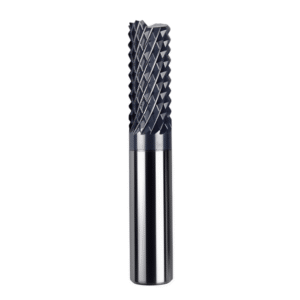
Tungsten carbide: High hardness and excellent wear resistance, ideal for high-density, multi-layer PCBs.
-
HSS: Suitable for standard PCBs, lower cost, limited wear resistance.
Tool Types:
-
V-Cutter: Depaneling and cutting right-angle grooves, providing smooth edges for high-precision processing.
-
Router Bit: Slotting, chamfering, and fine trace cutting across a wide range of PCB types.
-
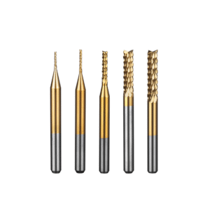
Micro End Mill: Ideal for high-density, multi-layer PCBs or fine traces, requiring high rigidity.
-
Specialty Tools: Chamfering cutters, ball-nose cutters, and coated cutters for specific processes.
Choosing the right combination of tool type, material, and cutting parameters ensures precise cuts, minimizes burrs, and extends tool life.
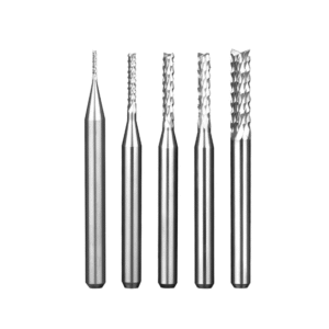
Types of PCB Cutting Tools
PCB cutting tools vary in structure, material, and purpose. Engineers must select tools based on PCB material, thickness, precision, and processing technology to ensure smooth edges, minimize burrs, achieve high accuracy, and extend tool life. Common types include V-cutters, routing cutters, micro-milling cutters, and specialty tools, each with unique advantages for depaneling, slotting, chamfering, or precision circuit processing.
V-Cutter
V-cutters are primarily used for depaneling and cutting right-angle grooves. The V-shaped tip creates precise cut lines while reducing burrs and debris. They are suitable for standard single-sided boards, multi-layer HDI PCBs, and precision circuit boards. Selecting the correct V-angle and tip diameter based on board thickness, hardness, and cutting speed ensures optimal edge quality and tool longevity.
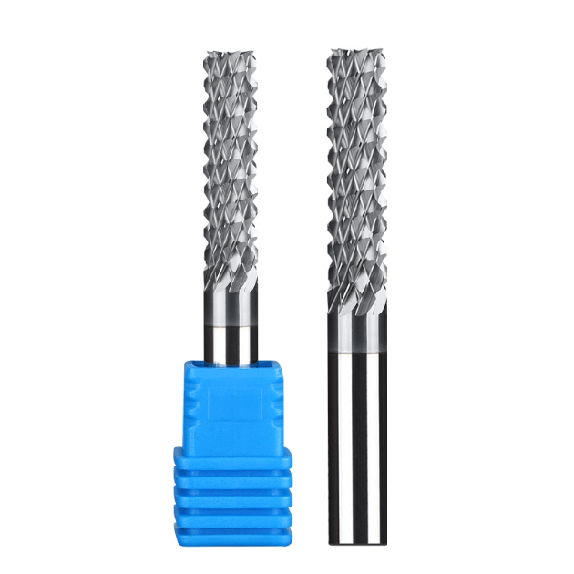
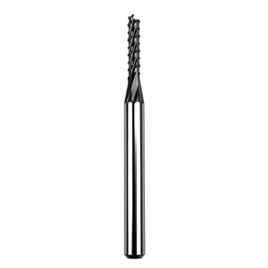
Router Bit
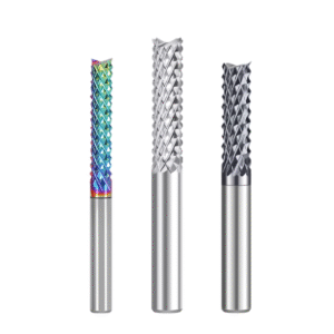
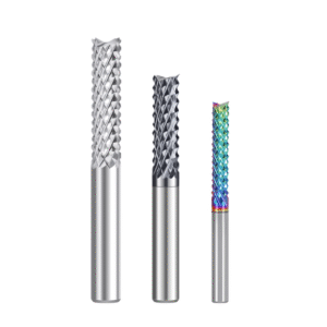
Router bits are versatile tools for grooving, chamfering, and complex circuit shapes. They come in various blade profiles to handle different PCB thicknesses and materials. Tungsten carbide or HSS router bits improve processing efficiency, maintain precision, and reduce tool wear when selected appropriately.
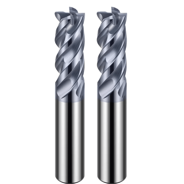
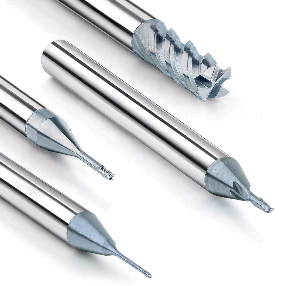
Micro-Milling Cutters and Tungsten Carbide PCB Cutting Tools
Micro-milling cutters are essential for multi-layer, high-density PCBs and fine traces, requiring extreme rigidity and wear resistance. Tungsten carbide cutters excel in these applications, offering high hardness, long tool life, and precise cuts. Matching tool diameter, flute count, and cutting parameters prevents edge chipping, burrs, and overheating, improving both productivity and finished product quality.
Other Specialty Tools
Specialized cutters, including chamfering cutters, ball-nose cutters, and coated cutters, address specific processing needs such as component mounting edges, micro grooves, or extended tool life. Proper selection reduces scrap and lowers production costs.
PCB Cutting Tool vs End Mill
Selecting the right tool is crucial for precision, productivity, and tool life. PCB cutting tools differ from end mills in structure, cutting method, applicable materials, and processing techniques.
Differences in Structure and Cutting Methods
PCB cutting tools feature tip geometries optimized for boards (V-tip, micro-milling angles) for depaneling, slotting, and chamfering. End mills are cylindrical with thicker cutting edges, suited for metals and general materials.
-
PCB cutting tool: Sharp edges, small tips, high rigidity; suitable for thin or multi-layer PCBs, reducing burrs and ensuring precision.
-
End mill: Large diameter, thick edge; good for rough machining but prone to burrs and inaccuracies on PCBs.
Comparison of Applicable Processes and Materials
-
PCB cutting tools: Glass-fiber epoxy boards, multi-layer HDI boards, aluminum-based PCBs; used for depaneling, slotting, chamfering, and fine circuit cutting.
-
End mills: Metals, plastics, thick plates; mainly used for roughing.
PCB cutting tools improve edge quality and precision, reducing breakage and scrap, unlike end mills in high-precision PCB applications.
Cost and Life Analysis
PCB cutting tools, usually tungsten carbide, have higher unit costs but lower overall production costs due to longer life, higher accuracy, and lower scrap rates. End mills wear faster, chip, and produce burrs in precision PCB processing, increasing rework and waste. Optimizing cutting speed, feed, and cooling maximizes PCB tool life and processing efficiency.
Common Problems and Causes of PCB Cutting Tools
Even with high-precision PCB cutting tools, problems like tool wear, burrs, breakage, and reduced machining accuracy can occur. These issues affect board separation accuracy, production efficiency, and material waste. Understanding their causes and adjusting tools, board types, and cutting parameters are key to extending tool life, stabilizing PCB processing, and improving product quality.
Excessive Tool Wear
Causes: High cutting speeds, hard PCB boards, or improper cooling increase friction and heat at the tool edge, leading to rapid blunting or chipping.
Solutions:
-
Optimize cutting speed and feed rates to reduce tool load.
-
Use tungsten carbide PCB cutting tools for higher wear resistance.
-
Improve cooling with appropriate coolant or air flow to control cutting temperature.
Cutting Edge Burrs or Chips
Causes: Poor tool geometry, machine vibration, or mismatched tool type can produce rough edges and reduce PCB precision.
Solutions:
-
Choose the correct tool type for the material, such as a V-type cutter or micro-milling cutter.
-
Reduce machine vibration and ensure stable fixture of the PCB.
-
Adjust machine settings to improve processing stability and minimize burrs.
Tool Breakage or Edge Chipping
Causes: Excessive cutting depth or speed, or inappropriate tool material selection, can lead to chipping.
Solutions:
-
Use high-hardness tungsten carbide or coated tools for better chipping resistance.
-
Adjust cutting depth and feed rates to reduce tool load.
-
Maintain tool rigidity and precision in micro-milling or high-density PCB processing.
Low Machining Accuracy or Dimensional Deviation
Causes: Tool eccentricity, machine precision limitations, or thermal deformation during cutting can reduce accuracy.
Solutions:
-
Regularly calibrate machines to ensure proper tool installation and accuracy.
-
Use high-precision PCB tools and tungsten carbide micro-milling cutters.
-
Control cutting heat with optimized cutting parameters and cooling methods.
How to Select and Maintain PCB Cutting Tools
Proper selection and maintenance of PCB cutting tools are critical for board accuracy, production efficiency, and tool life. Tool choice should consider PCB type, thickness, and process, along with tool material, geometry, and cutting parameters. Effective maintenance reduces wear, prevents chipping, and ensures consistent high-precision results.
Selecting Tools Based on Material and Process
PCB boards range from standard single-sided to high-density multilayer (HDI) boards, aluminum-based PCBs, and glass-fiber-reinforced epoxy boards.
-
Standard vs High-density PCBs: Standard PCBs can use high-speed steel or standard tungsten carbide tools. High-density boards require tungsten carbide micro-milling cutters for accuracy and burr reduction.
-
Aluminum vs Glass-fiber PCBs: Aluminum boards require wear-resistant tools with good heat dissipation, while glass-fiber boards need sharp edges and micro-machining capability.
Selecting tools appropriate for the board and process enhances efficiency, product quality, and reduces tool wear and production costs.
Advantages and Applications of Carbide PCB Cutting Tools
Tungsten carbide PCB cutting tools are preferred for micro-milling, HDI boards, and precision circuit cutting. They minimize burrs and chipping, provide superior cutting accuracy compared to high-speed steel tools, and maintain stable performance under high-speed and high-load conditions. Carbide tools extend tool life and reduce rework and material waste.
Maintenance Methods to Extend Tool Life
Proper Cleaning and Storage: Clean tools after each operation and store in a dry, corrosion-free environment.
Regular Tool Edge Inspection: Use microscopic inspection or specialized testers to detect wear or chipping early.
Optimized Cutting Parameters: Adjust cutting speed, feed rate, and depth based on PCB type, tool specifications, and machining requirements to minimize wear.
By selecting the right tool type, using carbide cutters, and following proper maintenance procedures, engineers can ensure stable, high-precision PCB machining while maximizing tool life and productivity.
Summary and Engineer’s Recommendations
PCB cutting tools are crucial for board separation accuracy, efficiency, tool life, and product quality. This article reviews tool definitions, types, comparison with end mills, common problems and solutions, and maintenance strategies. Different cutters, from V-type to routing to tungsten carbide micro-milling cutters, provide advantages in precision, wear resistance, and process compatibility.
PCB Cutting Tool Selection Recommendations
-
Based on board type: Use HSS or tungsten carbide cutters for standard PCBs; use tungsten carbide micro-milling cutters for HDI boards and delicate circuits.
-
Based on tool type and process: V-cutters for high-precision depaneling, routing cutters for grooving and chamfering, micro-milling cutters for complex circuits.
-
Focus on wear resistance and rigidity: High-hardness tungsten carbide tools reduce burrs and chipping, maintaining precision under high-speed, high-load conditions.
Common Problem Prevention Strategies
-
Optimize cutting parameters and cooling to prevent wear and chipping.
-
Ensure proper tool geometry and reduce machine vibration to control edge burrs and improve precision.
-
Minimize thermal deformation with high-precision tools and optimized feed and depth.
Key Methods to Improve Process Efficiency and Quality
-
Maintain tools regularly and replace worn or damaged tools promptly.
-
Adjust cutting speed, feed rate, and depth for each board type and tool.
-
Match tools to processes: combine V-cutters, routing cutters, or tungsten carbide micro-milling cutters to optimize accuracy and finished product quality.
With proper tool selection, maintenance, and parameter optimization, engineers can extend tool life, ensure high-precision machining, reduce costs, and improve PCB production efficiency, providing reliable solutions for electronics manufacturing.