In the field of CNC machining, the bull mill cutter (also known as bull nose end mill cutter or bull nose milling cutter) is a multifunctional milling tool that combines the strength of roughing with localized finishing capabilities. Its tip features a small-radius transition that effectively reduces stress concentration and improves durability compared to traditional flat end mills. At the same time, it provides better bottom surface flatness and sidewall milling efficiency than a ball nose end mill.
So, what exactly is a bull mill cutter? How does it differ from other tools? In applications such as mold manufacturing, chamfering of mechanical components, and inner cavity transition machining, this tool has become a preferred choice for engineers. This article focuses on the structure, advantages, and typical applications of bull mill cutters, combined with practical engineering insights to help determine whether it’s suitable for your current machining needs.

Structural Characteristics and Origin of the Bull Mill Cutter
What Is the Bull Nose Structure? How Does It Differ from Flat and Ball Cutters?
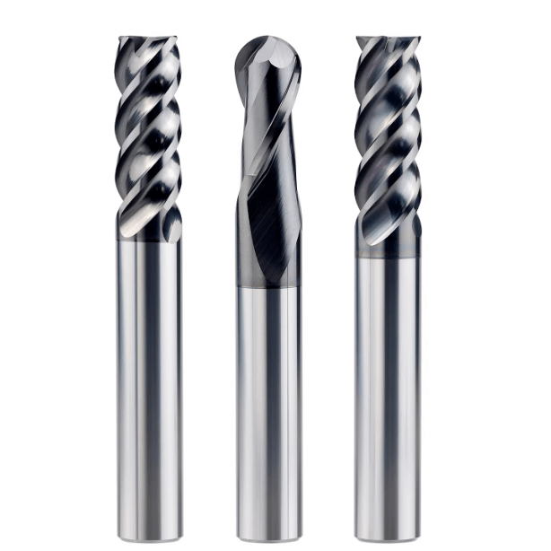
The bull nose structure refers to a tool design with a small-radius corner transition at the cutting tip. Compared to a flat end mill, a bull nose end mill features a fixed-radius arc at the junction of the cutting edge and the tool tip, which significantly reduces stress concentration and enhances resistance to chipping.
While it shares some geometry with flat end mills, the bull nose cutter is more efficient for bottom surface roughing and sidewall contour milling. In contrast, ball nose cutters excel at 3D surface machining but have a small contact area and limited bottom surface capability. Therefore, bullnose milling cutters are often used as semi-finishing tools, particularly in mold chamfering and multi-axis transitional area machining.
Common Sizes and Fillet Radius Parameters of Bull Mill Cutters
Bull end mill cutters come in flexible specifications, commonly ranging from Ø1mm to Ø20mm. The fillet radius (R) typically varies from R0.2mm to R2.0mm. Choosing the right radius depends on workpiece geometry and directly affects tool performance and residual material.
For small precision molds, such as electronic connector cavities, R0.2-R0.5mm fillets help preserve fine detail and extend tool life. For large mold bases and roughing tasks, R1.0-R2.0mm radii enhance cutting depth, stability, and shock resistance.
On 3-axis or 5-axis machines, fillet radius should also be selected based on simulation safety to avoid collisions during toolpath execution.
Naming Analysis: “Bull” Refers to Rounded Corners and Robust Tool Geometry
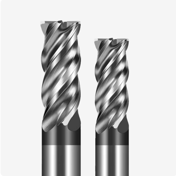
“Bull nose” literally means a bull’s nose and metaphorically describes the tool’s rounded geometry. The term refers to tools with a robust, rounded end—not a sharp angle or complete sphere. This form enhances impact resistance, chip flow, and strength during transition machining.
Because of this powerful, stable geometry, bull nose end mills are widely used in aerospace, automotive mold machining, die-casting mold applications, and other areas demanding high wear resistance and rigidity.

Main Functions and Advantages of Bullnose End Mill Cutters
How Rounded Corner Design Improves Strength and Anti-Chipping
The bull nose end mill’s rounded corner structure reduces stress concentration at the tool tip, a common failure point in traditional flat-bottom tools. The R-angle transition distributes cutting loads more smoothly, improving chipping resistance and fracture strength.
This feature also enhances wear distribution, making the tool ideal for high-hardness steels like H13 and SKD11. It’s especially suited for high-speed machining (HSM) and interrupted cutting, where tool stability is critical.
Ideal for Roughing and Semi-Finishing Operations
Bull nose cutters are well-suited for operations combining roughing and semi-finishing. Their ability to handle larger feeds and depths of cut while delivering smooth transitional surfaces makes them valuable in small to mid-size production runs.
On 3-axis and 4-axis machining centers, bull nose cutters excel at multi-tasking—cleaning bottom corners, roughing sidewalls, and contour milling. With the right toolpaths (like Z-level or constant-step strategies), they outperform traditional flat mills in semi-finishing and provide greater stability than ball nose tools.
Application Value in Mold Chamfering and Structural Components
Bull nose end mills are ideal for mold cavity chamfering, rib transition radii, and inner corner blending—areas where flat tools can’t reach and ball tools may leave excess material. Their fixed-radius design enables clean transitions and minimizes tool changes.
They’re also suitable for structural parts like automotive frames, aerospace components, and medical implants. These applications benefit from the tool’s ability to deliver consistent surface finish and support stress-distribution design principles.
Modern CAD/CAM software further enhances bull nose performance with automated R-radius recognition and optimized multi-axis toolpath generation.

Common Application Scenarios of Bull Nose Milling Cutters
Bottom Corner and Inner Wall Transitions in Mold Machining
In mold cavities—such as those for injection molding, die casting, or stamping—the transition areas at bottom corners are prone to tool breakage. Flat end mills leave sharp corners requiring separate cleanup, while bull nose cutters handle wall-bottom transitions in one pass, improving efficiency.
They’re ideal for rib roots, cavity sidewalls, and internal chamfering—enhancing structural strength while minimizing tool interference and secondary machining.
Performance on Carbide and Hardened Steels (HRC50+)
For materials like hardened steels (HRC55–65), SKD61, or tungsten carbide, bull nose cutters offer excellent chipping resistance and cutting stability. Their rounded corners disperse loads and reduce stress spikes.
Combined with PVD coatings and micro-grain carbide substrates, these tools maintain superior surface finishes even under high-speed or dry cutting conditions. Applications include die plates, precision cavities, and metal insert machining.
Programming should use constant cutting speeds and minimal step-downs to improve chip evacuation and maintain corner radius accuracy.
Comparison with Ball Nose Cutters: When to Use Which?
Ball nose cutters are ideal for complex 3D surfaces, thanks to their omnidirectional contact. However, they’re inefficient in bottom and sidewall milling.
Bull nose cutters bridge the gap—they maintain good surface finish while providing stronger edge engagement and better material removal rates. In multi-axis machining, they can be used for transitional zones before switching to ball tools for final surfacing.

How to Choose a Suitable Bull End Mill Cutter
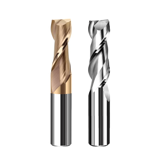
Tool Material and Coating Recommendations (TiAlN, PVD, etc.)
Tool substrate and coating largely determine performance. For mid-hard steels (P20, 718, 2311), TiAlN-coated micro-grain carbide offers oxidation resistance and high-speed capability.
For hardened steels (HRC55+), opt for coatings like AlTiN, TiSiN, or TiAlCrN to withstand high cutting temperatures. In aluminum, copper, and plastic mold machining, use uncoated or DLC/ZrN-coated tools to prevent built-up edges.
Cutting environment also matters—coating adhesion and thermal conductivity are essential for dry or MQL cutting.
How Fillet Radius Affects Machining and Tool Life
The fillet radius is critical for determining application fit, performance, and longevity:
- Small radii (R0.2–R0.5mm): Best for fine detail and low-load finishing.
- Medium radii (R0.75–R1.0mm): Most versatile—balance between roughing and semi-finishing.
- Large radii (R1.5mm+): High strength and shock resistance for deep or high-load cuts.
Radius size affects load distribution, thermal stress, wear, and vibration—select based on workpiece geometry and toolpath strategy.
Practical Selection Tips for Deep Cavities and Complex Contours
For deep cavities or multi-axis contours:
- Choose long-reach, corner-radius tools to reduce passes.
- Use high-helix (45°+) and polished flutes for chip evacuation.
- Reduced-neck tools improve sidewall clearance.
- Use constant engagement and helical ramping toolpaths for better stability.
In 5-axis machining, tool tilt strategies help reduce interference and dead zones—ideal for aerospace or medical parts.

How to Choose the Right Bull Nose End Mill Cutter
Tool Material and Coating Recommendations for Different Workpiece Materials
When selecting a bull nose end mill cutter, it’s critical to match the tool material and coating to the workpiece’s hardness, toughness, and thermal conductivity. A proper combination not only extends tool life but also enhances cutting efficiency and surface quality.
-
Hardened steels and heat-treated alloys (HRC 55+):
Use ultra-fine carbide tools with TiAlN, AlTiN, or TiSiN coatings. These coatings maintain hardness under high heat and resist wear, ideal for materials like SKD61 and 1.2344 mold steel during semi-finishing and finishing. -
Difficult-to-machine materials (e.g., stainless steel, titanium alloys):
Choose PVD coatings with high adhesion and oxidation resistance, such as TiAlCrN or CrN. These improve thermal conductivity and reduce built-up edge, improving stability during long tool engagement. -
Nonferrous metals (e.g., aluminum, copper):
Avoid high-temperature coatings. Instead, opt for uncoated tools with polished flutes or tools coated with ZrN or DLC, which minimize friction and prevent chip welding—ideal for high-gloss finishing.
Also consider the cooling method—for example, dry machining or MQL (minimum quantity lubrication)—when selecting the optimal coating for thermal control and chip evacuation.
How Fillet Radius Affects Machining Results and Tool Life
The corner radius on a bull nose end mill affects cutting load, edge strength, and surface finish. Selecting the correct radius is key to both performance and longevity:
-
Small radius (R0.2–R0.5mm):
Ideal for fine details and tight corners. Offers high precision with low cutting force, but has weaker tip strength—not suitable for heavy cuts. -
Medium radius (R0.75–R1.0mm):
A well-balanced option for shock resistance and form accuracy. Commonly used for mold cavities, chamfers, and 3D profile finishing. Works well with most CAM strategies. -
Large radius (R1.5mm+):
Excellent for high-load or roughing operations due to improved edge strength. However, it may leave uncut areas in fine detail zones.
Choosing the right fillet radius not only improves tool life but also helps reduce stress concentration on the workpiece, especially in hardened steels or during interrupted cuts.
Practical Selection Tips for Deep Cavities and Complex Contours
When machining deep pockets or 3D transitions, the cutter must ensure rigidity, clearance, and chip evacuation:
-
Tool length vs. rigidity:
For deep cavities, use reduced-neck or extended-length designs to maintain reach while minimizing vibration. -
Helix angle and flute finish:
Select high-helix tools with polished flutes to improve chip evacuation and reduce heat buildup—especially in tight cavities or blind pockets. -
Entry strategies:
Use tilted entry or spiral ramp-down paths to distribute cutting forces and maintain surface integrity. -
Avoid tool interference:
In 4- or 5-axis setups, choose necked-down bull nose cutters for better clearance in angled or undercut areas.
Pair these strategies with 3D adaptive toolpaths or constant-engagement CAM strategies to ensure consistent load and prolong tool life—especially for aerospace or mold applications.

Common Mistakes When Using Bull Nose Cutters—and How to Avoid Them
Using a Bull Nose Cutter for Finishing Tight R-Radii
Bull nose cutters have a fixed corner radius, making them unsuitable for forming sharp internal features (e.g., R0.1–R0.3mm). Using them in tight corners can cause:
-
Incomplete material removal in corners
-
Oversized corner radii, leading to dimensional inaccuracies
-
CAM toolpaths that don’t match tool geometry, leaving scallop marks
Solution: Use ball nose cutters or sharp-corner end mills for small-radius cleanup. Adjust CAM settings to assign precise tools for internal transitions.
Incorrect Feed Rates Causing Chatter or Tool Breakage
Despite their stronger tip, bull nose end mills still need carefully managed parameters. Common issues include:
-
Excessive feed rate, leading to sudden overload and tool breakage
-
Too deep side engagement, especially on vertical walls or deep cavities, causing vibration
-
Chatter marks or ripples on the surface
Recommendation: Follow the manufacturer’s cutting data. For semi-finishing, keep stepover (Ae) and feed per tooth (fz) conservative to avoid shock loads.
Poor Chip Evacuation Causing Tool Damage
Bull nose cutters are often used in semi-closed cavities and 3D contours, where chip evacuation is challenging:
-
Chips build up in the cavity, increasing local heat
-
Recirculating chips cause secondary cutting and faster wear
-
Sticky materials (e.g., stainless, titanium) cause edge chipping
Solution:
-
Use high-helix, polished-flute cutters
-
Apply air blast or mist cooling
-
In CAM, avoid dead-end cuts—add chip-breaking lifts or retract movements to prevent clogging