The lathe vibrates during the machining process, accompanied by the phenomenon of tool vibration and tool hitting. This causes chatter marks on the workpiece surface, and high rework and scrap rates. Where do we need to start with the investigation?
Workpieces and Cutting Tools
Workpieces
1. External turning of slender shafts. The distance between the general cutting point and the clamping point. If the aspect ratio exceeds 3, it is easy to vibrate the tool, so you can consider changing the process.
2 .External turning of thin-walled parts.
3 .Turning of box-shaped parts (such as sheet metal welding structural parts).
4. Cutting of superhard materials.
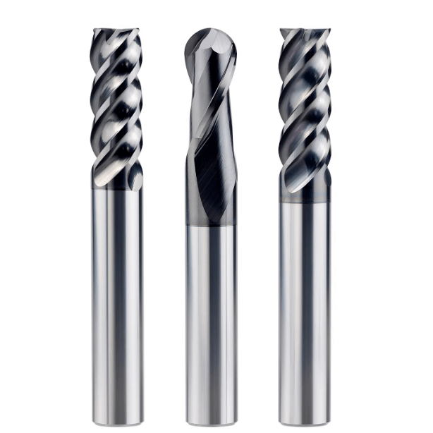
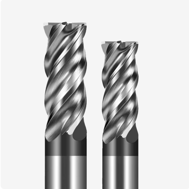
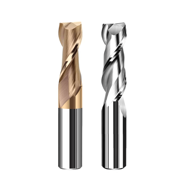
Cutting Tools
1. Use forming blades for forming turning.
2. The angle of the tool, especially the main rake angle, back angle and front angle, etc.
3. The sharpness of the blade.
4. Is the radius of the blade tip too large?
5. Are the cutting parameters appropriate?
First, eliminate the problem of the tool. Check the rigidity of the turning tool itself. Is it not clamped? Is it extended too long? Is the gasket uneven? Then check whether the turning tool (boring tool) is worn? Is the tip radius or the polishing edge too wide? Is the back angle of the turning tool too small? Check whether the current tool is 90 degrees or 45 degrees, and try to change it.
In addition, too small a tool feed (feed rate) may also be a cause of chattering. It can be slightly adjusted to increase it. Adjust the speed, single tool cutting depth, and feed rate to try to eliminate the resonance point.

Check the Reasons for the Machine Tool and the Clamping Position
1. Check if the live center is extended too long and the bearing is good. There is a plane rolling bearing combination inside. If you really doubt it, you can replace it with a dead center and pay attention to the lubrication of the center hole.
2. Check the clamping condition of the tailstock top. Under the clamping condition, are the left and right insides, the upper and lower insides not concentric with the machine tool spindle?
3. Tighten the large, medium and small slides, especially the middle slide.
4. If the tailstock part of the machine tool cannot be checked temporarily (points 1 and 2, some benchwork foundation is required), you can try to move the tool from the clamping end to the tail. On the contrary, the tail end can be removed to the greatest extent.
5. If there is still a problem in step 4, check the spindle. Of course, if it is a three-grip, check whether the spiral groove is damaged. The four-grip is manually self-adjusted, so there is no need to check.

Adopt Other Countermeasures to Suppress Tool Vibration
If your main bearing is really tight, and the workpiece is not a thin-walled hollow part or has a long overhang, there is no problem with the chuck clamping. Use other countermeasures to suppress the vibration of the tool.
There are some more specific and practical methods currently used in the processing site.
1. Reduce the working weight of the part that causes vibration. The smaller the inertia, the better.
2. Fix or clamp the place with the largest vibration, such as center frame, work holder, etc.
3. Improve the rigidity of the processing system. For example, use a tool holder with a higher elastic coefficient or use a special anti-vibration force with a dynamic damper to absorb impact energy.
4. Work hard on the blade and the direction of rotation of the workpiece.
5. Change the shape and angle of the tool. The smaller the radius of the tool nose, the better the reduction of cutting resistance. The side rake angle must be positive to make the cutting direction closer to vertical. The back rake angle is best to be positive, but the chip removal and chip cutting ability will be relatively poor. Therefore, a grooved tool can generally be selected to make the rake angle negative, but still maintain a positive cutting effect.