Micro end mills play a vital role in high-precision CNC machining, especially in industries like mold manufacturing, medical devices, microelectronics, and aerospace. These tools are designed to handle extremely fine structures and deliver high-resolution cutting results. However, to fully harness the capabilities of micro tools, selecting the right end mill size is critical.
Unlike standard end mill sizes, micro milling cutters have much smaller diameters and are designed for fine-detail machining. This puts higher demands on tool rigidity, machining parameters, and clamping systems. Even slight errors in size selection—especially when using metric end mills—can significantly impact surface finish and dimensional tolerance.
In applications involving deep cavities or high-aspect-ratio features, the choice of long-reach micro end mills and control over tool overhang become crucial. Poor tool-size matching can lead to chatter, deformation, tool breakage, and dimensional instability.

What Are Micro End Mill Cutters and Why Are They Ideal for Precision Machining?
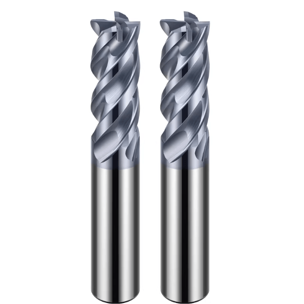
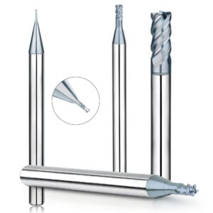
Micro end mills are specifically designed for fabricating precision components and intricate geometries. Typically ranging in diameter from 0.1 mm to 3 mm, they excel in creating microstructures and machining in confined areas. Their superior dimensional accuracy and cutting control make them indispensable in aerospace, medical, and precision mold applications.
Selecting the proper end mill size is key to achieving micromachining precision. Correct sizing directly affects cutting load, tool stability, and surface quality. Especially in CNC programs using metric end mills, accurate dimensional matching can dramatically increase the yield rate of precision parts.
Definition and Classification of Micro End Mills
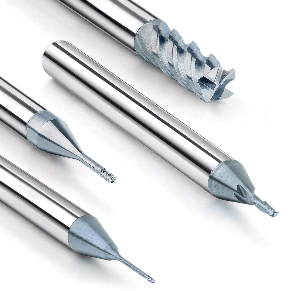
Micro milling cutters usually refer to end mills with a diameter less than 3mm. According to the number of blades, blade length, shank diameter and coating, they can be further subdivided into ultra-small diameter end mills, long-edge micro milling cutters, special-shaped blade micro milling cutters, etc. In terms of size system, they can be manufactured according to metric or imperial standards, and the specific size will follow the standard milling cutter size specifications of ISO or ANSI.
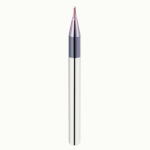
With the development of micromachining technology, micro tools with special coatings have also appeared on the market, such as CVD diamond coatings, which are used to process hard and brittle materials or high finish requirements. Different types of micro milling cutters have different usage strategies in tool selection and size matching, especially in small-size processing.
Key Application Areas: Mold Making, Medical Parts, and Microstructures
Micro end mills are used in fields requiring extremely tight tolerances and high surface finishes:
-
Mold Manufacturing: Micro tools clean up cavity corners and fine details after EDM operations, improving surface precision.
-
Medical Device Production: Extremely fine tools are used to shape stents, orthopedic implants, and microfluidic components.
-
Microstructure Fabrication: Applications like MEMS parts or micro-connectors often require tools smaller than 0.2 mm in diameter.
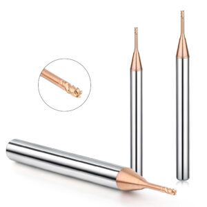
These scenarios often demand tools with high strength and form stability, often requiring long-reach micro end mills to reach deep or narrow areas without compromising accuracy.
Why Micro End Mill Size Selection Matters for Precision
Tool size directly affects machining accuracy, vibration control, and surface finish. Smaller tools offer greater detail but are more prone to vibration, breakage, and deflection. Engineers must carefully balance:
-
Tool diameter
-
Shank compatibility
-
Cutting depth and overhang
In deep cavity machining, higher length-to-diameter (L/D) ratios reduce rigidity. Thus, appropriate size selection becomes even more critical. Referring to standardized metric end mill charts during CNC programming helps control cutting paths and tolerance buildup.

Common Micro End Mill Sizes and Industry Standards
In precision CNC machining, micro end mills typically range from 0.05 mm to 3.0 mm in diameter, with some tools available in even smaller dimensions. These tools are essential for intricate tasks in electronics, medical components, and aerospace parts.
Tool size not only affects machining capabilities, but also determines the stability and life of the tool. When designing a process flow, it is crucial to choose the milling cutter size reasonably. Especially when facing deep cavity machining or narrow slit contours, it is necessary to combine long reach end mills for strategic size matching to avoid over-machining or tool breakage problems.
Micro vs Standard End Mill Sizes
Standard end mills follow international size standards (e.g., ISO, DIN, ANSI), usually ranging from 3 mm to 20 mm and up. They’re typically used for roughing and general contouring.
Micro end mills focus on ultra-precision, minimal feature size, and low cutting forces. They require tighter tolerance control—often ±0.005 mm or better—and differ in geometry, shank size, and overall length.
For ultra-hard materials like ceramics or silicon carbide, micro tools must exhibit high hardness and wear resistance to maintain dimensional accuracy.
Metric vs Imperial Micro End Mill Sizes
Micro milling cutters are available in both metric (e.g., 0.1 mm, 0.2 mm, 1.0 mm) and imperial sizes (e.g., 1/64″, 1/32″, 1/16″). Mixing unit systems can lead to size mismatches and affect CNC accuracy.
To avoid conversion-related errors, it’s best to standardize on one measurement system during process planning. In metric-dominant fields like precision mold making or microelectronics, use of metric end mills is preferred.
Common Mistakes in Micro Tool Size Selection
Even experienced engineers may fall into these common pitfalls:
-
Choosing the smallest diameter by default: Smaller isn’t always better. Ultra-small tools have lower rigidity and are prone to vibration and breakage.
-
Ignoring tool overhang ratio: Long-reach micro end mills must have sufficient shank support to avoid deflection and loss of precision.
-
Neglecting coating-material compatibility: For example, machining titanium alloys with uncoated tools can lead to rapid wear. Using ultrafine carbide or diamond-coated tools is more appropriate.
Best practice: Base your tool size on material properties, machining path, part wall thickness, and available standard sizes to ensure efficient, stable, and safe micro machining.

How to Choose the Right Micro Milling Cutter Size
In micro-machining, the reasonable selection of the size of the micro milling cutter not only affects the processing efficiency, but also directly determines the dimensional accuracy and surface quality of the finished product. Faced with different materials, different structural depths, and the limitations of the equipment spindle system, the tool size matching strategy needs to consider multiple factors comprehensively. The following will systematically analyze how to scientifically select the appropriate end mill sizes from three aspects: material properties, processing depth, and equipment adaptation.
Size Selection Based on Material Type
Each material demands a tailored cutting approach:
-
Copper and Aluminum (Soft Metals): Use sharp-edged tools with deep flutes and cutting diameters between 0.2 mm to 1.5 mm for high-speed and high-finish applications.
-
Titanium Alloys and Stainless Steel (Hard Metals): Due to the high hardness and low thermal conductivity of the material, it is recommended to use a micro milling cutter with a diameter of not less than 0.5mm, and use a carbide substrate or coated tool (such as AlTiN, TiSiN) to reduce tool wear.
-
Ceramics and Glass (Brittle Materials): Diamond-coated or PCD micro end mills, usually ≥ 0.3 mm in diameter, are preferred for chipping resistance and extended tool life.
Also consider cutting speed, feed rate, and cooling methods to maximize micro-tool effectiveness and reliability.

Size Selection Based on Machining Depth and Tool Overhang
When processing is required in deep cavities, narrow slits, complex internal angles and other areas, the tool overhang length and tool rigidity become key factors. At this time, long reach end mills are often needed to achieve structural avoidance.
However, as the tool length increases, its rigidity decreases rapidly. If the size is not selected properly, it is very easy to cause vibration, tool breakage, overcutting or surface accuracy reduction. The following are recommended matching principles:
- Cutting depth ≤ 2D (D is the tool diameter): micro end mills with regular shank length can be selected to ensure processing stability.
- Cutting depth ≥ 3D: It is recommended to use long reach end mills and use larger diameter tools to improve bending strength. For example, when processing deep grooves, a thin shank tool with a total length of Ø1.0mm × 12mm can be used.
- The processing performance of long tools can be further improved by using a vibration-damping tool holder (such as a heat shrink tool holder or a hydraulic tool holder).
Equipment Compatibility: Match Tool Size to Spindle and Holder Limits
In addition to the object being processed, the spindle system of the equipment itself also imposes certain restrictions on the selection of tool size. Especially in high-speed spindles or micro-machining centers, the tool holder diameter, clamping length, taper interface, etc. must be strictly matched.
- Spindle taper (BT30, HSK-E40, etc.): determines the range of tool holder diameters that can be used. Common micro tool holders are Ø4mm, Ø6mm, and Ø8mm. It is necessary to ensure that the tool holder matches the spindle chuck to avoid excessive runout due to loose clamping.
- Chuck system (ER11, ER16, heat shrink, etc.): Different chucks can clamp different minimum tool diameters. It is necessary to confirm that the tool holder diameter is consistent with the lower limit of the chuck. For example, ER11 can clamp a maximum of Ø7mm tool holders, but a precision reducer is required to clamp a Ø1mm micro tool.
- Tool total length limit: Some five-axis machines or high-speed spindle machine tools limit the total tool length to within 60mm, so it is necessary to consider the tool “effective processing length + safe clamping length” does not exceed this range when selecting.
Therefore, when selecting a micro end mill, it is recommended to simultaneously check the tool holder data sheet, spindle manual and chuck tolerance specifications to avoid selection errors or processing failures due to equipment limitations.
Stability and Size Strategy in Micro Milling
Due to the extremely small tool diameters involved, micro end mills are highly susceptible to vibration, thermal deformation, and chip evacuation issues during machining. Achieving high-precision results hinges on maintaining system stability. This is especially critical when machining superhard materials, complex microstructures, or deep cavities. In such cases, tool sizing, cooling methods, and toolpath strategies must be carefully engineered.
This article systematically explores how to improve micro milling stability from three key perspectives: rigidity control, cooling and chip evacuation, and machining parameters.
Does Smaller Tool Diameter Mean Poorer Rigidity? How to Control Chatter
In micro milling, a smaller tool diameter inevitably results in lower rigidity. Even minimal cutting forces can cause tool deflection or induce high-frequency chatter. Once chatter occurs, surface roughness deteriorates rapidly, and tool breakage becomes likely.
To suppress vibration in micro milling, consider the following strategies:
-
Minimize tool overhang: Reducing the tool extension length is fundamental to improving rigidity and minimizing deflection.
-
Use shallow cutting parameters: Apply conservative cutting strategies such as low axial depth (ap < 0.1D) and minimal radial engagement (ae < 0.05D) to enhance machining stability.
-
Adopt high-speed spindles: Increasing spindle speeds (e.g., 40,000–60,000 RPM) reduces chip load per tooth and improves surface finish by increasing cutting speed.
-
Select anti-vibration tool holders: Heat shrink holders and ceramic holders offer enhanced dynamic stiffness, which helps dampen vibration during high-speed cutting.
Cooling and Chip Removal Challenges at Micro Scale
Micro milling cutters feature ultra-fine geometries and delicate cutting edges. Conventional high-pressure coolant or flood cooling systems often fail to effectively reach the cutting zone and can even induce localized heating or “water hammer” damage to the tool edges. Therefore, customized cooling and chip evacuation approaches are essential.
Recommended methods include:
-
MQL or atomized air cooling: Use minimum quantity lubrication (MQL) or dry, high-velocity air streams to reduce heat without flooding the cutting zone. This helps prevent chip accumulation and tool damage.
-
Maintain efficient chip evacuation: With only 2–3 flutes and minimal chip space, micro tools are prone to chip packing. Consider reverse toolpaths or layered roughing strategies to facilitate effective chip removal.
-
Use coated tools: Coatings like DLC (Diamond-Like Carbon) and TiAlN enhance wear resistance, reduce friction, and improve heat dissipation—indirectly supporting better chip evacuation and tool life.
Toolpath Design and Cutting Parameters for Micro Milling
Toolpath strategies and parameter selection in micro milling must diverge from traditional roughing approaches. Instead, focus on “high-frequency light cutting” with optimized tool engagement to achieve both precision and efficiency.
Key suggestions include:
-
Use constant load paths: Toolpaths that maintain consistent engagement, such as constant-stepover or constant-Z strategies, reduce the risk of localized tool overload.
-
Optimize feed per tooth and depth-width ratios: In most micro milling operations, maintain fz between 0.001–0.005 mm/tooth. The ae/ap ratio should ideally remain ≤ 1 for better balance and control.
-
Adopt multi-step roughing and finishing: Begin with mid-size micro tools for roughing, then switch to smaller tools for finishing or corner cleanup to extend tool life and improve accuracy.
-
Select low helix or variable pitch geometries: Tools with low helix angles or unequal flute spacing reduce cutting vibration and enhance surface finish consistency.

Recommended Micro Milling Cutter Size Ranges and Selection Tips
In precision CNC machining, selecting the correct micro end mill size is critical—not just for efficiency but also for achieving desired dimensional accuracy, surface finish, and tool longevity. Given the tight tolerance range and limited processing margin of micro tools, engineers should develop a size selection strategy based on part geometry, machine capability, and material type.
Suggested Size Ranges Based on Machining Accuracy
Tool diameter selection should closely align with the required machining tolerance. In applications such as microchannels, high-precision molds, or tiny part features, the tool diameter must be precisely matched to the geometry.
Recommended size ranges:
-
0.1 mm – 0.3 mm: Ideal for microchannels and micro-electronic features. Requires ultra-high-speed spindles (≥ 50,000 RPM).
-
0.4 mm – 0.6 mm: Suitable for cleanup of internal corners and fine features in precision parts. Balances rigidity with precision.
-
0.8 mm – 1.0 mm: Versatile size range for general micro machining, such as medical components and small cavity work that requires both roughing and finishing.
Always consider tool tolerance and actual cutting diameter in toolpath planning to avoid deviations in finished dimensions.
Quick Reference Table: Micro End Mill Sizes by Application
| Machining Application | Recommended Tool Diameter | Tool Type | Special Recommendations |
|---|---|---|---|
| Microchannels / Microstructures | 0.1mm ~ 0.3mm | 2-Flute Corner Radius End Mill | Use coated tools with high-speed spindles |
| Medical Implant Grooves | 0.4mm ~ 0.6mm | 2- or 3-Flute End Mill | Choose long-reach tools and control chatter |
| Precision Mold Corner Cleanup | 0.5mm ~ 0.8mm | Ball Nose or Corner Radius End Mill | Ensure proper path overlap to avoid overcutting |
| Slotting in Hard-Brittle Materials | 0.6mm ~ 1.0mm | Diamond-Coated Tool | Prefer dry cutting with minimum lubrication |
Summary Tips: Balancing Practicality and Precision
In practice, smaller tool diameters improve feature resolution but reduce rigidity and lifespan. Engineers should aim to use the largest tool diameter that still meets part tolerance, improving system stability and throughput.
Practical guidelines:
-
Start with larger tools during testing: Then progressively downsize if necessary, reducing tool wear and setup risk in early stages.
-
Match tool shank diameter with spindle interface: Ensures proper clamping and avoids interference or vibration from unstable tool holding.
-
Monitor cutting depth-to-width (ap/ae) and L/D ratios: Keep tool deflection under control during machining, especially in deep or narrow geometries.
-
Use long-neck or extended-reach tools strategically: For deep cavities or constrained spaces, ensure adequate clearance while maintaining tool rigidity.
Unlocking the Full Potential of Micro Milling Cutters
Proper micro end mill sizing is a cornerstone of successful high-precision machining. This article examined the core role of size strategy in micro milling, explored tool rigidity, cooling, chip removal, and machining parameters, and offered sizing recommendations based on accuracy requirements and application scenarios.
Engineers must take a holistic approach to tool selection—factoring in material characteristics, depth of cut, tool overhang, and spindle capabilities. For difficult-to-machine materials like copper alloys, titanium alloys, or ceramics, proper tool diameter selection is essential for optimizing performance.
By understanding the core principles of tool sizing and applying them systematically, CNC engineers can fully harness the advantages of micro milling and achieve a balance between precision and productivity.