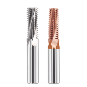
In high-precision thread milling, the 60-degree thread cutting mill tool plays a critical role in achieving high-quality thread surfaces and stable machining. Proper optimization of feed rate and spindle speed directly affects thread accuracy, surface finish, tool life, and overall machining efficiency. By carefully setting the cutting parameters of a CNC thread milling tool, common issues such as tool vibration and chipping can be minimized, improving process stability.
Different materials significantly affect the rigidity and wear resistance of solid thread milling tools during cutting. For instance, aluminum alloys allow higher spindle speeds to increase cutting efficiency, while stainless steel or titanium alloys require reduced feed rates and multiple cutting passes to maintain thread quality. Thread depth, pitch, and tool overhang also directly influence parameter selection.
Selecting appropriate guidance from a reputable thread milling tool manufacturer is essential for optimizing parameters. By combining manufacturer-recommended cutting speeds and feed rates with the machine’s rigidity characteristics, operators can quickly adjust the 60-degree thread cutting mill tool’s process plan to achieve high efficiency, precision, and stability.

Parameter Optimization Logic for 60 Degree Thread Cutting Mill Tools in CNC Machining
When using 60-degree thread cutting milling cutters, proper parameter settings are essential for achieving accurate and smooth threads. Adjusting cutting speed, feed rate, and the number of cutting passes can reduce tool wear and vibration, while maintaining thread profile stability. By considering material hardness, thread depth, and machine rigidity, operators can develop effective machining strategies that improve the efficiency and lifespan of solid thread milling tools.
In mass production or multi-specification machining, parameter optimization affects both efficiency and consistency. When using a CNC thread milling tool, carefully calculating feed rate and spindle speed balances cutting force and tool load. Correct parameter logic reduces rework rates and ensures repeatable, high-precision thread production.
The Impact of 60° Thread Angle on Feed Rate and Spindle Speed Calculations
The 60° thread angle influences cutting force distribution and tool load. In thread milling, the contact length between the cutting edge and the workpiece surface varies with the thread angle, which affects feed rate and spindle speed selection. Larger thread angles increase peak cutting forces, requiring a lower feed rate and properly matched spindle speed to ensure smooth cutting, minimize vibration, and reduce tool wear.
Thread angle also affects chip evacuation and surface finish. When machining high-hardness stainless steel, for example, the rigidity and geometry of solid thread milling tools must be considered to optimize feed and speed, ensuring thread accuracy and surface quality. This approach helps extend tool life and improve process stability.
The Relationship Between Pitch, Thread Depth, and Thread Mill Tool Cutting Load
Pitch and thread depth are critical factors affecting tool load. Smaller pitches and deeper threads increase cutting forces, placing higher loads on the thread mill tool, which requires adjustments to feed rate and cutting passes. Layered cutting or modifying cutter geometry can reduce unit cutting forces, ensuring smooth thread formation and accuracy.
Material type and tool material also influence cutting load. For hardened steel or high-temperature alloys, the CNC thread milling tool’s rigidity and life data must be considered to reduce feed rate or increase cutting passes. This ensures reliable thread machining while maintaining production efficiency.
The Impact of CNC Thread Milling Tool Helical Interpolation Method on Cutting Stability
Helical interpolation is a core technique in thread milling, with path planning directly affecting cutting stability and thread accuracy. Optimizing the helical interpolation method balances cutting forces, reduces tool vibration, and enhances stability of the 60-degree thread cutting mill tool during high-speed operations. Proper interpolation allows full use of the rigidity of solid thread milling tools while reducing heat buildup and tool wear.
In complex or deep-hole threads, the interpolation strategy must consider tool diameter, thread depth, and material hardness. Adjusting feed steps and helix angles for different pitches and depths prevents uneven tool load and discontinuous cutting, ensuring surface finish and repeatability.

Feed and Speed Strategies for 60-Degree Thread Cutting Mill Tools in Different Materials
Cutting performance varies across materials, making proper feed and speed settings critical. Aluminum alloys allow higher cutting speeds, leveraging the efficiency of 60-degree thread cutting mill tools in high-speed milling. Harder materials such as stainless steel and titanium alloys require lower feed rates and multiple passes to maintain stability and surface quality. Tailored processing strategies extend the life of solid thread milling tools and reduce vibration or chipping risk.
Thread depth, tool diameter, and machine rigidity also influence optimal parameters. In multi-batch or multi-variant production, combining manufacturer-provided cutting data with machine tool specifications enables quick, stable, and efficient thread milling. Systematic parameter adjustments ensure consistent thread accuracy and surface quality across materials.
Key Points for High-Speed Application of Thread Mill Tools in Aluminum Alloy Machining
Aluminum alloys have low cutting force, good thermal conductivity, and are prone to chip adhesion. Higher spindle speeds with optimized feed rates enable efficient, high-speed thread milling. Rigid solid thread milling tools should be used along with optimized cutting depth and tool geometry to prevent vibration or chip sticking.
Chip evacuation and surface quality at high speed also require attention. Optimizing coolant flow, tool coating, and helical interpolation maintains thread stability, enhancing efficiency and accuracy. This is particularly important in small-batch, multi-variant production to ensure consistent quality.
Feed Control Principles for CNC Thread Milling Tools in Stainless Steel Machining
Stainless steel has high strength and low thermal conductivity, causing heat buildup and rapid tool wear. Feed rate must be carefully controlled, cutting depth minimized, and layered cutting employed to keep cutting forces within tool limits.
Spindle speed should match tool rigidity and machine performance to prevent vibration and discontinuous cutting. Optimizing feed and speed improves surface finish and dimensional accuracy while extending the life of solid thread milling tools.
Parameter Requirements for Solid Thread Milling Tools in Titanium Alloy and High-Temperature Alloy Machining
Titanium and high-temperature alloys are hard and thermally challenging. Cutting speed must be low, feed rate reduced, and multiple passes used to reduce tool load. Tool rigidity, coating, and geometry are critical for stability and thread accuracy.
Properly designed cutting passes and helical interpolation reduce heat buildup and vibration. Manufacturer-recommended parameters help optimize efficiency, accuracy, and surface finish, achieving reliable high-performance machining.
Stable Cutting Parameter Settings for Cast Iron and Hardened Steel Thread Milling
Cast iron is brittle and prone to chipping, while hardened steel requires high cutting forces. Optimizing feed rate, cutting depth, and number of passes maintains tool stability and thread integrity. Layered cutting and proper interpolation control force peaks and reduce vibration.
For hardened steel, combining tool geometry and coating with adjusted feed rates ensures accuracy and surface finish. Scientific parameter settings enable high-rigidity, high-precision thread milling suitable for mass production and high-precision applications.

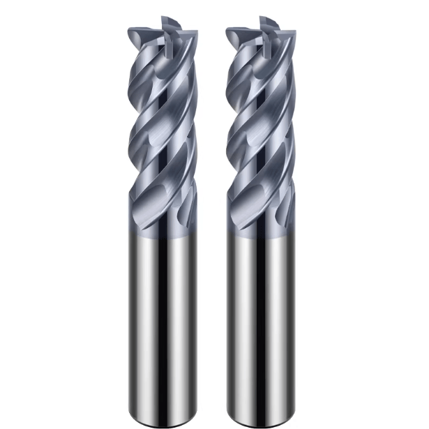
The Impact of Solid Thread Milling Tools on Feed Rate and Spindle Speed Windows
The rigidity and wear resistance of solid thread milling tools directly determine the permissible feed rate and spindle speed during machining. High-rigidity solid carbide thread milling cutters can withstand greater cutting loads. This allows for high-speed, efficient thread milling while maintaining thread profile stability. Properly matching tool geometry, thread depth, and material hardness maximizes tool performance, reduces vibration, and minimizes tool wear.
Different materials and thread specifications impose different requirements on the cutting window of solid thread milling tools. By combining technical data from the thread milling tool manufacturer with machine tool performance, operators can set feed rate and spindle speed to achieve repeatable, high-precision machining. This strategy applies to single-piece machining as well as mass production and small-batch, multi-variant operations.
The Support Capacity of Solid Carbide Thread Milling Cutter Rigidity on Feed Rate
Solid carbide thread milling cutters provide exceptional rigidity and bending resistance, allowing stable cutting even at high feed rates. High-rigidity tools withstand larger cutting force peaks, reduce vibrations, and improve thread machining accuracy. In deep hole or hard material machining, the rigidity advantage of solid thread milling tools is particularly evident, enabling stable layered cutting and continuous helical interpolation.
Additionally, rigid tools support high-speed operations. In small-hole internal threads or high-pitch threads, combining appropriate cutting parameters fully utilizes the efficiency potential of the 60-degree thread cutting mill tool. This reduces rework and tool wear, ensuring high-quality, stable thread machining.
Matching the Number of Tool Flutes with the Spindle Speed of the 60-Degree Thread Cutting Mill Tool
The number of tool flutes affects spindle speed, cutting force distribution, and heat accumulation. A 60-degree thread cutting mill tool with more flutes distributes cutting loads evenly during high-speed milling, reducing thickness per tooth and improving surface finish and tool life. Conversely, tools with fewer flutes are prone to vibration at high speeds, requiring reduced feed or spindle speed to maintain stability.
Feed rate and spindle speed should be adjusted based on thread depth, pitch, and workpiece material, in combination with the number of tool flutes. Proper matching enables high-efficiency machining while ensuring thread accuracy, making this approach ideal for small-batch, multi-variant, and high-precision production.
Limitations of Tool Overhang Length on Thread Mill Tool Cutting Parameters
Tool overhang length significantly affects machining stability. Excessive overhang reduces rigidity, increasing vibration and force fluctuations, which negatively impact thread accuracy and surface quality. Operators should minimize overhang based on thread depth and hole diameter while adjusting feed and spindle speed to keep cutting forces within the tool’s capacity.
A reasonable overhang length, combined with layered cutting and helical interpolation, reduces heat buildup and tool wear. By accounting for the material and geometry of solid thread milling tools, operators can achieve high-precision, repeatable thread machining without sacrificing efficiency. This is especially important for small holes, deep holes, and hard materials.

Differences in Feed Rate and Spindle Speed in Internal and External Thread Machining
Feed rate and spindle speed selection differs between internal and external threads due to cutting space and tool force constraints. Internal threads have limited space, reducing tool rigidity and increasing vibration and thread profile deviations. Conservative parameters are usually adopted to maintain stability. External threads offer more space and rigidity, allowing higher feed rates and efficient machining. Combining solid thread milling tool characteristics optimizes cutting strategies, improving thread accuracy and surface quality.
Thread depth, hole diameter, and material hardness also affect parameter choice. By analyzing cutting forces and tool wear, operators can develop a scientific combination of feed and speed to ensure consistent machining in both mass production and small-batch, multi-variant operations. Differentiated parameter optimization balances efficiency and tool life.
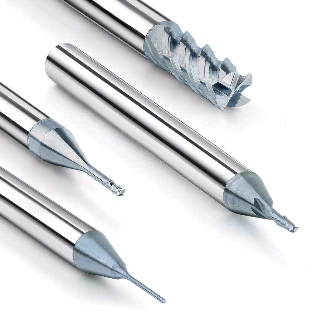
Conservative Parameter Strategy for CNC Thread Milling Tools in Small Hole Internal Thread Machining
Limited tool rigidity and cutting space require reduced feed rates and cutting depths to prevent vibration and chipping. Layered cutting and helical interpolation evenly distribute cutting load, ensuring thread profile accuracy and surface quality.
Tool material and coating enhance stability. Solid thread milling tools provide higher rigidity and wear resistance, enabling stable cutting even at lower spindle speeds. Conservative parameter strategies extend tool life and improve processing consistency.
The Impact of Layered Cutting on Feed Rate in Deep Thread Machining
Excessive single-pass cutting in deep threads increases cutting forces, tool vibration, and thread deviation. Layered cutting splits thread depth into multiple passes with smaller per-pass cutting volumes, reducing tool load and ensuring profile accuracy.
Layered cutting also improves chip evacuation, reduces heat buildup, and enhances surface finish. Combined with manufacturer recommendations and machine rigidity, feed rate and spindle speed can be adjusted per pass for high-precision, stable deep thread machining.
Efficiency-Oriented Parameter Settings for Thread Mill Tools in External Thread Milling
External threads allow efficiency-oriented feed and speed settings due to ample space and higher tool rigidity. Increasing spindle speed and feed rate improves machining efficiency while maintaining thread accuracy, suitable for mass production or multi-variant operations.
Parameters should be optimized based on pitch, thread depth, and material. Solid thread milling tools enhance tool stability and lifespan, enabling efficient settings while ensuring quality and reducing tool wear and rework.

Common Feed and Speed Problems and Their Impact on Thread Quality
Improper feed and speed are major factors affecting thread accuracy and surface quality. Excessive feed or insufficient spindle speed can cause uneven cutting forces, vibration, increased tool wear, or profile deviations. Adjusting parameters scientifically with consideration of solid thread milling tool rigidity and geometry improves stability and surface finish.
In mass production or small-batch, multi-variant machining, incorrect parameter combinations reduce consistency, increasing rework and tool replacement. Following manufacturer-recommended parameters and combining them with machine rigidity and tool geometry can effectively avoid common feed and speed problems, ensuring high-efficiency, high-precision thread milling.
Thread Profile Distortion Caused by Excessive Feed Rate
Excessive feed increases cutting load, causing vibration and tool deformation, leading to profile distortion or tooth deviation. This is especially critical in small-hole internal or deep threads. Using layered cutting with a 60-degree thread cutting mill tool reduces peak forces, ensuring thread profile accuracy and consistency.
High feed rates also accelerate tool wear and chipping, particularly in hard materials. Combining solid thread milling tool rigidity and coatings extends tool life and reduces rework while maintaining surface quality.
Discontinuous Cutting and Surface Roughness Caused by Insufficient Spindle Speed
Low spindle speed causes discontinuous cutting, poor chip evacuation, and surface roughness or chatter. In hard materials, low speed concentrates heat, accelerating tool wear and affecting accuracy. Increasing spindle speed appropriately, combined with proper feed, maintains continuous cutting and smooth, accurate threads.
Optimizing spindle speed with tool rigidity and machine performance reduces vibration and discontinuous cutting risks, improving repeatability and surface finish while maintaining efficiency.
The Impact of Parameter Mismatch on Solid Thread Milling Tool Life
Mismatched parameters can overload or locally chip solid thread milling tools, shortening life. Excessive feed or low speed increases cutting force peaks, causing tool wear and higher replacement costs. Matching thread depth, pitch, material hardness, and tool geometry extends tool life.
Mismatched parameters also degrade surface quality and consistency, increasing rework. Using thread milling tool manufacturer data and machine performance to set feed and spindle speed maximizes solid thread milling tool rigidity and wear resistance, achieving precise, efficient, and long-lasting thread milling.
Parameter Optimization Method Based on Practical Machining Experience
In thread milling practice, accumulated machining experience can significantly improve efficiency and thread quality. A rational parameter optimization method depends not only on theoretical calculations. It also considers machine tool performance, material characteristics, and the rigidity and wear resistance of solid thread milling tools. By verifying cutting speed, feed rate, and the number of cutting passes through actual operation, potential issues can be quickly identified, allowing operators to adjust tool paths and machining strategies for high-precision results across different thread specifications and materials.
Furthermore, the optimization method should address both mass production and small-batch, multi-variant production. By combining recommended data from the thread milling tool manufacturer with the machine tool’s own conditions, operators can develop standardized machining plans to ensure consistent thread profiles and surface finish. This systematic approach extends tool life, reduces rework, and improves overall production efficiency.
How to Rapidly Optimize 60-Degree Thread Cutting Mill Tool Parameters Through Trial Cutting
Trial cutting is an essential method to quickly verify the suitability of cutting parameters. By performing short-distance cuts, operators can observe thread surface quality, tool load, and vibration to determine whether the feed rate and spindle speed are appropriate. For different materials or thread specifications, trial cutting promptly identifies issues such as excessive cutting force, tool wear, or thread profile deviations, providing a reliable basis for parameter adjustment.
During trial cutting, combining the number of cutting edges, geometric angles, and coating characteristics of solid thread milling tools allows rapid optimization of feed rate and cutting passes. This ensures accuracy and stability in thread machining. Meanwhile, trial cutting helps verify the feasibility of the 60-degree thread cutting mill tool in small-hole or deep-hole operations, providing reliable data for production.
Optimizing CNC Thread Milling Tool Feed Rate Using Machine Tool Rigidity and Spindle Performance
Machine tool rigidity and spindle performance directly influence cutting stability and vibration during thread milling. On high-rigidity machines, feed rate and spindle speed can be increased to improve efficiency, while on lower-rigidity machines, feed rate should be reduced to maintain stability. By leveraging machine tool performance, the advantages of solid thread milling tools are fully utilized, minimizing the impact of tool wear and vibration on thread accuracy.
Optimizing cutting parameters together with spindle power and speed range ensures cutting forces remain within the tool’s capacity, preventing overload and chipping. Matching machine tool performance with tool characteristics is crucial for improving thread machining efficiency and surface quality, and provides stable support for mass production.
Techniques for Maintaining Thread Mill Tool Parameter Consistency in Mass Production
Consistency in thread milling parameters is critical for both accuracy and efficiency. Establishing standardized machining parameter tables, combined with the performance and lifespan data of the 60-degree thread cutting mill tool, ensures each workpiece is machined within the same feed rate and speed range, reducing dimensional deviations and surface defects.
Regularly checking machine tool condition, tool wear, and cutting fluid supply prevents quality fluctuations caused by parameter deviations. In small-batch, multi-variant production, planning tool paths and cutting passes in conjunction with manufacturer guidance achieves high consistency and stability while extending tool life and improving overall efficiency.

The Significance of Parameter Recommendations from the Thread Milling Tool Manufacturer’s Perspective
Manufacturer-recommended parameters provide not only theoretical cutting speeds and feed rates but also practical guidance based on tool material, number of flutes, geometric design, and coating performance. Referring to these data allows operators to develop machining plans for different materials, thread specifications, and machine conditions. This prevents tool overload, vibration, or thread profile distortion caused by blind parameter selection. Properly matching feed rate and spindle speed with the 60-degree thread cutting mill tool maximizes the rigidity and wear resistance of solid thread milling tools, enhancing machining stability and efficiency.
In mass production, small-hole or deep-hole machining, or multi-specification operations, following thread milling tool manufacturer recommendations reduces deviations and rework. By adjusting parameters according to machine tool performance, thread depth, pitch, and tool overhang, highly repeatable and precise thread machining can be achieved. Recommended parameters provide both theoretical guidance and practical support for efficient, stable, and reliable thread milling.
Matching Principles Between Tool Manufacturer’s Recommended Parameters and Actual Machining Conditions
Manufacturer parameters are usually based on standard materials and ideal machine tool conditions. In practice, adjustments must be made based on workpiece material, machine rigidity, spindle performance, and thread depth. For example, in stainless steel or high-temperature alloys, even if the manufacturer recommends a higher feed rate, cutting speed should be reduced to prevent tool chipping or surface roughness. Matching theoretical parameters with actual conditions ensures stable thread profiles and surface finish.
Operators should monitor tool wear and heat accumulation and adjust feed rate and spindle speed as necessary to maintain optimal tool performance. This approach extends solid thread milling tool life, improves production efficiency, and reduces rework.
Differences in Parameter Design Among Different Thread Milling Tool Manufacturers
Tool materials, coatings, number of flutes, and geometric angles vary between manufacturers. Even for 60-degree thread cutting mill tools of the same specifications, recommended feed rates and spindle speeds may differ. Understanding these differences helps operators select the most suitable tools and parameters for their machine and materials.
Manufacturers typically balance tool life, cutting stability, and processing efficiency when designing parameters. For instance, solid carbide cutters may excel on hard materials, while high-speed steel tools are more efficient on lightweight alloys. Comparing manufacturer parameter designs allows operators to optimize machining strategies for maximum stability and efficiency.
How to Adjust Feed Rate and Spindle Speed to Suit Your Machine Tool Based on Manufacturer Data
Manufacturer-recommended parameters should be adjusted according to machine rigidity, spindle power, tool overhang, and thread depth. For internal threads in small or deep holes, feed rate and spindle speed should be reduced, using layered cutting to maintain stability and surface finish. For external threads or large diameters, feed rate and spindle speed can be increased if tool stability is ensured.
Combining tool geometry, coating, and number of cutting edges allows rapid parameter adjustment based on manufacturer data. This ensures thread accuracy, machining stability, extended tool life, and reliable mass production consistency.