In modern manufacturing, 3D surface machining has become a core process in high-end fields such as molds, aviation, and medical treatment. In order to cope with these complex contours and high-precision surface requirements, ball nose end mills have become an essential tool for precision machining and high-quality surface treatment due to their unique structure and cutting characteristics. This article will systematically analyze the key value of ball nose milling cutters in 3D surface machining from tool structure, performance advantages, common problems to optimization strategies. Help engineers find a balance between improving efficiency, maintaining quality and controlling costs.

Why Does 3D Surface Machining Require “Ball Nose Milling Cutters”?
With the increasing requirements of manufacturing for part complexity and surface accuracy, 3D surface machining has become one of the core processes in high-end fields such as mold manufacturing, aerospace, and medical devices. Whether it is the precision shaping of freeform surfaces or the finish control of mold cavities, higher requirements are placed on tool performance and toolpath strategy.
In this context, ball nose end mill bit has become the preferred tool in 3D surface machining due to its unique structure and cutting characteristics. Compared with flat milling cutters, ball nose milling cutters can better fit complex contours and significantly improve surface finish and surface consistency when performing Z-level finishing or constant scallop machining.
However, many processing companies still face many pain points in actual operations:
- The tool marks are obvious, the accuracy fluctuates greatly, and it is difficult to meet the mirror-level requirements.
- The processing efficiency is low, especially when the time cost is too high for large-area finishing.
- The tool wears quickly and is easy to break, resulting in poor processing stability.

In 3D surface processing, the matching degree between tool geometry and application directly determines the quality of the finished product and processing efficiency. If a ball-end milling cutter that is not suitable for the current working conditions is used, it often brings a series of hidden problems. For example:
- Cutting interference and path overcutting: The wrong tool tip radius or blade length configuration is easy to cause interference on complex surfaces or inside cavities. It leads to local overcutting and destroys the designed surface contour.
- Abnormal surface roughness: When using non-finishing tools for detail processing, it is often due to insufficient tool rigidity or abnormal contact angle. The residual texture is coarse and the ripples are obvious, and the Ra value cannot meet the standard.
- Geometric error accumulation: If the tool runout control is poor or the actual blade shape deviates from the design requirements. Errors may be superimposed layer by layer in multi-axis interpolation or spiral paths, resulting in overall contour distortion.
- Tool life is drastically shortened: Unreasonable ball end tool application will concentrate the cutting force on the tool tip, resulting in heat accumulation and micro cracks. In severe cases, it may even cause accidents such as chipping and tool breakage, which will affect the continuity of processing.
The root cause of these problems is often not the equipment itself. Instead, it lies in factors such as a lack of understanding of the characteristics of ball end tools, improper path strategies, and unreasonable parameter configuration. Only by mastering the correct ball end milling cutter application strategy can its potential in 3D profiling and high-precision surface processing be truly released.
This article will systematically analyze the application advantages of ball end milling cutters in 3D surface processing. And combined with practical experience, it provides a set of operational optimization ideas and tips. Help you improve efficiency, improve precision, and extend tool life in actual processing.

What is Ball Nose End Mill?
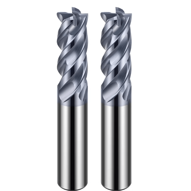
A ball end mill is a spherical tip end mill designed for machining complex surfaces, bevels, cavities and mold cavities. Its unique tip geometry allows for continuous contact during three-dimensional surface machining. It effectively reduces contour errors and step-shaped machining marks, and plays a key role in mold machining, five-axis machining and high-precision surface treatment.
Basic Structural Features
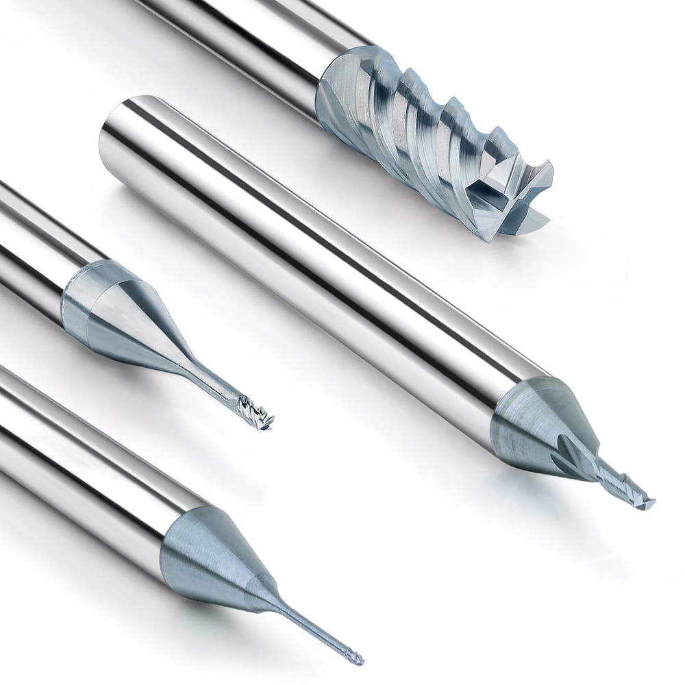
The tip of a ball end mill is hemispherical, which enables multi-axis interpolation at different angles and directions, making it an ideal tool for processing free curves and inclined surfaces. Depending on the application requirements, ball end mills can be designed with different numbers of blades. For example, 2 blades are suitable for rough machining with higher chip removal capabilities, while 4 blades are more suitable for finishing that requires high surface quality.
In addition, some variants such as fillet milling cutters, although similar in appearance, do not have the advantages of full ball end cutting and are often used in transition areas or semi-finishing operations.

Common Materials and Coatings
High-performance ball end mills are usually made of ultra-fine carbide to ensure wear resistance and chipping resistance in high-intensity cutting. Depending on the different processing materials (such as hardened steel, titanium alloy, stainless steel, etc.), different coating technologies are often used on the tool surface:
- AlTiN (aluminum titanium nitrogen): suitable for high-temperature dry cutting, strong wear resistance.
- TiSiN (titanium silicon nitrogen): the first choice for high-hardness materials, with outstanding anti-oxidation ability.
- DLC (diamond-like carbon coating): used for low-friction processing of aluminum alloys, graphite, etc.
These coatings not only improve the tool life, but also improve the thermal stability and surface treatment capabilities in high-speed machining.
Application Differences with Flat End Mill
Compared with flat end mills, ball nose mills perform better in processing complex three-dimensional contours, especially suitable for surface finishing, chamfering, and inner cavity curvature transition. Flat end mills are more suitable for 2D contour processing, step surface, plane roughing and other scenarios.
A key difference is that the ball nose tool contact point is point contact, the processing path is softer but the feed is limited; while the flat end mill is line contact, suitable for large cutting depth and high metal removal rate operations.

5 Advantages of Ball Nose End Mill in 3D Surface Processing
In 3D contour processing, ball-end milling cutters show significant advantages with their unique tip shape and continuous contact capabilities. The following five characteristics are its irreplaceable key value in modern CNC machining, especially in the manufacturing of complex molds and free-form surface parts.
Realize Complex Contour and Freeform Surface Machining
The spherical cutting edge of the ball-end mill can smoothly fit complex geometry and easily cope with structures such as surface gradients, double curvatures, bevels and grooves. This ability makes it the tool of choice for surface modeling, 3D engraving, blade and mold cavity manufacturing.
Its point contact cutting mechanism reduces cutting interference and gives the tool higher geometric flexibility in path adjustment.
High Surface Finish & Integrity
Because the cutting point is located at the center of the sphere, the ball-end milling cutter can maintain a very small residual height during small step finishing, thereby obtaining a smoother surface texture.
Especially in scenarios with high surface requirements such as precision molds, medical implants, and aerospace structural parts, the ball nose end mill can effectively control surface integrity and reduce secondary polishing and post-processing costs.

Support Multiple Path Strategies
Ball nose milling cutters are particularly suitable for contour processing, equidistant paths, and inclined cutting under five-axis linkage. These path forms help optimize the tool contact angle and achieve a more stable cutting load.
Its structural characteristics also make it suitable for automatic tool path generation systems and highly compatible with mainstream path optimization algorithms.
Reduced Tool Change & Workflow Stability
In scenarios where roughing and finishing transitions are required, ball nose cutters with large blade length or variable blade diameter design can complete multiple processes in one clamping, significantly reducing the number of tool changes, improving processing continuity and machine tool utilization.
Especially in areas such as mold inserts, deep cavity contours, and concave spaces, using a single ball cutter can avoid tool change errors and tool misalignment problems.
Suitable for Five-axis Linkage, Optimized for Multi-Axis Machining
In a five-axis machining environment, the ball nose cutter can approach the workpiece at any angle due to its non-directional spherical end, achieving cutting edge angle adjustment, interference avoidance, and high-precision surface fusion.
For example, when processing deep grooves, oblique holes, and chamfer transition areas, the ball nose milling cutter can smoothly transition without interrupting the machining path, and is a core tool in the machining of complex aviation parts and automotive mold surfaces.
The ball nose end mill shows extremely high adaptability in dealing with complex surfaces, high-quality surfaces, flexible path strategies, and multi-axis control. It is an indispensable tool type in modern precision manufacturing. Mastering its performance advantages and reasonably using the corresponding tool path strategies and parameter settings will greatly improve your 3D machining efficiency and quality.

Troubleshooting & Common Mistakes
Even with the use of high-quality ball nose end mills and optimized CAM paths, many processors still encounter various problems in actual operations. The following are the most common misunderstandings we encounter on site and the corresponding solutions.
Why is Your Surface Still Not Smooth Enough?
Problem description: Even with a small step and a reasonable tool path, there are still visible cutter marks or chatter lines on the surface of the part, and the ideal mirror effect cannot be achieved.
Common reasons:
- Improper setting of the residual height leads to obvious residual texture on the surface.
- The feed is too fast or the spindle speed is insufficient, the tool cannot cut stably, and burrs or micro-ripples are formed.
- The tool runout is not controlled, especially in the finishing stage.
- The machine tool is not accurate or rigid enough, which produces slight resonance in high-dynamic processing.
Optimization suggestions:
- Control the step distance to 3%-7% of the ball head diameter, and optimize the Z layer spacing simultaneously.
- Use a low feed + high speed strategy in the finishing stage.
- Install a tool detector to ensure that the tool runout is ≤0.01mm.
- Check the lubrication of the machine tool guide rails and the processing stability to avoid machine tool rebound when the processing is interrupted.

Why is it Easy for the Ball Head Tool to Break When Processing Grooves?
Problem description: When machining cavities, inner grooves or concave areas, ball-end cutters are prone to chipping or direct breakage, especially long-edge milling cutters.
Common causes:
- The tool overhang is too long, resulting in insufficient rigidity.
- Uneven cutting load causes excessive local load on the tool tip.
- Improper use of the down-cut path causes the tip of the ball-end cutter to be in a non-ideal cutting area and is prone to overload.
- Lack of effective cooling causes heat accumulation between the tool and the workpiece.
Optimization suggestions:
- Use short blade length or taper shank ball cutters to improve rigidity.
- Use spiral feed or oblique cut-in to avoid strong axial impact.
- Reasonably set the ratio of cutting depth to width.
- Enhance cooling, such as using atomized cooling or high-pressure oil mist.
Solutions to Common Tool Marks, Chatter Marks, and Poor Contour Accuracy
Problem description: When machining large curved surfaces or free curve segments, slight step feeling, uneven curved surfaces or chatter marks often occur, affecting the apparent quality.
Possible causes:
- Irrational path splicing, abrupt transition between contour lines and equidistant paths.
- The dynamic response of the machine tool is lagging, and it cannot be adjusted in time at sharp contour changes.
- The tool is severely worn or the cutting edge is blunt.
Solution suggestions:
- Add path transition smoothing settings in the CAM system.
- Use multi-axis tilt tool angle to reduce sudden changes in contact angle.
- Check and replace tools regularly, and try to use new tools or single-use special tools for finishing.

How to Choose & Optimize Your Ball End Mill Processing Solution
To truly realize the potential of ball end mills in 3D surface processing, tool selection, path planning, parameter setting and tool maintenance must be optimized as an organic system. The following is a practical and systematic “four-in-one” strategy recommendation to help engineers achieve more efficient, stable and cost-effective processing results.
Tool Selection: Match Tool Characteristics Based on Materials and Working Conditions
When selecting a ball end mill, it is necessary to clarify tool parameters based on the workpiece material type and processing stage:
- Number of flutes: 2 or 3 blades are recommended for rough machining, and high-speed chip removal. 4 blades are used for finishing to improve surface quality.
- Material and coating: TiSiN coating is preferred for hard steel, and DLC is used for aluminum; bare blade ultrafine carbide can be selected for soft materials.
- Tool angle: The use of large helix angle or taper shank tool can improve the vibration resistance under long overhang conditions.
Path: Intelligent Tool Path Planning with CAM
Through precise CAM programming, the fit ability and cutting stability of the ball end mill can be maximized:
- For free-form surfaces, constant scallop + multi-directional finishing is used to reduce tool mark accumulation.
- Z-level path is suitable for equal height cavity processing, but the residual height between layers needs to be controlled.
- In multi-axis processing scenarios, tool tilt strategy should be combined to improve contact angle and tool life.

Parameters: Reasonably Set the Speed, Feed and Cutting Depth
The setting of cutting parameters is directly related to the surface quality and tool life:
- The spindle speed (RPM) should be dynamically matched according to the tool diameter and the workpiece material.
- The feed rate should be set in segments in combination with the number of blades, cutting width and contact arc length.
- Use a shallow cutting depth + small step strategy during finishing to avoid overheating of the tool tip and surface ripples.
Maintenance: Tool Condition is as Important as the Cooling System
- Regularly check tool wear, especially edge blunting and tool tip cracking.
- Use high-pressure cooling or micro-lubrication (MQL) system to control heat accumulation and chip retention effectively.
- Tool visual detection and wear records can greatly reduce the sudden tool breakage rate and workpiece rework costs.
Ball nose end mills show excellent adaptability and cutting stability in 3D surface processing, and are indispensable tools in modern precision manufacturing. By correctly selecting tools, optimizing paths and parameter settings, and keeping the tools in good condition, the processing efficiency and surface quality can be significantly improved, bringing higher productivity and competitiveness to manufacturing companies.