When performing batch machining of aluminum alloy housings for our European and American clients, we repeatedly ran into a common problem: the client wanted to increase throughput by more than 20% without changing equipment, but a significant bottleneck emerged on-site. Increasing the feed rate caused tool vibration, decreasing spindle speed reduced efficiency, and tool life became highly unstable.
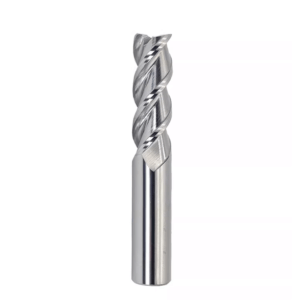
Initially, the client was using conventional 2-flute end mills. While chip removal was excellent, rigidity was insufficient during side milling and high-feed operations, causing tool runout and surface quality fluctuations. They then switched to 4-flute end mills to improve rigidity, but new issues appeared: limited chip removal space led to built-up edge formation, localized sticking, and even occasional tool breakage in deep cavity machining.
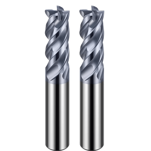
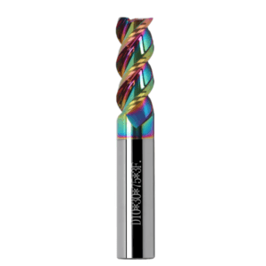
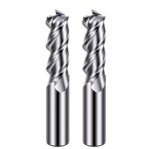
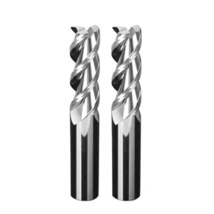
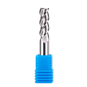
Through repeated projects, we found that the number of flutes is a key variable—but not the only factor. By switching to 3-flute end mills, adjusting helix angles, coatings, and corner radii, and matching cutting parameters to material and machine rigidity, we achieved a more stable balance between chip removal and tool strength. For example:
-
More rigid than 2-flute tools, allowing higher feed rates without vibration
-
Easier chip removal than 4-flute tools, especially in aluminum and semi-enclosed geometries
-
Stable execution of efficient milling strategies without constantly reducing spindle speed
However, simply switching to a three-flute end mill does not guarantee success. Many customers still face issues like tool chatter, abnormal wear, or reduced life. In our experience, the real bottleneck often lies in the combination of tool geometry, coating selection, clamping method, and toolpath strategy.
The key question is not whether to use a three-flute end mill—it is whether your 3-flute end mill actually delivers efficiency under your machining conditions. Are your current bottlenecks truly just tool-related?
Why do we choose a 3-flute end mill for efficient milling in actual machining?
When performing batch machining of aluminum alloy housings, we often face a common challenge: increasing feed rates to improve throughput can easily cause tool vibration, while reducing spindle speed lowers efficiency. Initially, the client used a 2 flute end mill, which handled chip removal well in aluminum, but lacked rigidity in deep groove and wide-width cutting, causing tool runout and inconsistent surface finish. Later, they tried a 4 flute end mill, which improved rigidity, but chip clogging and built-up edge frequently occurred under high-speed cutting, affecting production cycles.
After numerous experiments and adjustments, we found that a 3-flute end mill provides a stable balance between chip removal and tool rigidity. This is particularly effective in high-feed, light-to-medium depth milling strategies. A similar situation exists in steel machining: machining mold steel (~40 HRC) with a 2-flute tool resulted in slow machining, while a 4-flute tool experienced micro-vibration under high radial loads. Switching to 3-flute carbide end mills allowed us to maintain proper depth of cut and feed rate while achieving smooth chip evacuation and extended tool life—critical for large batch processing.
The Balance Between Chip Removal and Rigidity in a Three-Flute Structure
In aluminum machining, clients often aim to increase Material Removal Rate (MRR) but experience frequent vibration. At high feed rates, 2-flute tools remove chips well but are prone to vibration. Four-flute tools provide rigidity, yet limited flute space causes aluminum chips to cling to the tool, forming built-up edges and sometimes leading to breakage in deep grooves. By using 3-flute end mills for aluminum, adjusting helix angles and coatings, we achieved stable cutting at high feed rates with smooth chip removal, significantly improving MRR.
In steel machining, the results were similar. For instance, machining medium-deep grooves in 40Cr steel with a 4-flute tool caused micro-vibration and surface roughness, reducing tool life to only 60% of expectations. Switching to 3-flute carbide end mills reduced vibration, ensured uniform tool wear, and maintained continuous production. These examples highlight the stability advantages of three-flute tools in different materials and how geometric parameters and cutting strategies help achieve the optimal balance between chip removal and rigidity.
Typical Problems Encountered by Customers When Improving MRR
When discussing efficiency improvements with customers, we often see several recurring problems:
-
Tool chatter – High-speed aluminum or deep steel grooves often amplify runout, reducing surface quality and tool life.
-
Tool sticking – Improper helical flute design or coating selection can cause aluminum chips to adhere, forming built-up edges and increasing cutting resistance.
-
Tool chipping – Using the wrong number of flutes or hardness can sharply reduce tool life, sometimes after just a few hours of batch machining.
Using corner radius 3-flute end mills in high-feed aluminum machining reduces edge stress concentration while maintaining rigidity, lowering the risk of chipping. In steel machining, selecting high-hardness 3-flute carbide end mills and combining them with appropriate depth of cut and spindle speed significantly reduces vibration and extends tool life. These conclusions are drawn from repeated on-site verification, not theoretical speculation.
When do we not recommend using 3-flute end mills?
While 3-flute end mills excel in many high-efficiency scenarios, they are not always the best choice:
-
Deep grooving or extreme chip removal – Limited flute space can cause chip clogging or accumulation.
-
Low machine tool rigidity – Even with 3-flute carbide end mills, vibration and surface roughness can occur if rigidity is insufficient.
We evaluate usage based on machine tool rigidity, clamping system, depth of cut, and material hardness, rather than blindly pursuing efficiency.
In low-rigidity environments, like small desktop CNC machines or older machining centers, 3-flute end mills may not achieve high feed rates. In such cases, we advise clients to use 2-flute tools or reduce feed rates to maintain stability, preventing premature tool wear and preserving machining quality.
Core Advantages of 3-Flute Carbide End Mills in High-Efficiency Milling (Based on Field Data)
In projects machining aerospace aluminum parts and high-hardness steel molds, 3-flute carbide end mills demonstrated clear advantages. Using a high-speed spindle CNC machining center at 12,000–24,000 rpm for side and contour milling, tool stability was superior to HSS tools. Even after several hours of continuous cutting, the tools showed minimal runout and wear, particularly under medium depth and high feed conditions, significantly reducing interruptions caused by frequent tool changes.
Tracking tool wear across multiple batches, we found that solid carbide’s rigidity and wear resistance effectively resisted micro-vibrations and edge chipping. For aluminum, a suitable helix angle ensured smooth chip removal and consistent surface finish. For medium-hard steel, tool wear remained uniform, with no localized chipping. These on-site observations confirmed the reliability of 3-flute carbide end mills in high-efficiency milling.
Stability of Solid Carbide End Mills at High Spindle Speeds
In aluminum, HSS tools bent and vibrated at speeds above 15,000 rpm, causing unstable surfaces. Switching to 3-flute carbide end mills improved rigidity; at speeds above 20,000 rpm, the tools deformed minimally, and surface finish remained Ra 0.8–1.2 μm. The flute design maintained chip removal space, preventing chip retraction—a critical factor for high MRR operations.
For steel, batch machining of 40Cr mold steel using high-speed spindles with 3-flute carbide end mills resulted in uniform wear and no rapid edge chipping. Tool life was at least three times longer than HSS tools while maintaining stable cutting, reducing production cycle losses.
Actual Tool Life Difference Compared to HSS Tools
HSS tools showed significant edge wear and localized chipping after several hours, requiring frequent replacement and impacting cycle times. In contrast, 3-flute carbide end mills allowed continuous machining across multiple batches without tool changes. Tool change frequency dropped by ~60%, reducing downtime and manual intervention, making batch processing more predictable.
Tool life depends not only on material but also on the match between depth of cut and spindle speed. Using HSS tools for high MRR drastically reduces life, while carbide tools remain stable with increased feed and speed. This reinforces our approach of relying on practical experience rather than tool datasheets when optimizing cutting parameters.
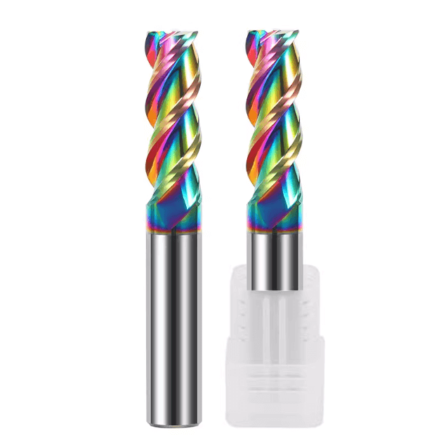
Differences in Performance of Different Coatings in Actual Machining
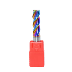
We tested coatings like TiAlN and DLC in aluminum machining. TiAlN performed stably in high-speed aluminum cutting, resisting wear and reducing sticking, though slight chip buildup occurred on high-silicon alloys. DLC performed better in steel, reducing chip buildup and thermal wear, but in aluminum, excessive surface hardness sometimes caused minor chip adhesion.
In one case, a client used a steel-specific coating on aluminum parts, causing increased cutting forces, severe chip buildup, and tool life less than half of expectations. After switching to TiAlN-coated 3-flute end mills for aluminum and adjusting feed and spindle speed, the sticking issue was resolved, preventing tool failure. This experience reinforced that coating selection and material matching are critical for reliable high-efficiency milling.
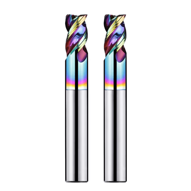
High-Efficiency Milling Experience with 3-Flute End Mills for Aluminum
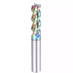
When mass-producing 6061 and 7075 aluminum alloy parts for our clients, we often encounter challenges with chip removal and surface finish under high feed rates and high MRR conditions. Tool geometry directly affects machining stability and tool life. Through numerous field tests, we observed that three-flute end mills with a large helix angle increase the tangential component of the cutting force in high-speed aluminum machining, improving chip evacuation and reducing chip retention in the flute. This is particularly noticeable during large-area contour milling and side milling, resulting in a uniform surface finish and reducing the need for secondary finishing.
We generally choose 3-flute carbide end mills with polished cutting edges for aluminum. Polishing reduces microburrs and surface roughness on the cutting edge, helping prevent built-up edge formation. In one aerospace aluminum project, unpolished tools accumulated chips quickly under high-speed cutting, while polished three-flute end mills maintained stable cutting even at wider cutting widths and higher feed rates, extending tool life by approximately 30%.
Commonly Used Tool Geometry Parameters in Aluminum Machining
For aluminum parts, we typically select three-flute end mills with:
-
Helix angles between 35–45°
-
Sharp cutting edges
-
Micro-polished surfaces
This geometry ensures cutting rigidity while providing sufficient space for chip removal. For thin-walled parts, we slightly increase the helix angle to reduce tool-workpiece vibration, allowing smooth chip evacuation. For contour machining with complex angle variations, corner radius 3-flute end mills help distribute stress and reduce edge chipping.
Matching tool diameter to cutting edge length is also critical. Excessively long three-flute end mills in shallow grooves often cause vibration and surface chatter. By controlling tool extension and choosing the proper diameter, we reduce wobble while maintaining high feed rates and efficient chip removal. These practices are drawn from long-term field experience in high-efficiency aluminum machining for European and American clients.
Spindle Speed and Feed Settings in High-Efficiency Milling
In batch machining of 6061 aluminum, we typically use:
-
Spindle speed: 18,000–22,000 rpm
-
Feed per tooth: 0.08–0.15 mm
For 7075 aluminum, which is harder, we slightly reduce feed to 0.06–0.12 mm/tooth, maintaining high spindle speed to sustain cutting efficiency. With machines of good rigidity, we increase side cuts to improve MRR. For low-rigidity or small CNC machines, we reduce depth of cut and feed to maintain tool stability.
We observed that over-reliance on tool capability while neglecting machine rigidity often leads to vibration and poor surface quality. Fine-tuning feed and depth according to machine stiffness ensures that 3-flute end mills for aluminum maintain continuous production without chipping under high-efficiency conditions. These parameter ranges are validated in multiple batch processes, not theoretical recommendations.
Practical Techniques for Avoiding Built-up Edges
Built-up edge (BUE) problems are common in high-speed, high-feed aluminum machining. Choosing an appropriate cooling or lubrication strategy is critical. Dry cutting benefits from polished edges and optimized helix angles, but for high-silicon aluminum or wide cuts, minimum quantity lubrication (MQL) helps prevent chip adhesion while lightly lubricating the cutting zone.
Tool surface treatment also matters. Polished or coated 3-flute carbide end mills reduce microburrs, improve chip flow, and prevent BUE formation. In client projects, we observed that improper surface treatment, even with reasonable cutting parameters, could still cause tool sticking, negatively affecting surface quality and tool life. By combining material, machine, and cutting parameters, we optimize tool geometry and surface treatment to ensure stable high-efficiency milling.
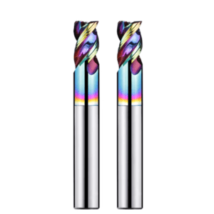
Experience with Corner Radius 3-Flute End Mills
High-feed aluminum and medium-hard steel parts often cause right-angle cutters to chip during high-speed side milling and deep grooves. In one 7075 aluminum project, a flat-bottom three-flute mill chipped at 0.12 mm/tooth feed, causing frequent production interruptions. After switching to corner radius 3-flute end mills, tool performance stabilized, surface roughness became uniform, and tool life increased by ~25%. Corner radius cutters distribute edge stress while maintaining rigidity, especially under high MRR conditions.
In steel machining, R-angle cutters also demonstrated advantages in contour cutting and transition areas: reduced vibration, uniform edge wear, and longer tool life. Stress concentration at cutting edges is a primary cause of chipping, which the rounded transition effectively mitigates.
Why We Prioritize R-Angle Cutters in High-Feed Machining
Right-angle milling cutters are prone to micro-cracks and localized chipping under high feed and speed, particularly in high-silicon aluminum or medium-deep steel grooves. A client using a right-angle 3-flute mill experienced chipping and surface roughness fluctuations. After switching to an R-angle cutter, tool life and cutting stability improved, enhancing efficiency without increasing downtime.
R-angle cutters increase rigidity and uniformly distribute cutting edge stress, especially in high-speed contour milling and transition areas. This is why we frequently recommend corner radius 3-flute end mills rather than blindly increasing depth of cut with flat-end mills.
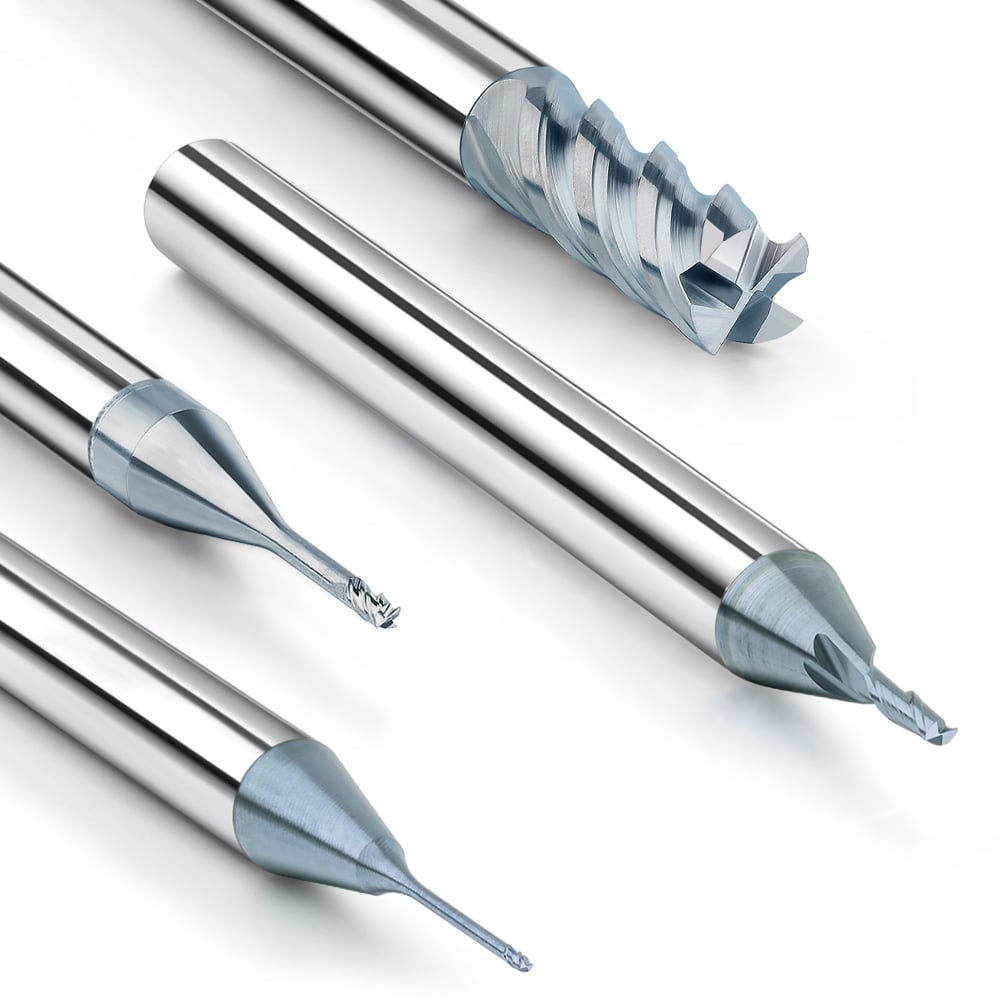
How Radius Affects Tool Life and Machining Efficiency
We have used radius cutters of 0.2 mm, 0.5 mm, and 1.0 mm in aluminum. Small radii suit detailed features but have lower load capacity and can chip under high feed. Larger radii bear more load and last longer, but may compromise access and machining accuracy in tight areas. In aerospace aluminum batch machining, we found 0.5 mm radius offered a balanced combination of stability, tool life, and precision.
Incorrect radius selection is common on-site. Too small a radius in medium-hard steel caused frequent breakage; too large a radius in thin-walled aluminum caused uneven transitions and chatter. We recommend choosing radius based on material, cutting depth, machine rigidity, and practical experience.
Experience with Toolpath and R-Angle Coordination
Toolpath design directly impacts stability with R-angle cutters. In aerospace aluminum, circular transitions reduce edge stress, improving stability in high-speed contour milling. Straight transitions concentrate loads, increasing vibration and breakage.
We also optimize toolpaths by reducing radial depth, adjusting cut sequences, and managing tool extension. Combined with radius-adjusted tools, these strategies reduce scrap rates and improve production continuity. Efficient milling depends on tool geometry, radius, and toolpath coordination, not just tool selection.
Common Problems in Efficient Milling and Our Solutions
Even with 3-flute carbide end mills, high feed and MRR conditions may produce vibration, abnormal wear, or unstable tool life. The root cause is often system-level: machine rigidity, clamping, tool extension, and toolpath strategy.
Tool performance also varies between batches of the same material. Efficient milling requires synergy between tool, machine, and strategy. We provide adjustment solutions tailored to machine performance, part material (6061, 7075, or medium-hard steel), and machining requirements to balance stability and efficiency.
On-Site Handling of Chatter Issues
Excessive tool extension is a common cause of vibration. For aerospace aluminum contours, we reduced extension and adjusted fixture height to minimize cutting length, alleviating chatter. Toolpath adjustments—like segmented cutting or changing cutting direction—also help stabilize corner radius 3-flute end mills at high feed rates, achieving better efficiency-surface quality balance than simply reducing feed.
Analysis of Abnormal Tool Wear
Uneven wear, chipping, and burning often indicate abnormal wear. Uneven wear often stems from excessive radial depth or unstable clamping; chipping occurs at high feed or hard materials; burning arises from high cutting temperatures or improper coatings. Using a steel-specific coated 3-flute mill on 7075 aluminum can accelerate adhesion and overheating, reducing tool life.
We adjust parameters or use material-appropriate coatings, e.g., TiAlN-coated 3-flute tools for aluminum, often mitigating abnormal wear. Experience-based judgment ensures we avoid unnecessary tool replacement while maintaining production cycles.
Typical Causes of Unstable Tool Life
Insufficient machine rigidity is a major factor. Micro-backlash or bed vibrations reduce tool life even with high-quality 3-flute carbide mills. Optimizing fixtures, reducing extension, and adjusting feed reduces dynamic load, extending lifespan.
Clamping issues also impact stability. For large-diameter or long-edge tools, slight deviations cause uneven wear. We recommend upgrading clamps or choosing shorter cutting edge lengths, effectively stabilizing tool life while maintaining efficiency in high feed and high MRR conditions.
High-Efficiency Milling Strategies for 3-Flute End Mills Across Different Materials
When providing batch machining solutions for clients, we have observed that different materials place vastly different demands on tool geometry, cutting parameters, and cooling strategies. Even the same 3-flute carbide end mill behaves differently on aluminum alloys, stainless steel, or die steel. Through extensive field experience, we have developed material-specific high-efficiency milling strategies to ensure stable tool life and consistent surface finish under high MRR and high feed conditions.
We emphasize that high-efficiency milling is not solely dependent on tool performance. A comprehensive balance of tool, machine rigidity, clamping system, and cutting parameters is critical. Each material requires fine-tuning based on workpiece shape, depth of cut, and spindle speed. Proper adjustments help reduce vibration, edge chipping, and chip buildup, improving production continuity.
Aluminum Alloys (Key Application)
For aluminum machining, we typically employ high-speed spindle speeds (18,000–22,000 rpm) with high feed per tooth (0.08–0.15 mm/tooth) to fully leverage the chip removal and cutting rigidity of a 3-flute end mill. In aerospace aluminum projects, using a three-flute carbide end mill with a large helix angle and polished cutting edges ensured smooth chip evacuation and uniform surface finish during high-speed contour milling and side milling. This strategy significantly improves MRR while maintaining stable tool life.
Different aluminum grades, such as 6061 and 7075, require different tool parameters. Due to its higher hardness, 7075 produces greater cutting forces at the same feed rate. Reducing the cutting thickness while maintaining high spindle speed helps prevent excessive heat buildup. Fine-tuning the helix angle, corner radius, and feed rate is key to achieving efficient aluminum machining.
Stainless Steel Machining Precautions
Stainless steel machining requires special attention to cutting temperature and tool friction, as excessive heat can cause edge hardening or tool sticking. For example, in machining 316L stainless steel, conventional feed rates led to edge burning after only a few parts. By reducing radial depth of cut, increasing cutting fluid flow, and using TiAlN-coated 3-flute carbide end mills, we significantly extended tool life and maintained consistent surface finish.
Tool geometry is crucial. Increasing helix angle and corner radius helps distribute the cutting load, reducing localized stress. Combined with optimized toolpaths and cooling, these measures prevent premature tool failure and maintain production continuity.
Die Steel and High-Hardness Material Strategies
For die steel or high-hardness materials (HRC 45–55), we adopt shallow depth, high-speed cuts. In machining 40Cr steel molds, we use 3-flute carbide end mills with cut depths of 0.5–1 mm. Coupled with high-rigidity clamping and optimized toolpaths, this ensures uniform wear and prevents edge chipping.
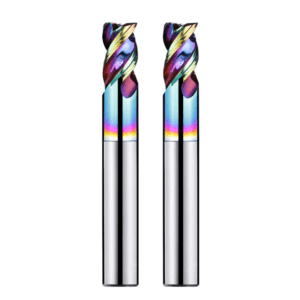
We prioritize solid carbide three-flute end mills and, where needed, TiAlN or DLC coatings to improve wear resistance and heat tolerance. Cutting parameters are adjusted based on tool diameter, cutting edge length, and machine rigidity to ensure controllable tool life. Experience shows that for high-hardness materials, matching tool geometry with cutting strategy is more effective than simply increasing feed rates.
Helping Clients Choose Reliable 3-Flute End Mill Manufacturers
Selecting a tool supplier is not solely about price. Low-cost 3-flute end mills often lead to frequent downtime during high-MRR aluminum or medium-hard steel machining. In one 7075 aluminum batch, inexpensive tools chipped under high feed, interrupting production for over half a day. Replacing them with validated 3-flute carbide end mills restored production continuity and extended tool life.
Supplier selection should match material, process, and technical support needs. Low-cost tools often exhibit inconsistent substrate hardness and coating thickness, leading to runout and instability under high-speed machining. In contrast, reliable suppliers provide tools with uniform substrate, consistent coating, and strict runout control, ensuring stable cutting for high-feed aluminum and medium-hard steel. This reduces downtime and tool changes in mass production.
Evaluating Tool Quality Beyond Price
Actual tool performance is the core indicator of supplier value. One aerospace aluminum customer initially tried low-priced tools but experienced frequent vibration and surface roughness. After switching to tested 3-flute carbide end mills with optimized feed and depth, tool stability improved, and MRR increased. Low-cost tools may save money upfront, but production losses often outweigh the initial savings.
We recommend evaluating suppliers by tool stability, lifespan, and consistency, using on-site trial cuts, batch verification, and empirical data. This ensures the selected tool matches the material properties, machine rigidity, and toolpath strategy, not just the cost.
Key Supplier Evaluation Indicators
-
Base Material Quality: High-quality carbide with uniform grain and hardness ensures stable cutting at high speed and feed.
-
Coating Consistency: Thickness and adhesion affect heat resistance and chip evacuation.
-
Tool Runout Control: Even minor eccentricity amplifies vibration and edge wear during high-speed aluminum or steel machining.
We conduct batch tests for runout, wear uniformity, and surface finish to verify suppliers. For example, aerospace aluminum contours machined with tested 3-flute end mills maintained consistent edges and finishes at 12,000–22,000 rpm high-feed operations.
The Value of OEM-Customized End Mills
Clients often have unique machining requirements: thin-walled aluminum, high-hardness steel molds, or complex contours. Standard tools may still vibrate or produce chip buildup. In one aerospace aluminum project, we collaborated with a supplier to customize a 3-flute end mill with an optimized radius (R), helix angle, and coating thickness, enabling stable high-feed cutting and extended tool life.
For mass production, customized tools reduced tool change frequency by over 50%, stabilized production cycles, and achieved desired surface finish. OEM solutions address specific machining challenges while optimizing cost and efficiency.
High-Efficiency Milling Case Studies from Real-World Projects
Through years of providing on-site technical support to European and American machining clients, we have observed that 3-flute end mills, combined with optimized cutting parameters and tool geometry, can significantly improve the machining efficiency of aluminum alloys and steel under high-feed and high-speed milling conditions. Our real-world case studies illustrate practical solutions, helping clients select the right tools and parameters for different materials and machining scenarios.
These examples not only demonstrate tool performance but also highlight the importance of machining strategies, toolpath design, and machine tool rigidity in achieving efficient milling. By conducting on-site parameter optimization—testing variations in flute count, helix angles, and coatings—we have developed reliable strategies for stable, high-efficiency machining. Experience shows that successful milling depends on system-level optimization, not only on tool choice or price.
Case Study: Improving Aluminum Alloy Machining Efficiency (Over 30% Improvement)
In an aerospace project, a client initially used a standard 2-flute end mill. Despite high spindle speeds, vibration and surface roughness issues persisted, limiting production efficiency. By switching to a 3-flute end mill for aluminum, optimizing the helix angle, and adjusting feed strategy, machining efficiency improved by approximately 30%.
Key observations:
-
Increased feed rate while maintaining a stable depth of cut.
-
Consistent surface finish with minimal built-up edge formation.
-
Smooth chip removal and improved contour accuracy.
Field experience shows that efficiency gains rely not only on flute count but also on matching tool geometry with machine rigidity, depth of cut, and feed rate. For high-MRR aluminum machining, helix angle, corner radius, and toolpath strategy must be optimized for holistic system efficiency.
Improved Tool Life Using 3-Flute Carbide End Mills
During the same project on aluminum and medium-hard steel parts, the client initially used HSS tools with a lifespan of only a few hours, resulting in frequent replacements and downtime. Switching to 3-flute carbide end mills with optimized feed and depth parameters increased tool life by approximately three times.
Key outcomes:
-
Significant reduction in tool costs.
-
Increased production continuity.
-
Stable batch machining cycles with minimal interruptions.
High-speed, high-feed milling with 3-flute carbide end mills ensures uniform tool wear, reduced edge chipping, and consistent surface quality, minimizing production risks caused by tool failure or downtime.
Solving Edge Chipping with Corner Radius 3-Flute End Mills
In a hard steel mold project, right-angle 3-flute end mills caused frequent edge chipping during high-speed contour milling, leading to downtime and rework. By using corner radius 3-flute end mills and optimizing radius and cutting parameters:
-
Edge chipping was significantly reduced.
-
Contoured surfaces became uniform.
-
Tool life increased.
-
Production continuity improved.
Our structured “problem → solution → result” approach:
-
Analyze causes of edge chipping (high feed, concentrated load, right-angle edges).
-
Select a suitable R-angle 3-flute end mill and optimize the toolpath.
-
Record tool life and surface quality.
This method establishes replicable high-efficiency milling standards for mass production.
Our Experience in Promoting 3-Flute End Mills
Years of supporting European and American clients have taught us that efficient milling is not simply about increasing the number of cutting edges. Many clients focus solely on flute count, neglecting tool geometry, helix angle, corner radius, and coating compatibility, often resulting in vibration, chipping, or unstable tool life in high-speed aluminum milling, mold steel deep grooves, or high-hardness contour cutting.
We have concluded that the core of high-efficiency milling lies in system-level optimization: machine and tool rigidity, machining parameters, and toolpath strategy. Even the highest-performance 3-flute carbide end mills cannot achieve stable high-MRR milling if machine rigidity or toolpath design is inadequate. Coordinating tool geometry, coating selection, cutting parameters, and toolpath is essential for consistent efficiency and extended tool life across aluminum, steel, and die steel machining.
Common Customer Misconceptions
-
Blindly increasing flute count:
-
2-flute tools remove chips easily but lack rigidity.
-
4-flute tools are rigid but prone to chip clogging.
-
3-flute end mills offer a balanced solution for aluminum and medium-hard steel, verified through extensive on-site testing.
-
-
Neglecting tool geometry:
-
Helix angle, R-angle, and polished edges affect built-up edge formation, vibration, and chipping.
-
Before adjusting feed or depth, ensure the tool geometry suits the material and cutting conditions.
-
High-Efficiency Milling Requires Holistic Optimization
High-efficiency milling depends on coordinated optimization of tools, machine rigidity, cutting parameters, and toolpath. For example, in mold steel machining, tool wear and vibration occurred despite top-tier 3-flute carbide mills due to machine-tool mismatches. Adjusting tool extension, toolpath, and feed parameters stabilized performance and improved production continuity.
Achieving stable tool life and surface quality requires comprehensive consideration of:
-
Tool geometry and coating
-
Machine rigidity and clamping
-
Toolpath strategy and cutting parameters
If tool life or surface quality fluctuates, check these factors first before simply adjusting feed or replacing tools.
Practical Advice from Long-Term Technical Support
-
Conduct small-batch tests (3–5 cuts) before mass production.
-
Record tool life, surface finish, material type, machine rigidity, and toolpath strategy.
-
Compare tools from different suppliers to select the best match.
-
Use empirical data to minimize tool breakage and chip buildup, ensuring consistent high-efficiency milling.
FAQ: Frequently Asked Questions About Efficient Milling
Q1: Is a 3-flute end mill suitable for all materials?
A: Not always. For aluminum alloys (6061, 7075), a 3-flute end mill with large helix angle and polished edge provides smooth chip removal and stable tool life. For mold steel or stainless steel, improper depth of cut or insufficient machine rigidity can cause chipping. Evaluate based on tool geometry, coating, and machining conditions.
Q2: Why can high spindle speed reduce efficiency?
A: Excessive spindle speed can amplify vibration if cutting force exceeds tool rigidity, especially in deep grooves or wide cuts. Adjust feed, radial depth, and assess machine rigidity before increasing speed.
Q3: How do I determine if parameters are reasonable?
A: Observe tool life, machined surface, and chip removal. If vibration, sticking, or localized chipping occurs, adjust depth of cut, radial depth, and feed rate. Small-batch tests help define optimal ranges.
Q4: When should a tool be replaced?
A: Replace based on edge wear and machining performance, not solely time or part count. Indicators include edge chipping, severe wear, surface ripples, or abnormal cutting forces. Track tool life relative to material, geometry, and coating for optimal replacement timing.