In the field of micro-part manufacturing, dimensional tolerances often directly determine assembly feasibility and functional reliability. When part features reach sub-millimeter or even micron levels, even minor processing fluctuations are magnified, and traditional machining methods gradually reveal limitations in dimensional consistency and repeatability. In this context, micro end milling has become an essential method for achieving high tolerance control in micro parts.
Unlike conventional milling, micro end milling relies on extremely small-diameter micro end mills to remove material in a controlled manner. This process demands precise tool geometry, stable spindle performance, and well-matched cutting parameters. By carefully selecting micro end milling bits and controlling tool runout, cutting load, and chip formation, dimensional drift during the machining of micro-features can be significantly reduced, improving overall tolerance stability.
Micro-part machining often involves holes, micro-grooves, and thin-walled structures, posing a dual challenge for dimensional consistency and edge accuracy. Micro end milling allows precise control over actual machining dimensions through smaller cutting depths and controlled material removal. This method minimizes the impact of tool deflection and ensures stable geometry across multiple repeated operations.
As micro-part structures become more complex, standard tools may not meet stringent tolerance requirements in certain scenarios. Custom micro end mills, designed for specific materials and geometries, can be optimized in terms of blade length ratio, edge geometry, and cutting stability, enhancing the reliability of micro end milling in high-precision tolerance control. This optimization is a key reason why micro end milling continues to be used in high-end micro-part manufacturing.

Core Machining Challenges in Micro-Part Tolerance Control
Tolerance control in micro-part machining results from the combined effects of size scale, material properties, and processing system stability. When workpiece features shrink to the micron level, previously negligible error sources quickly become critical, making dimensional consistency and repeatability difficult to achieve. Even with highly precise techniques like micro end milling, several unavoidable machining challenges remain.
Microstructures often feature high density, small pitch, and complex geometries, placing greater demands on micro end mills than conventional milling. Simultaneously, the stress state, material removal method, and heat distribution of micro end milling bits at extremely small diameters directly influence final dimensions. Without systematic control, even high-precision equipment and tools may fail to consistently achieve target tolerances.
The Impact of Dimensional Amplification Effects on Micro-Scale Features
At micron-level dimensions, errors are no longer “absolute values” but exhibit significant amplification. For example, tool runout or feed fluctuations of just a few microns can translate into considerable deviations in micro-groove width or micro-hole diameter. This effect is especially evident when micro end milling is used for micro-profiles and micro-cavities.
Even minimal spindle instability, tool clamping errors, or thermal deformation can cumulatively impact final dimensions. For parts relying on micro end milling for high-precision contours, this dimensional amplification is often the primary reason tolerances are difficult to converge.
Amplified Effects of Material Non-Uniformity in Micro End Milling
Material non-uniformity may have limited impact in conventional machining, but it is significantly magnified in micro end milling. Variations in grain orientation, hardness distribution, and localized stress concentrations change cutting loads on micro end milling bits, affecting actual material removal.
When machining aluminum alloys, stainless steel, or copper alloys, these variations can cause fluctuations in cutting resistance, leading to slight tool deviations or elastic deformation. Such effects are difficult to eliminate with simple parameter adjustments and continuously influence micro-feature dimensional stability.
Natural Limitations of Small Tool Diameter on Machining Stability
Micro end mills have extremely small diameters, which improves detailed machining but reduces structural rigidity. Smaller tools are less able to withstand lateral and axial forces, making them susceptible to deflection, vibration, or even instantaneous instability, particularly in deep grooves and long overhangs.
Even high-quality micro end milling bits can suffer from reduced stability if cutting depth and feed strategies are not properly controlled, negatively affecting tolerance control.
Core Machining Mechanism of Micro End Milling in Tolerance Control
In micro-part machining, stable tolerance control depends not only on equipment accuracy or measurement methods but also on the predictability of the material removal process itself. The reason micro end milling achieves superior dimensional consistency in high-precision micro-structures is that its cutting mechanism is highly controllable. Variations in cutting load can be confined within a safe range, minimizing the influence of random errors on final dimensions.
By properly matching tool diameter, cutting edge geometry, and cutting parameters, micro end milling maintains a stable cutting state with extremely small material removal amounts. This stability ensures that each pass removes material close to the theoretical value, providing a solid foundation for consistent tolerances across repeated machining operations.
Direct Impact of Micro-Cutting Thickness on Dimensional Consistency
In micro end milling, the cutting thickness of a single pass is typically at the micrometer level. This thickness determines whether material is removed in a stable cutting manner or is partially sliding or smeared. When the cutting thickness approaches or slightly exceeds the minimum chip thickness, the material removal process becomes predictable, and actual dimensions are closer to design specifications.
If cutting thickness is not carefully controlled, material may be squeezed rather than cut, causing unpredictable deviations in micro-feature dimensions. Precisely controlling feed rate and the effective cutting edge length improves dimensional repeatability in micro-profiles and micro-grooves across multiple operations.
The Role of Micro End Mill Cutting Edge Geometry on Actual Cutting Dimensions
At micro-scale machining, the cutting edge geometry—including edge radius, rake angle, and relief angle—has a decisive effect on actual dimensions. Properly designed edges ensure uniform cutting force distribution and stable tool trajectory, reducing dimensional drift.
Conversely, asymmetrical or unevenly worn edges can introduce offsets, causing deviations from the theoretical path. For high-precision micro-parts, these small variations are often directly reflected in tolerance fluctuations.
Quantitative Control Logic of Tool Deflection in Micro End Milling
Tool deflection is unavoidable at extremely small diameters, but it can be controlled. By managing cutting force, overhang length, and cutting depth, deflection becomes a predictable variable rather than a random factor.
When cutting loads remain stable, tool deflection exhibits a repeatable pattern. This consistency allows machining dimensions to stay stable over multiple passes. Quantitative control of deflection is a key reason micro end milling excels in tolerance control of micro-parts.
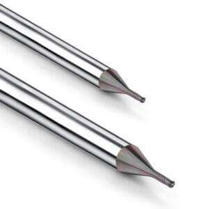
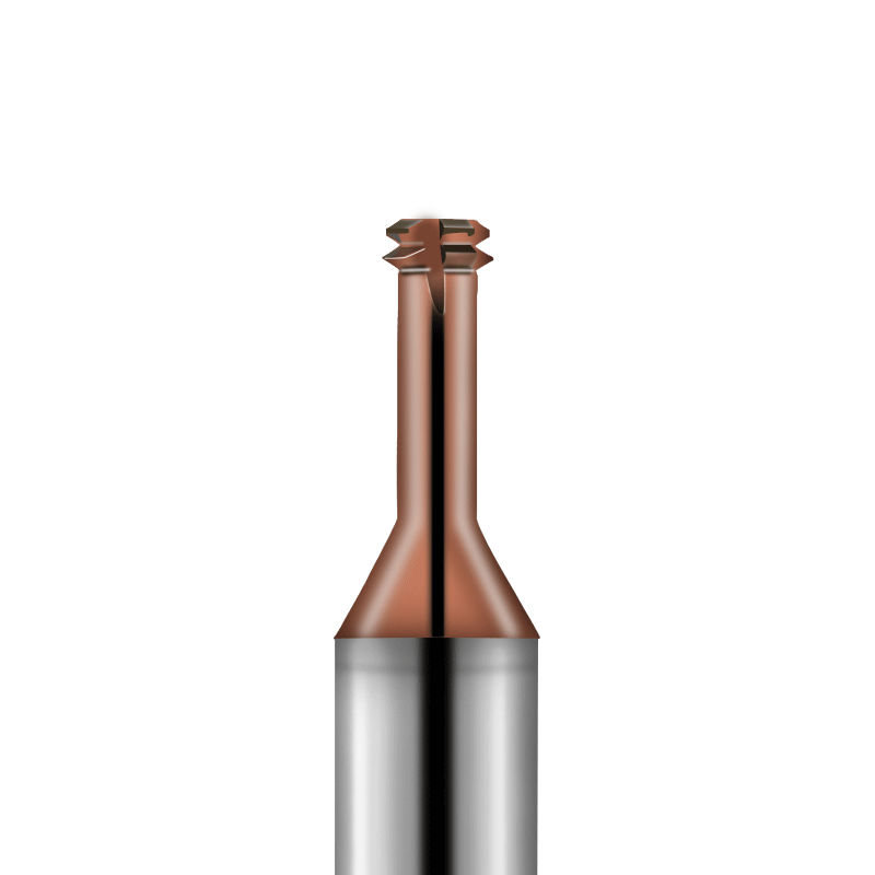
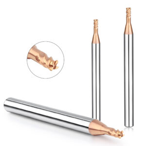
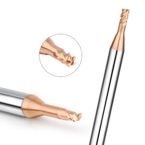
The Decisive Role of Micro End Milling Bits in Micro-Tolerance Stability
The precision and structural characteristics of the tool itself directly determine machining stability and repeatability. Even with high-precision equipment and optimized cutting parameters, deviations in tool diameter, geometry, or coating can cause dimensional drift. In micron-level micro-part machining, the quality, consistency, and material removal capability of micro end milling bits are critical for achieving high tolerance stability.
High-precision tools ensure uniform cutting force distribution and minimize offsets. Their cutting edge geometry and coating properties also stabilize chip formation, maintaining micro-feature dimensions. Choosing the right diameter, flute count, helix angle, and coating type optimizes dimensional repeatability and machining stability for different materials and microstructures.
Relationship Between Micro End Milling Bit Diameter Tolerance and Actual Machining Dimensions
Even slight diameter deviations are magnified in micro-part machining, affecting groove width, hole diameter, or micro-protrusions. Using high-precision micro end milling bits with tightly controlled diameter tolerances minimizes errors.
Tool diameter stability also ensures uniform cutting force distribution. Bits with higher diameter consistency maintain stable trajectories across multiple passes, improving dimensional repeatability and batch tolerance stability.
Influence of Number of Flutes and Helix Angle on Dimensional Repeatability
Flute count and helix angle are key factors in cutting performance. Too few flutes concentrate cutting loads, causing micro-vibration and geometric inaccuracies. Too many flutes can increase chip accumulation, leading to tool deflection.
The helix angle influences cutting force direction and chip evacuation. An optimal helix angle disperses cutting forces, reduces vibration, and improves chip flow in micro-cutting, enhancing micro-feature dimensional stability.
Suppression Effect of Coating Consistency on Micro-Dimensional Fluctuations
Coatings on micro end milling bits extend tool life and stabilize cutting. Uniform coatings reduce friction, minimize micro-deviations, and suppress force fluctuations. For high-hardness or viscous materials, consistent coatings improve lubrication and thermal stability, ensuring repeatable dimensions and reliable tolerance control.
Overall, micro-part dimensional stability largely depends on tool diameter tolerance, flute design, helix angle, and coating consistency. Rational selection and optimization of these parameters are essential for high-precision tolerance control and reliable micro-part manufacturing.

The Real Impact of Spindle Runout and Clamping Systems on Tolerance Control
Even with optimized tool geometry, cutting parameters, and high-precision equipment, small spindle runout and clamping system errors can critically affect dimensional consistency. In micro end milling, due to the extremely small tool diameter, even micron-level runout can lead to deviations from design dimensions. The rigidity and stability of the clamping system influence the forces acting on the tool. Any instability or gap in the tool holder can cause tool displacement during cutting, impacting micro-grooves, micro-holes, and thin-walled structures.
Strict control of spindle runout and clamping can minimize tool displacement effects, making material removal more predictable and improving tolerance consistency and repeatability in micro-part machining.
How Runout Values Directly Translate into Dimensional Errors in Micro End Milling
Micro end milling bits typically range from 0.1–1 mm in diameter. Even 1–2 μm spindle runout can be amplified in machined dimensions, causing significant deviations in micro-hole diameters or groove widths. This error primarily originates from radial tool oscillation, which diverts the cutting path from the theoretical trajectory.
For high-precision micro-structures, there is an almost linear relationship between runout and dimensional deviation. Strict spindle concentricity and vibration control are therefore fundamental to maintaining machining tolerances.
The Impact of the Tool Holder System on Micro End Mill Stability
Tool holder rigidity and precision directly influence micro end mill stability. Small gaps or misalignment at the tool holder-spindle interface can amplify tool displacement under cutting forces, especially in deep groove or long overhang machining.
High-precision, rigid tool holders reduce radial vibration and ensure stable cutting trajectories at micro-cutting depths, which is crucial for high repeatability and tolerance stability in micro end milling.
Practical Methods for Reducing Runout to Improve Tolerance Consistency
Key methods to minimize runout include optimizing spindle concentricity, using high-precision tool holders, and ensuring precise tool clamping. Spindle maintenance, balancing, and vibration control reduce radial and axial runout. Proper tool holder calibration and minimal tool overhang help distribute forces evenly and reduce deflection-induced deviations.
In micro-part mass production, monitoring spindle vibration and tool offsets, combined with micro end milling bit life management, effectively suppresses the impact of runout, improving dimensional consistency and repeatability.

The Role of Cutting Parameters in Tolerance Control during Micro End Milling
In micro-part machining, cutting parameters influence not only processing efficiency but also dimensional consistency and the stability of micro-feature tolerances. Unlike conventional milling, micro end milling is highly sensitive to parameters such as feed rate, spindle speed, and cutting depth. Even micron-level variations can cause dimensional deviations or changes in surface roughness. Precise control of cutting parameters keeps the material removal process within a stable range, enabling high-precision tolerances for microstructures.
In practice, cutting parameters should be treated as controllable variables, set and optimized through theoretical calculations, tool performance analysis, and machining simulations. Tool geometry, material properties, and machine tool rigidity all influence parameter selection. Correctly matching cutting parameters to tool diameter, overhang length, and material properties ensures repeatable dimensions and batch stability.
The Mechanism of Feed Rate’s Influence on Micro-Dimensional Linear Errors
Feed rate directly determines single-tooth cutting thickness in micro end milling bits. Excessive feed rates increase cutting forces, causing tool deflection or vibration, leading to linear errors in micro-groove width, hole diameter, or micro-protrusions. Conversely, very low feed rates may reduce deflection but cause incomplete cutting, material buildup, or surface tearing.
By matching the feed rate with the diameter and number of flutes of the micro end milling bits, the material removal per cut remains stable, achieving linear dimensional control. This controllable feed strategy is fundamental for high-tolerance machining.
How Spindle Speed Fluctuations Disrupt the Dimensional Consistency of Micro-Features
Spindle speed fluctuations alter cutting speeds, affecting cutting forces and material removal efficiency. At micron-level scales, this can lead to dimensional deviations, increased surface roughness, or irregular contours. Even minor spindle speed variations can produce measurable errors in hole diameters or micro-groove widths.
Maintaining a high-rigidity spindle, setting optimal control parameters, and using high-precision motors and drives can minimize these effects, ensuring consistent micro-feature dimensions during repeated machining.
Safe Window for Axial Cutting Depth in Micro-End Milling Tolerance Control
Axial cutting depth determines the material thickness removed per pass, affecting tool deflection and cutting forces. Excessive depth increases the risk of vibration, producing oversized features; insufficient depth reduces efficiency and may create uneven force distribution, impacting dimensional stability.
By considering tool diameter, overhang length, and material hardness, a safe cutting depth range can be defined. This approach ensures dimensional tolerances and extends the life of micro end milling bits, improving batch processing reliability.

Influence of Material Properties on Micro End Milling Tolerance Stability
In miniature part machining, the material’s physical and mechanical properties directly impact dimensional consistency and tolerance stability. Hardness, elastic modulus, stress distribution, and cutting behavior can amplify small errors during the micro end milling process, resulting in dimensional drift in micro-grooves, holes, or thin-walled structures. Even with highly precise tools and machines, achieving consistent high-precision tolerances is difficult without accounting for material properties.
The outcome of micro end milling depends not only on tool geometry and cutting parameters but also on the material’s cutting response. Material rebound, deformation, or localized plastic flow under cutting force can alter actual dimensions. Therefore, selecting the appropriate micro end milling bits for each material, optimizing cutting parameters, and controlling tool deflection are essential to maintain dimensional repeatability and micro-tolerance stability.
Dimensional Rebound Problem in Aluminum Alloy Micro-End Milling
Aluminum alloys, with low elastic modulus and high plasticity, are prone to material rebound during the machining of micro-grooves or thin walls. This springback can lead to oversized features, especially in micro-groove width and micro-protrusion height.
To control springback, optimize cutting depth and feed rate while selecting micro end milling bits with high diameter accuracy and rigidity. Proper tool geometry and cutting parameters ensure that springback remains within acceptable limits without compromising machining efficiency.
Dimensional Drift Phenomenon in Stainless Steel Micro-Feature Machining
Stainless steel’s high hardness and work hardening make it susceptible to dimensional drift. Under high cutting forces, slight tool deflection and material elastic recovery may gradually alter micro-hole diameters or groove widths, particularly in deep grooves or long overhang features.
Using high-rigidity tool holders, optimizing micro end milling cutter edge geometry, and controlling axial depth and feed rate can minimize cutting force fluctuations, reducing drift and improving tolerance stability for miniature parts.
Impact of Micro End Milling Bit Selection on Tolerances in Copper Machining
Copper and its alloys have high thermal conductivity and adhesion, increasing the risk of chip sticking and micro-vibrations, which negatively affect dimensional repeatability. Choosing micro end milling bits with proper coatings and geometry enhances chip evacuation and tool thermal stability, improving tolerance control.
Cutting edge length, number of flutes, and helix angle directly influence cutting force distribution, which is especially critical in copper machining. Correct tool selection reduces micro-dimensional fluctuations and ensures consistent thin-walled and micro-hole features across multiple machining operations, supporting reliable mass production of high-precision miniature parts.

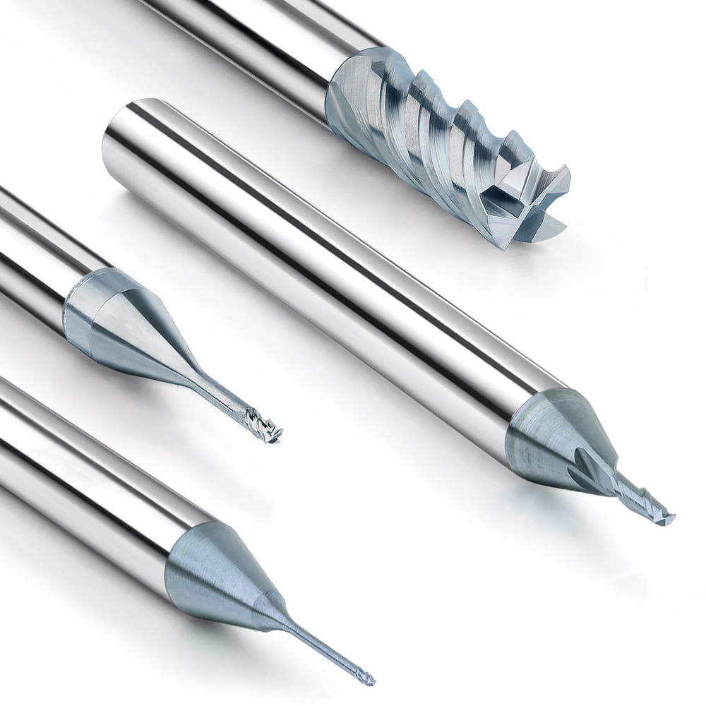
Why Custom Micro End Mills Offer Advantages in Micro-Tolerance Control
Achieving high-precision tolerances in miniature part machining requires not only the right tool diameter and cutting parameters but also optimization for specific machining conditions. Standard micro end mills are versatile but may not perform optimally under extreme tolerance requirements. Custom micro end mills, designed for the part material, micro-feature geometry, and machining depth, significantly improve dimensional repeatability and machining stability.
Custom tools optimize blade length ratio, cutting edge geometry, and coating configuration. This creates more uniform cutting forces, reduces tool deflection, and suppresses dimensional deviations caused by material rebound or micro-vibrations. Consequently, micro end mills can consistently maintain tolerance consistency when machining micro-holes, grooves, or thin-walled structures, ensuring reliable high-precision results.
Structural Bottlenecks of Standard Micro End Mills under Extreme Tolerances
Standard micro end mills reveal structural limitations in extreme tolerance machining. Blade length, diameter, and overhang ratios are designed for general use rather than part-specific optimization. This can result in deflection, vibration, or thermal deformation at micro-cutting thicknesses, causing dimensional drift.
Additionally, standard tool flute count and cutting edge shape may not align with the requirements of high-hardness or viscous materials, causing chip accumulation or localized overcutting during microstructure machining. These factors collectively reduce dimensional stability under extreme tolerances.
Improvement in Dimensional Stability through Customized Blade Length and Cutting Edge Ratio
Optimizing blade length and cutting edge ratio in custom tools reduces cutting force concentration and tool deflection. A shorter effective blade length or optimized cutting edge angle minimizes vibration in deep grooves and thin-walled structures. Enhanced cutting edge geometry improves chip evacuation, reduces thermal deformation or sticking, and ensures stable micro-dimension machining.
This customization ensures the actual material removal per cut matches theoretical values, providing a reliable foundation for high-precision tolerance control.
Tolerance Benefits of Custom Micro End Mills in Specific Microstructures
In complex microstructure machining, custom tools offer significant advantages. Custom micro end mills, optimized for micro-holes, grooves, or protrusions, achieve high repeatability while maintaining cutting stability. Selecting the correct number of cutting edges, helix angle, coating, and diameter tolerance reduces the impact of drift and micro-vibrations, improving dimensional consistency. In high-volume production, this targeted optimization increases yield, reduces rework, and ensures the reliability and stability of microstructure machining.
Control Strategies for Tolerance Consistency in Batch Machining of Micro-Parts
In batch micro-part machining, achieving dimensional consistency and tolerance stability is a primary concern. Even with proper tolerance control for individual micro end milling operations, factors such as tool wear, accumulated heat, and machine vibration can amplify dimensional deviations during batch processing. Through systematic tool management, dimensional monitoring, and compensation strategies, tolerance fluctuations can be effectively minimized, improving production yield and ensuring consistent quality for each microstructured part.
Batch machining strategies involve not only tool performance and lifespan but also cutting parameter optimization, machining sequence design, and dimensional compensation. By analyzing tool wear patterns, cutting force variations, and deviation trends, manufacturers can establish predictable control schemes for stable batch machining of micro-parts.
The Impact of Tool Life Cycle on Dimensional Drift
During micro end milling, tools gradually wear. Blunt edges and micro-cracks alter cutting thickness and force distribution, causing micro-grooves, holes, and thin-walled features to drift from their target dimensions. In high-precision machining, even slight wear can produce measurable dimensional changes.
By monitoring tool life and mapping the wear curve of micro end milling bits, operators can predict when performance will degrade and replace or resharpen tools accordingly. This strategy effectively controls dimensional drift and maintains tolerance consistency in batch production.
Practical Methods for Dimensional Compensation in Micro End Milling
Dimensional compensation is essential for batch machining. Measuring the first few parts and establishing a deviation model allows fine-tuning of tool paths, feed rates, or cutting depths in subsequent operations.
This approach addresses tool wear, machine micro-deviations, material rebound, and micro-vibrations, ensuring stable control of microstructure dimensions. When combined with high-precision measurement systems, dimensional compensation creates a closed-loop control, enhancing tolerance maintenance in micro end milling.
How to Reduce Batch Tolerance Fluctuations Through Tool Management
Systematic tool management reduces batch tolerance variations. Key measures include:
-
Controlling diameter tolerance and cutting edge geometry of micro end milling bits.
-
Scheduling tool replacement cycles based on usage and material.
-
Matching tool overhang length with cutting parameters.
-
Regularly checking tool holder and spindle rigidity.
By recording tool performance under different materials and conditions, adjustments can ensure stable cutting conditions for every operation. Combined with dimensional compensation, these strategies minimize tolerance fluctuations in batch machining, improving both production stability and product reliability.
Key Points for Dimensional Verification and Tolerance Confirmation After Micro End Milling
Accurate dimensional verification and tolerance confirmation are critical in micro-part machining. Even with optimized tools, cutting parameters, spindle stability, and material considerations, ineffective measurement can allow deviations to go undetected. Professional verification methods provide empirical evaluation of process optimization and tool management measures, forming a closed-loop system to ensure dimensional consistency and tolerance stability.
Verification extends beyond single-part inspection. It tests the entire micro end milling process, including micro-cutting thickness control, tool deflection management, spindle runout suppression, cutting parameter optimization, and material compensation. Scientific measurement identifies error sources, provides accurate feedback, and ensures that each batch meets design specifications.
Limitations of Microscopic Measurement in Micro End Milling Tolerance Verification
Microscopic measurement is common but has limitations. Micro-holes, grooves, and thin-walled structures are tiny and complex. Contact probes or optical measurement may induce local compression, projection errors, or parallax, causing discrepancies. Additionally, effects of tool wear, material springback, and micro-vibrations may be masked, preventing full reflection of the true tolerance state. Multiple measurement methods and repeated measurements are needed to minimize misjudgment.
The Impact of Measurement Methods on “True Machining Dimensions”
Different methods yield different representations of micro end milling results. Contact measurement may compress thin walls; optical methods may suffer refraction errors; profilometers may fail to capture curved surfaces or micro-hole interiors. These differences affect tolerance evaluation and batch control decisions.
A combination of microscopic measurement, profile scanning, and optical imaging ensures data approximates the true machining dimensions, providing a reliable basis for tolerance confirmation in micro end milling.
Methods to Avoid Misjudging Machining Tolerances Due to Measurement Errors
To maximize dimensional verification reliability:
-
Use high-precision measurement tools suited to micro-part features.
-
Optimize measurement techniques and workpiece fixturing.
-
Analyze batch data to identify abnormal deviations.
-
Consider tool wear, material springback, and machining sequence effects during measurement.
Standardized measurement procedures and recording systems reduce random and systematic errors. Feeding results back into tool management, cutting parameter optimization, and material compensation establishes a closed-loop system, achieving high-precision, repeatable, and stable batch production of micro end milled parts.