In our years of experience solving micro-part machining problems for European and American clients, micro end milling has consistently been the most prone to precision fluctuations. We frequently observe scenarios where clients using carbide micro end mills to cut stainless steel or hardened steel experience dimensional drift or fine burr formation just minutes after starting the tool, even though their initial cutting parameters appear reasonable. These issues not only affect individual part accuracy but also reduce batch-to-batch stability in mass production.
In actual projects, we found that factors affecting precision are far more complex than those described in manuals: tool rigidity, tool holder runout, cutting path, and workpiece clamping—all can contribute to micron-level deviations. Especially when machining hardened steel suitable for HRC58 micro end mills, even minor spindle vibrations or cutting load fluctuations can cause rapid tool wear or dimensional drift. Through on-site debugging and repeated trials, we summarized a set of practical strategies covering tool selection, holder clamping, cutting parameters, and machining paths, all directly impacting micro-milling precision.
More importantly, these challenges recur across almost all client projects: micro-parts for medical devices, precision aerospace components, or intricate mold structures all exhibit similar precision issues. By tracking data over time, we established executable strategies for tool life and machining stability to ensure consistent performance of tools provided by micro end mills manufacturers across different batches.
Facing these small yet highly impactful variables, have you experienced similar dilemmas—where achieving micron-level precision requires balancing the tool, machine, and cutting parameters carefully? If so, consider reviewing your setup systematically before adjusting only a single factor.
The Real Precision Problems We Encountered in Micro-Milling
In our precision machining projects, we consistently observe that dimensional stability in micro-parts depends on multiple factors. Even with high-precision CNC equipment and seemingly optimized cutting parameters, small defects in the tool, unstable workpiece clamping, or minor spindle vibration can result in part deviations of several micrometers. This is especially critical when machining stainless steel or hardened steel with carbide micro end mills, where even micron-level differences can affect assembly and functionality.
Different materials respond differently to micro end mills. Aluminum parts tend to form burrs, titanium alloys accelerate tool wear, and thin-walled components are prone to warping if clamping is insufficient. Through long-term observation, we have developed actionable adjustment strategies, including optimizing tool length, radial depth of cut, cutting path, and clamping method. These adjustments help maintain micro-diameter tool stability and control dimensional drift.
Micro-Diameter Tools Are Highly Prone to Breakage, Leading to Dimensional Instability
In actual projects, we often encounter chipping issues with micro-tools smaller than φ0.2 mm. Even under reasonable cutting conditions, insufficient tool rigidity or small fluctuations in machining load can cause immediate tool tip chipping, directly resulting in part dimensional deviations. In one case, a customer experienced three consecutive out-of-tolerance issues when machining small holes with a micro-diameter end mill whose length-to-diameter ratio exceeded 5. This forced us to reassess tool selection and cutting strategy.
Our operational experience shows that tool length and rigidity are critical. We typically minimize tool extension while maintaining the required depth of cut and adjust radial depth based on material hardness. These measures significantly reduce tool chipping risk and ensure stable dimensional performance in continuous micro-diameter end milling.
The Amplifying Effect of Tool Runout on Accuracy
We have repeatedly verified that even minimal tool runout can be amplified more than tenfold. For instance, a 2 μm runout at the chuck may appear as a 10 μm dimensional error on the part’s end face. Many clients neglect the fit accuracy of the tool holder or chuck, which is one of the most easily overlooked issues in micro-milling.
In a medical component case, replacing the tool holder with a high-precision heat-shrink tool holder reduced diameter error from ±8 μm to within ±3 μm. This demonstrated that controlling runout requires a holistic approach, considering the tool holder, clamping system, and spindle matching. Even with the hardest HRC58 micro end mill, precision is compromised if runout is not adequately managed.
Limitations of Machine Tools and Clamping Systems on Micromachining
Even high-nominal-accuracy CNC machining centers can struggle to maintain micron-level stability. Minor spindle vibration, insufficient bed rigidity, or slight fixture movement under cutting forces can accumulate into measurable errors. We pay special attention when machining thin-walled or high-hardness parts, because vibration not only affects dimensions but can damage the tool edge.
We typically evaluate whether the machine and clamping system meet micro-milling rigidity requirements before adjusting cutting parameters or paths. By increasing fixture support points, shortening tool extension, or optimizing cutting rhythm, we minimize vibration and maximize tool stability during micro end milling.
Burr and Edge Chipping Issues
In aluminum and stainless steel parts, microburrs and edge chipping often occur, particularly in medical and high-precision mold components. These issues usually result from the combination of cutting parameters, tool path, and clamping, rather than the tool material itself. For example, a customer machining micro gears experienced consistent burrs in every batch. Adjusting the cutting sequence and reducing radial depth eliminated the problem.
We emphasize stable cutting, reduced vibration, and controlled chip evacuation. For high-hardness materials, we often use minimum quantity lubrication (MQL) or localized cooling to maintain tool tip temperature, preventing edge chipping and dimensional drift.
Micro End Milling Selection: The First Factor Affecting Accuracy
Selecting the appropriate tool is often the first step in controlling micro-milling accuracy. Even with highly stable machines, insufficient tool rigidity or poor chip evacuation can produce micron-level errors. Tool material, number of flutes, coating, and aspect ratio all significantly impact machining outcomes.
No single tool performs perfectly under all conditions. For us, tool selection is a balancing act: rigidity, chip evacuation, tool life, and material adaptability must all be considered. Long-term customer data has helped us develop strategies that enable tools to perform more stably, reducing trial-and-error and downtime.
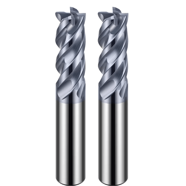
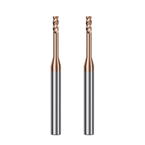
Why We Prioritize Carbide Micro End Mills
Ordinary high-speed steel micro end mills often experience edge wear or chipping after minutes of cutting small stainless steel parts. Ultra-fine grain carbide tools improve rigidity and increase tool life by over 30% under similar conditions. In a batch of medical micro-hole machining projects, replacing high-speed steel tools with carbide significantly improved dimensional consistency and surface roughness across production.
We do make trade-offs based on workpiece material and machining depth. Excessively hard or long carbide tools may induce vibration, reducing accuracy. Therefore, we consider both material and machining history from the micro end mills manufacturer when selecting the optimal tool.
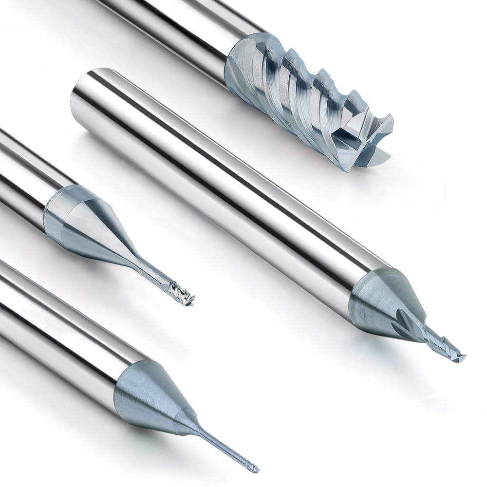
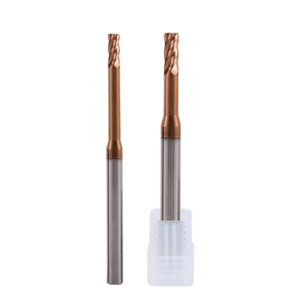
Micro Diameter End Mill Size Selection Strategy
Smaller tools are not always better. Tools with excessive length-to-diameter ratios (>5) lack rigidity, increasing bending and vibration, which leads to dimensional drift. We recommend ratios between 3 and 5 to balance rigidity and machining depth.
Workpiece material and cutting parameters also influence size selection. Aluminum can tolerate slightly larger diameters to improve chip removal, while stainless or hardened steel requires careful control of diameter-to-cut depth ratio to avoid stress on the tool. This approach ensures stable micro-diameter end milling with reduced risk of breakage.
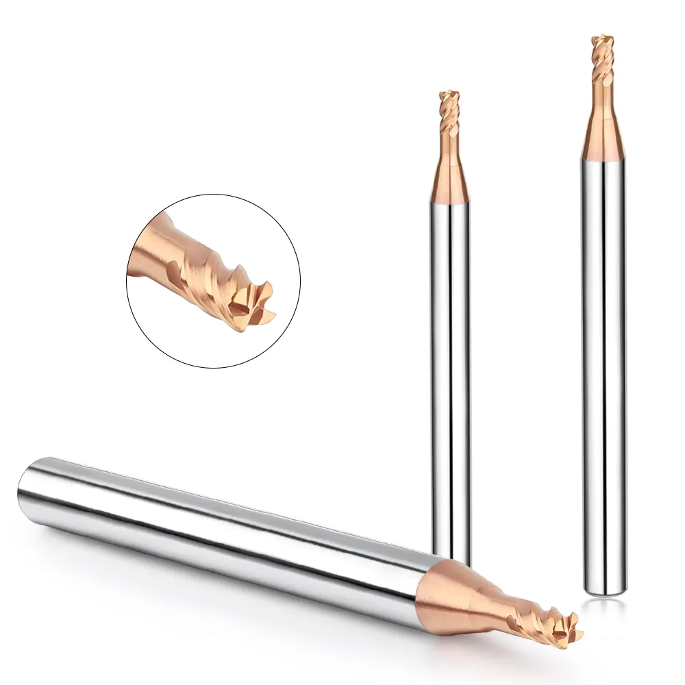
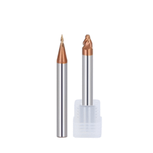
Application Experience of HRC58 Micro End Mills in Hardened Steel
Coating selection is often more critical than substrate. Inappropriate coatings accelerate wear or peeling, even on carbide tools. We observed TiAlN coatings outperform DLC in high-hardness steels, as DLC can peel locally after a few parts.
To avoid rapid wear, we reduce radial depth, control cutting speed moderately, and optimize tool paths to maintain stable stress on the HRC58 micro end mill. This significantly extends tool life while ensuring micron-level dimensional accuracy.
Flute Number Selection: 2-Flute vs 4-Flute
Material dictates flute choice. Aluminum and soft metals benefit from 4-flute tools for smoother surfaces, though chip evacuation is limited. Steel and hardened materials perform better with 2-flute tools to allow smooth chip evacuation and reduced heat.
Trade-offs are made based on material and depth of cut. We combine flute number, coating, and cutting parameters to maintain dimensional consistency during micro end milling.
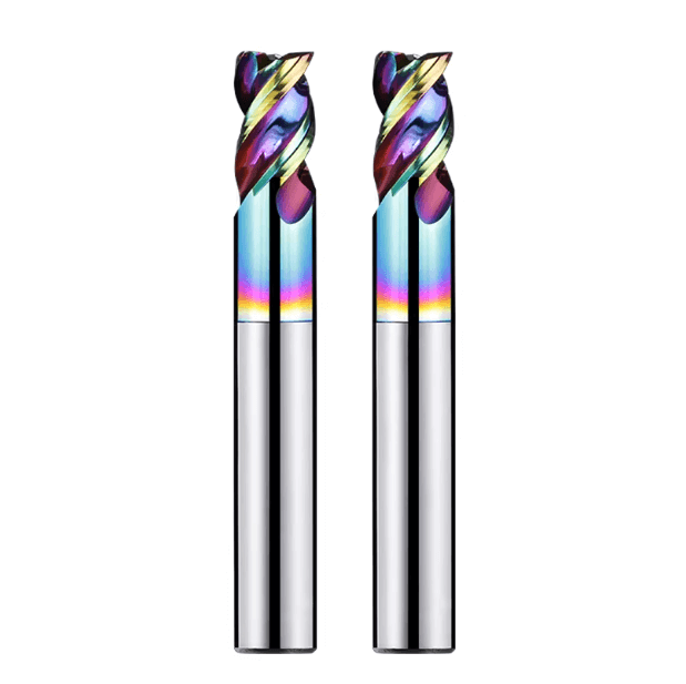
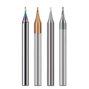
The Actual Impact of Tool Coatings on Micro-Milling Accuracy
Tool coatings significantly affect micro-milling accuracy, often underestimated. TiAlN vs DLC differences in thermal stability and wear resistance directly impact tool life and part dimensions. Improper coating selection can halve tool life and introduce dimensional deviations.
Selecting coatings requires considering material, cutting parameters, and machine performance. Thin coatings reduce resistance for aluminum at high speeds, while thick coatings provide wear resistance for hardened steel or titanium alloys. Proper coating enables carbide micro end mills to maintain stability and precision in micro-milling.

Micro End Mill Runout Control: Our Key Experience in Solving Accuracy Issues
In our micro-part machining projects, we’ve consistently found that even when tool material, cutting parameters, and machine conditions appear optimal, dimensional accuracy is difficult to maintain if runout is not properly controlled. Micro-diameter tools are extremely sensitive to even minor instability in the spindle and clamping system. A deviation of just a few micrometers at the tool holder can be amplified at the cutting edge, resulting in visible dimensional drift in hole diameters or surface features.
Because of this, we often emphasize to our clients that improving tool stability is more effective than simply selecting harder tool materials. In micro end milling, accuracy is not only determined by the tool itself, but by the entire system—tool holder, clamping condition, and machine rigidity.
In our practice, runout control is always treated as a priority. We evaluate the tool holder, chuck, tool extension, and machine condition as a complete system to ensure uniform cutting load and minimal vibration. This approach significantly improves dimensional consistency and surface finish, especially when machining stainless steel or hardened steel with micro-diameter tools. At the same time, it reduces the risk of tool chipping and burr formation.
Why We Control Runout to Within 3 μm
From on-site machining data, we have confirmed that even a runout of 2–3 μm can cause single-edge cutting when using micro-diameter tools. For example, when machining a φ0.3 mm hole, slight tool wobble can enlarge the hole diameter or create surface waviness. In continuous production, this leads to unstable part quality and frequent out-of-tolerance issues.
Based on repeated testing with our clients, we have found that keeping runout within 3 μm is a practical threshold for maintaining dimensional stability, especially when machining hardened steel or thin-walled parts.
We have also observed that excessive runout accelerates tool wear. Uneven cutting forces cause one edge to carry most of the load, leading to premature chipping. In several cases, simply optimizing the clamping method reduced dimensional variation from ±8 μm to ±2–3 μm without changing the tool itself.
This is why, in our experience, runout control is often more critical than tool material selection in micro end milling.
Tool Holder Selection: Heat Shrink vs. High-Precision ER Collets
In our operations, heat shrink tool holders provide clear advantages for micro-machining. Their uniform clamping force and high rigidity significantly reduce runout, especially for tools with a length-to-diameter ratio above 3. When machining hardened steel or stainless steel, we typically prefer heat shrink holders to maintain tool tip stability and consistent dimensions.
However, heat shrink is not always necessary. For low cutting loads, shallow features, or small-batch production, high-precision ER collet systems can be more practical. They allow faster tool changes and offer sufficient accuracy when properly maintained.
Our selection approach is straightforward: we consider material hardness, machining depth, and batch size. The goal is not to use the most expensive solution, but to achieve stable cutting conditions with the lowest risk.
Actual Testing Methods: How We Measure Runout in the Workshop
We have found that inaccurate measurement is a common issue in many workshops. Without proper measurement, it is difficult to identify the root cause of dimensional instability.
In our process, we use dial indicators or dedicated runout testers to measure both the tool tip and the collet area. It is important to ensure consistent contact force and correct measurement angles. Any deviation in measurement technique can lead to misleading results.
We also see common mistakes, such as measuring before full tightening or using low-resolution gauges. In several customer cases, tools assumed to be “high precision” actually had runout exceeding 5 μm. Only after standardized measurement did the real issue become clear.
For this reason, we recommend a quick runout check before each critical machining operation. This simple step can prevent many stability problems in micro-diameter end milling.
Customer Case: Resolving Tolerance Issues by Changing the Tool Holder
In one medical component project, the customer struggled with oversized hole diameters and inconsistent batch results. Initial adjustments to cutting parameters and tools did not resolve the issue.
After on-site inspection, we identified that the existing ER collet system, combined with tool holder wear, resulted in runout exceeding 5 μm. We recommended switching to a heat shrink holder and reducing tool extension.
After implementation, dimensional variation improved from ±7 μm to within ±2 μm, and surface finish also improved significantly.
This case reinforced an important point for us: even with the right tool and parameters, instability in the clamping system can dominate the final result. Runout control must always be part of the overall strategy in micro end milling.
Cutting Parameter Optimization: The Key to Avoiding Premature Tool Failure
In our experience supporting European and American clients, improper cutting parameters are one of the most common reasons for tool failure in micro-machining. Even with high-quality tools and stable clamping, incorrect parameter combinations can lead to immediate chipping or rapid wear.
Micro end milling requires precise coordination between spindle speed, feed rate, and depth of cut. Unlike standard machining, small deviations in parameter balance can significantly affect tool life and part accuracy.
Our approach is to start with machine capability and material properties, then combine tool geometry, coating, and overhang length to define initial parameters. We validate these parameters through small-batch trials, observing tool wear and dimensional variation before moving to full production.
This iterative process helps prevent early tool breakage and ensures consistent micron-level accuracy.
Matching Spindle Speed and Feed Rate (Real-World Experience)
We often see rapid tool wear when high spindle speed is combined with low feed rate. In this condition, the chip thickness becomes too small, and the tool tends to rub rather than cut, generating excessive heat.
On the other hand, low speed combined with high feed rate increases cutting force, which can easily break micro-tools, especially in deep cavities or hardened materials.
Our practice is to maintain a balance where the tool consistently cuts rather than rubs. For example, when machining hardened steel with a φ0.3 mm tool, we reduce radial engagement and carefully adjust feed per tooth to maintain stable chip formation.
This balance significantly improves both tool life and dimensional consistency.
Depth of Cut Control Strategy
Excessive radial depth of cut is one of the most common causes of tool breakage. Based on our field experience, we typically keep radial engagement between 5% and 20% of the tool diameter.
Axial depth is then adjusted based on material hardness and feature depth, usually using layered cutting to reduce load on the tool.
For thin-walled parts or hard materials, we further reduce tool overhang and optimize the toolpath to minimize vibration. This approach allows stable machining even with high aspect ratio tools.
How to Avoid Frictional Cutting
Frictional cutting is a frequent issue in micro-machining. It usually occurs when chip thickness is too small or parameters are not properly matched.
Symptoms include excessive heat, built-up edge, and poor surface finish. In severe cases, it leads to rapid tool wear or coating failure.
To avoid this, we ensure that the tool maintains effective cutting engagement. This involves adjusting feed rate and spindle speed to achieve proper chip thickness.
We also select appropriate coatings to reduce friction. For hardened steel, we often use TiAlN coatings combined with controlled cutting speed to maintain a stable temperature at the cutting edge.
Parameter Adjustment for Different Materials
Different materials respond very differently in micro-milling.
For stainless steel, built-up edge is a common issue. We reduce radial engagement, improve chip evacuation, and adjust feed to maintain stable cutting.
For aluminum, adhesion is the main problem. We increase cutting speed, use smoother toolpaths, and select coatings that reduce sticking.
For titanium alloys, heat accumulation is critical. We reduce cutting speed, use layered passes, and apply MQL or localized cooling to control temperature.
These parameter strategies are based on long-term observation of tool wear and dimensional variation across different materials.
Machine Tools and Workholding: The Most Overlooked Factors
No matter how well tools and parameters are optimized, machine performance and clamping stability often determine final part accuracy.
We frequently see cases where high-end tools are used on machines that cannot maintain the required rigidity. In such situations, achieving micron-level precision becomes extremely difficult.
Micro-vibration and spindle error are often underestimated. Even small deviations can be amplified when machining micro features, leading to poor surface finish and dimensional instability.
By improving machine setup and workholding, we can significantly enhance overall process stability.
Spindle Accuracy and High-Speed Performance
In micro end milling, we typically recommend spindle runout within 2–3 μm. If spindle deviation exceeds 5 μm, even high-quality tools cannot maintain dimensional consistency.
We have observed that upgrading to higher-speed, higher-precision spindles significantly improves tool life and machining stability, especially in hardened steel applications.
Before each project, we evaluate spindle performance and adjust cutting strategy accordingly.
Workpiece Clamping Rigidity
Clamping rigidity directly affects both tool life and part accuracy. Thin-walled parts are especially sensitive to micro-vibration, which can cause dimensional errors and poor surface finish.
In one project, increasing fixture support points reduced vibration by half, significantly improving machining stability.
Without proper clamping, adjustments to tools or parameters often have limited effect. We prioritize fixture design to ensure consistent force distribution during cutting.
How to Reduce Machining Vibration
We reduce vibration primarily by controlling tool overhang and optimizing toolpaths.
Excessive tool extension reduces rigidity and amplifies vibration. We keep overhang as short as possible while meeting machining requirements.
We also avoid sharp toolpath transitions and sudden load changes. Layered cutting and balanced cutting directions help maintain stable tool engagement.
Cooling Method Selection: Dry, MQL, or Coolant
Cooling strategy has a direct impact on tool life and accuracy.
Dry cutting is simple but often leads to overheating. Flood coolant can reduce temperature but may introduce instability in micro-machining.
In our experience, MQL provides the best balance. It reduces temperature while maintaining stable cutting conditions, especially for small-diameter tools and hard materials.
In comparative tests, MQL improved tool life by about 20% and reduced burr formation. This makes it our preferred method for most micro end milling applications.
Toolpath Strategy: The Core of Accuracy and Surface Quality
In our experience working with micro-machining projects, toolpath strategy often determines whether a part can actually meet tolerance—not the tool itself. We have seen many cases where the tool material and cutting parameters were technically correct, but poor toolpath planning caused vibration, localized overload, or chip packing. At the micron level, these issues immediately show up as dimensional drift or surface defects.
When we support customers, we usually start from the geometry of the part rather than the cutting data. Thin walls, deep micro-slots, and dense hole patterns all require different toolpath approaches. We then match the toolpath with tool rigidity and machine characteristics. This combination is what allows micro end milling to remain stable, especially when using tools in the 0.2–0.5 mm diameter range.
We also consistently see that toolpath design directly affects tool life. Sudden direction changes, sharp internal corners, and abrupt feed transitions create impact loads at the tool tip. With micro tools, even a small impact can lead to edge chipping. By smoothing the toolpath and controlling step-over and engagement, we can significantly reduce tool wear, improve surface finish, and maintain dimensional consistency across batches.
Climb Milling vs Conventional Milling in Micro Milling
In most of our projects, we prioritize climb milling. With micro-diameter end mills, climb milling produces a more stable cutting force because chip formation starts thick and becomes thinner. This reduces rubbing and minimizes force fluctuation at the cutting edge. In thin-wall machining and micro-feature finishing, this stability directly improves dimensional accuracy and surface quality.
That said, we do not treat climb milling as a fixed rule. In aluminum machining, for example, if the cutting edge is sharp and chip evacuation is smooth, conventional milling can sometimes produce a cleaner sidewall. When customers report built-up edge or surface tearing, we may test both strategies and compare surface roughness and burr formation. The final choice is always based on actual cutting behavior, not theory.
The Impact of Small Stepover on Surface Roughness
In medical and precision mold machining, step-over control is one of the key factors affecting surface quality. If the step-over is too large, scallop marks become visible, and secondary polishing is required. If it is too small, the tool remains engaged longer in the cut, increasing heat accumulation and accelerating edge wear. We typically recommend a step-over of 5%–10% of the tool diameter, depending on material and surface finish requirements.
We also combine step-over control with layered cutting strategies. Instead of removing all material in one pass, we distribute the cutting load evenly across multiple layers. This reduces peak cutting force, improves chip evacuation, and helps maintain a stable cutting temperature. In practice, this approach significantly reduces burr formation when machining micro medical parts and high-precision cavities.
Avoiding Sudden Stops and Sharp-Corner Paths
One of the most common causes of micro tool failure we see is sudden toolpath transitions. When the tool encounters a sharp corner or abrupt stop, the instantaneous load increases significantly. With micro end mills, this often leads to edge chipping or micro fractures that are not immediately visible but will affect subsequent machining accuracy.
To avoid this, we design toolpaths with smooth transitions and continuous engagement whenever possible. Corner rounding, spline interpolation, and constant engagement strategies all help reduce impact loads. We also simulate toolpaths to identify high-load zones before actual machining. Even with high-quality carbide tools, poor path design will shorten tool life and reduce process stability.
Application of High-Speed Machining (HSM) in Micro End Milling
In our experience, high-speed machining can be very effective in micro-milling, but only when the system is rigid enough. With a high-precision spindle, stable tool holding, and short tool overhang, HSM helps reduce cutting force per tooth and improves surface finish. We often apply HSM strategies when machining aluminum alloys and certain titanium components to stabilize the cutting process.
However, HSM is not universally applicable. In thin-wall structures or high-hardness materials, insufficient machine rigidity or unstable clamping can lead to vibration and dimensional drift. We have seen cases where increasing spindle speed actually worsened surface quality. Our approach is to validate machine capability first, then gradually increase speed while monitoring vibration, tool wear, and part accuracy.
Tool Wear and Replacement Strategy (Directly Affecting Accuracy Stability)
In micro-milling, tool wear is one of the most common causes of dimensional instability. Even when all other conditions are optimized, wear at the cutting edge will gradually change the effective tool diameter and cutting behavior. For micron-level tolerances, this change becomes visible very quickly.
In our projects with medical and precision mold customers, we treat tool condition monitoring as a standard part of the process rather than an afterthought. By tracking wear progression and correlating it with part quality, we can maintain consistent performance throughout batch production. This is especially important when machining features that require tight tolerances and stable surface finish.
How We Determine When to Replace Micro Tools
We do not wait for tools to break before replacing them. In micro-milling, breakage is usually the final stage of failure, not the first signal. The earliest indicator is dimensional drift. If part dimensions begin to shift consistently in one direction, we immediately check tool condition.
We also monitor surface finish and cutting sound. A slight increase in cutting noise or a change in chip color can indicate edge wear or heat accumulation. When machining hardened materials, even minimal edge wear can push the part out of tolerance. Replacing the tool earlier helps maintain consistency and prevents scrap in batch production.
Common Wear Forms and Their Causes
From our experience, micro end mills typically exhibit three types of wear: edge chipping, edge rounding, and coating delamination. Edge chipping is usually caused by impact loads or excessive feed per tooth. Edge rounding occurs gradually due to heat and friction, especially when chip thickness is too low. Coating delamination is often related to high cutting temperature or incompatible cooling strategies.
We analyze worn tools under magnification to identify the dominant wear mechanism. This allows us to adjust parameters accordingly. For example, when machining stainless steel micro-features, reducing radial engagement and improving chip evacuation often reduces edge rounding and extends tool life. Each wear pattern provides feedback for process optimization.
Experience in Establishing a Tool Life Database
For many of our European and U.S. customers, we recommend building a tool life database. This includes tool diameter, coating type, material, cutting parameters, and the number of parts machined per tool. Over time, this data provides a reliable reference for predicting tool life under specific conditions.
We have seen that shops with structured tool life data achieve much better consistency. Instead of reacting to tool failure, they can plan replacement intervals and maintain stable production. This is particularly useful in micro-milling, where tool behavior can change significantly with small variations in parameters or material properties.
Preventive Replacement Strategy
In most of our projects, we implement preventive tool replacement rather than reactive replacement. For micro tools, waiting until wear becomes visible often means that several parts have already gone out of tolerance. Preventive replacement helps maintain consistency across the entire batch.
As a general guideline, we replace tools when they reach about 50%–60% of their expected life, depending on material and cutting conditions. For example, when using 0.2–0.3 mm carbide tools, this strategy significantly reduces unexpected breakage and improves dimensional stability. The exact threshold is always adjusted based on actual cutting performance.

Real-World Optimization Cases from Customer Sites
Over the years, we have learned that theoretical optimization is only the starting point. Real stability comes from validation on the machine. Many of our improvements come from on-site testing, where we adjust parameters, tool selection, and toolpath based on actual cutting behavior.
Different materials and geometries respond differently to the same setup. By working closely with customers and recording machining data, we have developed repeatable approaches for micro-milling in medical, mold, and precision electronics applications. These methods focus on stability, not just initial performance.
Medical Parts: Controlling Burrs Within 5 μm
In one medical component project, we encountered burrs exceeding 10 μm at micro-hole edges. By adjusting radial engagement to below 10% of tool diameter and switching to climb milling, we reduced cutting force and improved chip evacuation. We also selected ultra-fine grain carbide tools to increase edge stability.
Additionally, we implemented minimum quantity lubrication (MQL) to control cutting temperature. This reduced edge chipping and improved surface integrity. After optimization, burr height was consistently controlled within 5 μm, and batch consistency improved significantly.
Mold Machining: Improving Accuracy in HRC58 Material
When machining hardened steel at HRC58, we found that tool wear and toolpath design were the main factors affecting accuracy. By selecting appropriate coated micro end mills and reducing radial engagement, we achieved more stable cutting conditions.
We also optimized the toolpath to ensure smooth transitions in corners and thin-wall areas. As a result, dimensional tolerance improved from ±10 μm to ±5 μm, while tool life increased. This combination of tool selection and path optimization proved to be more effective than adjusting parameters alone.
Precision Electronic Components: Achieving ±3 μm Tolerance
For precision electronic components, achieving ±3 μm tolerance requires control over the entire process. We evaluate machine spindle accuracy, tool holding, and tool length before setting cutting parameters. Every factor must be within a stable range.
During machining, we monitor part dimensions and adjust cutting conditions if needed. By controlling heat buildup and minimizing vibration, we maintain consistent accuracy. This approach has allowed us to achieve stable micron-level tolerances in batch production.
Quality Changes After Switching Micro End Mill Manufacturers
We have seen multiple cases where changing the tool supplier significantly improved machining stability. Differences in tool geometry, coating consistency, and edge quality can have a major impact in micro-milling.
In one case, after switching tools, dimensional consistency improved by 2–3 times, and burr formation decreased noticeably. This reinforced our view that consistency is more important than maximum hardness or aggressive cutting capability. Stable tools make stable processes.

Key Lessons Learned from Our Projects
Through years of micro-milling projects, we have learned that stable dimensional accuracy and surface quality cannot be guaranteed solely by tool material or machine parameters. Micro-diameter tools are extremely sensitive to spindle rigidity, clamping systems, cutting parameters, and toolpath strategies, especially when machining high-hardness materials, thin-walled components, or complex geometries. From these experiences, we have summarized several key lessons that can guide you in optimizing your own machining conditions.
These lessons highlight that micro-milling optimization is a systemic process rather than a single-point adjustment. Even with high-quality carbide micro end mills, insufficient runout control or improper cutting parameters can lead to dimensional drift, burrs, or premature tool wear. By considering tool selection, machine conditions, tool holders, fixtures, cutting parameters, and toolpath strategies together, we have consistently achieved stability and repeatable results in micron-level part machining at multiple customer sites. If you are working on similar micro-milled parts, you can verify and optimize each factor while taking your machine’s rigidity and material properties into account.
Accuracy Issues Are Usually Not Caused by a Single Factor
In most real-world projects, dimensional drift or surface defects are rarely caused by a single factor. They are usually the result of combined effects from tool rigidity, cutting parameters, and clamping stability. For instance, when machining micro-diameter parts in stainless steel or HRC58 hardened steel, even using an appropriate tool material, excessive tool extension or spindle runout can cause out-of-tolerance holes.
If you are experiencing significant dimensional fluctuations, review the entire machining system: the tool, tool holder, clamping setup, machine rigidity, and cutting parameters. Systematic troubleshooting and optimization are the only reliable ways to stabilize micro-milling accuracy. You can also discuss specific working conditions, drawings, or materials with us to analyze potential issues together.
Tools, Machine Tools, and Parameters Must Be Optimized Simultaneously
Experience shows that tool selection, machine tool performance, and cutting parameters must be optimized together; adjusting only one factor rarely guarantees accuracy. For example, with micro-diameter tools on high-hardness steel, excessive radial depth of cut or mismatched spindle speed and feed rate can cause tool tip chipping, even if the tool itself is highly rigid. Similarly, machine spindle vibration can lead to dimensional drift if not addressed.
If you are trying to improve micro-milled part accuracy, check the tool material, coating, tool holder rigidity, and cutting parameters simultaneously. Comprehensive adjustments based on spindle accuracy and machine rigidity have allowed us to consistently achieve ±2–3 μm dimensional consistency across multiple customer sites. You can provide your specific machining conditions, and we can discuss targeted optimization solutions.
Controlling Runout Is More Important Than Replacing Tools
We have observed that for micro-diameter tools, runout control has a greater impact on accuracy than simply replacing the tool. Even small runouts amplify tool vibration, creating single-edge cutting and larger dimensional deviations. Even a brand-new, high-rigidity HRC58 micro end mill cannot achieve stable results if the tool holder or chuck is unstable.
If you face dimensional drift or short tool life, prioritize checking and optimizing tool runout. Measures include using heat-shrink tool holders or precision flexible collets, shortening tool extension, and optimizing toolpaths. You can share your part dimensions, materials, and machine conditions with us, and we can analyze the impact of runout and propose improvements.
Stability Is More Critical Than Single-Batch Accuracy
The ultimate goal of micro-milling is not only individual part accuracy but also batch-to-batch stability. Achieving micron-level precision on a single part is insufficient if subsequent parts are inconsistent. In our projects with medical devices, molds, and precision electronics, we emphasize overall machining stability through tool life management, optimized cutting parameters, and improved machine and fixture rigidity.
If you are focused on single-batch accuracy, consider establishing tool life records, refining cutting processes, and optimizing machining sequences to ensure consistency across batches. We can discuss specific strategies based on your drawings, materials, and production volumes, helping you translate single-part accuracy into reliable, repeatable production results.