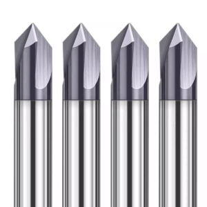
In our projects machining high-precision parts in batches for European and American clients, we frequently encounter a seemingly simple yet recurring problem—the chamfered edges fail to achieve the desired “perfect” state. Whether we are using a chamfer end mill cutter for rapid chamfering on aluminum alloy parts or a 45-degree chamfer end mill for assembly edge treatment of precision stainless steel parts, we notice that the same tool performs significantly differently across different machine tools, materials, and even batches of parts.
Through repeated on-site tests with a corner chamfer end mill and standard chamfering cutters, we observed that even slight differences in tool selection, cutting parameters, machine rigidity, and clamping methods can lead to problems such as burrs, chipping, or unstable edge dimensions. Although carbide tools from our trusted carbide chamfer end mill supplier provide excellent wear resistance, achieving the precision and surface quality required by customers is impossible if the machining strategy is not properly matched.
Over time, we realized that a “perfect chamfer” is not achieved solely by the cutting tool. Instead, it results from a systematic alignment of the tool, machine tool, material, and cutting parameters. Each chamfering failure indicates that one or more aspects of the process have not been fully considered.
So, how do we choose the right chamfer end mill for different materials, machine models, and complex part structures, ensuring consistent edge quality while maintaining efficiency?

How Do We Define a “Perfect Chamfer Edge” in Actual Machining?
Over many years of machining high-precision parts, our definition of a “perfect chamfer edge” has evolved beyond simply achieving a smooth appearance. Today, it is a comprehensive standard combining customer assembly and usage requirements. We often work with aluminum alloys, hardened steel, and precision stainless steel components. Each material presents unique challenges, including burr formation, micro-chipping, or slight dimensional deviations during cutting.
By comparing the actual performance of different chamfer end mill cutters, we have found that edge quality depends not only on tool selection but also on machine rigidity, fixture stability, and fine-tuning of cutting parameters. Even the same 45-degree chamfer end mill may produce very different results across machine tools and batches. This led us to understand that achieving a perfect chamfer is a process of continuous adjustment based on practical experience. On-site, we adjust tool type, depth of cut, feed rate, and coolant strategy in real time to meet assembly accuracy and surface quality requirements for each workpiece.
Most Common Chamfering Quality Requirements from Customers (No Burrs, No Chipping, Consistent Dimensions)
When machining high-precision parts for European and American clients, the most frequently emphasized requirements are no burrs, no chipping, and consistent chamfer dimensions. For instance, in aerospace or medical device parts, even burrs of a few hundred micrometers can compromise assembly or downstream processing.
We prioritize using a corner chamfer end mill for corner chamfered areas to avoid chipping caused by tool interference. Additionally, we determine optimal cutting speed and feed rate through actual testing. Maintaining consistent chamfer dimensions across multiple stations is often overlooked but critical. Experience allows us to monitor tool wear and fine-tune tool offsets or parameters, ensuring that edges across each batch remain within customer-accepted tolerances.
Differences in Edge Quality Requirements Across Application Scenarios (Assemblies vs. Exterior Parts)
The intended use of the part directly affects chamfering priorities. For assembly components, dimensional accuracy and edge position consistency outweigh surface finish. For exterior parts, smoothness and surface quality may take precedence over strict dimensional tolerances.
Based on this, we select more wear-resistant carbide chamfer end mills for assemblies and strictly control cutting parameters to maintain dimensional accuracy. For exterior parts, we may use finely tuned chamfer end mill cutters at lower speeds to reduce burrs and cutting marks. This trade-off frequently occurs in practice; for example, slight chamfer dimensional deviations may be acceptable on aluminum panels for painting, but edge smoothness must remain burr-free. These judgments are informed by years of hands-on experience, allowing us to make rapid, practical decisions.
Why Does the Same Chamfer End Mill Perform So Differently on Different Machine Tools?
One common issue in long-term field support is that the same 45-degree chamfer end mill can behave very differently on separate machine tools. Differences in rigidity, spindle vibration, tool holder accuracy, and fixture stability often cause minor chipping or burrs.
We reassess cutting parameters for each machine and adjust fixtures or tool holders as needed to ensure edge quality meets expectations. Material properties also play a significant role: on stainless steel, slight runout may tear edges, while on aluminum, it can create brush marks. By combining practical experience with careful adjustment of tool selection, cutting parameters, and feed paths, we achieve consistent chamfered edges across machines, rather than relying solely on tool brand or specifications.
Key Factors Affecting Chamfer Quality
From hundreds of on-site projects, we have categorized the key factors affecting chamfer stability into five areas: tool type, angle selection, cutting edge sharpness, machine and clamping rigidity, and material properties. Even the same chamfer end mill may produce burrs or inconsistent edges if these factors are not properly balanced.
In practice, we quickly determine which tool and cutting strategy suit the workpiece. Customers often face interference or chipping when machining corners with standard chamfering cutters, reminding us to consider actual part geometry and machine capabilities. Fine-tuning corner chamfer end mills for complex positions ensures edge stability and dimensional consistency.
Common Problems Caused by Incorrect Tool Type Selection (Corner Chamfer End Mill vs Standard Chamfering Cutter)
Many customers still use standard chamfer end mill cutters for corners or deep cavities, leading to chipping or tool interference. In our field experience, standard cutters often fail to reach corners due to insufficient cutting length or unsuitable tip geometry, causing burrs or minor tool damage.
We select corner chamfer end mills based on part geometry and machining space. For multi-faceted chamfers or tight corners, this ensures stable results. However, machine rigidity and clamping must support the tool; otherwise, vibration or chipping persists. On-site, we weigh tool life, machining efficiency, and edge quality, making informed trade-offs.
Limitations of the 45-Degree Chamfer End Mill in Practical Applications
While effective for most assemblies, a 45-degree chamfer end mill has limitations on thick-walled stainless steel or complex geometries. High-speed cutting can cause burring or micro-chipping, leading to inconsistent edge dimensions. We mitigate this by reducing feed rate and depth of cut, balancing tool life and efficiency.
In deep cavities or interference-prone positions, the 45-degree tool may have limited tip contact, requiring a corner chamfer end mill for interference-free chamfering. Decisions depend on part structure, efficiency, and edge quality trade-offs.
The Impact of Chamfer End Mill Cutter Edge Sharpness on Edge Quality
Even slight differences in edge sharpness can affect chamfer quality. Sharp tools produce virtually burr-free aluminum cuts, but wear in long batches creates rough edges. We regularly monitor sharpness and replace or regrind tools to maintain consistency.
In stainless steel or high-hardness materials, dull edges increase tearing risk. We combine adjusted cutting parameters and cooling strategies to delay wear, but experience shows edge sharpness is a primary determinant of chamfer quality.
The Impact of Machine Tool Rigidity and Clamping Method on Chamfer Stability
Even with proper tools and parameters, insufficient machine rigidity or unstable clamping causes burrs and minor chipping. In one aerospace project, the same 45-degree chamfer end mill produced severe edge chipping on one machine but nearly perfect edges on another.
We adjust cutting strategies to match machine characteristics—reducing depth, lowering feed rate, or improving fixture stability. Rigidity often determines chamfer quality more than theoretical parameters, making it the first factor we assess when troubleshooting on-site.
Practical Challenges Arising from Material Differences (Aluminum, Stainless Steel, Hardened Steel)
Material significantly impacts chamfer quality. Sharp tools and fast feed rates on aluminum can cause wire drawing; stainless steel may tear edges or form burrs; high-hardness steel accelerates tool wear and chipping. We select chamfer end mill cutters, cutting parameters, and cooling strategies based on material characteristics.
We also advise batch testing different tools and parameters for high-hardness or irregularly shaped materials. This approach balances tool life, efficiency, and edge quality, allowing us to find the most suitable machining solution.

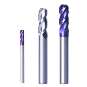
Our Experience in Choosing the Right Chamfer End Mill
Through years of on-site machining, we’ve found that selecting the right chamfering tool often has a greater impact on edge quality than simply optimizing cutting parameters. We handle a wide range of parts—from aluminum alloys to high-hardness steel components—each requiring different considerations for tool rigidity, cutting edge geometry, and wear resistance. We base our tool selection on part shape, chamfer angle, batch size, and machine capabilities to ensure edge quality and tool life remain within acceptable limits.
Tool selection also directly affects production efficiency. Inconsistent tool life or edge quality complaints are frequently reported by customers. We manage these issues by carefully choosing tool type, cutting edge design, and appropriate feed and cooling strategies. Experience has shown us that understanding how each tool performs on different materials and machines is more reliable than relying solely on manufacturer specifications.
When Must a Corner Chamfer End Mill Be Used?
In practice, using a standard chamfer end mill cutter can lead to interference or edge chipping, especially on parts with complex corners or deep cavities. For instance, while machining a batch of aerospace components, we observed continuous chipping when using a standard chamfering tool in internal corners. Switching to a corner chamfer end mill and adjusting the cutting path eliminated interference and maintained consistent edge dimensions.
Before programming or machining, we evaluate part geometry and available surface space. If a chamfer is close to a fixture or there is interference risk, we prioritize corner chamfer end mills. While slightly more expensive, they reduce rework and improve edge quality, offering better overall value. We balance tool safety and machining efficiency depending on specific project conditions.
Advantages and Risks of a 45-Degree Chamfer End Mill in Batch Machining
For high-volume machining, a 45-degree chamfer end mill is often our go-to tool. Its moderate tip angle balances cutting speed with edge quality, making it effective on aluminum alloys and low-hardness steels. By optimizing cutting parameters, we have achieved efficient, consistent chamfering across batches of precision assemblies.
However, 45-degree tools have limitations in deep cavities, tight internal angles, or high-hardness materials. High-speed cutting can cause minor edge chipping, wire drawing, or slight dimensional deviations. We mitigate these risks by reducing feed rates, performing multiple light cuts, or adjusting toolpaths—trading slight efficiency for consistent edge quality.
How to Determine if a Custom Chamfer End Mill Cutter is Needed
Some parts with complex geometry or non-standard chamfer angles cannot achieve required accuracy with standard chamfer end mill cutters. We assess tool suitability by measuring cutting edge length, angle, and diameter on-site, sometimes performing simulated cuts. If interference or dimensional deviations occur, we consider custom tools.
Although custom tools cost more, they substantially improve edge quality and tool life. We discuss machining requirements and costs with clients, ensuring cutting edge geometry, material, and coating are suitable for the actual machining environment, maximizing tool utilization efficiency.
Why We Recommend Carbide Chamfer End Mills
In long-term experience, carbide chamfer end mills outperform high-speed steel (HSS) tools in wear resistance and edge stability. For example, machining stainless steel components with a carbide chamfer end mill maintains sharp edges over hundreds of pieces, whereas HSS tools may produce burrs and chipping after a dozen pieces.
We consider material, chamfer depth, and machine rigidity when choosing carbide. For light aluminum or non-critical chamfers, HSS may suffice. For high-hardness or precision-critical parts, carbide is almost always preferred, a conclusion repeatedly validated in field experience.
How to Select a Reliable Carbide Chamfer End Mill Supplier
We have worked with many suppliers and observed wide performance differences among carbide chamfer end mills. We request samples for on-site testing, evaluating edge quality, burr formation, and tool wear before committing to long-term cooperation.
Supply chain stability and batch consistency are critical. On one occasion, a client received two consecutive batches of tools with drastically different performance, causing inconsistent chamfer quality. Establishing a partnership with a reliable supplier, combined with on-site testing and tool management systems, ensures consistent, controllable edge quality. This reinforces that supplier selection should consider both quality and stability, not just price.
How Machining Parameters Directly Determine Chamfer Quality
Edge quality is rarely determined by the tool alone. In our experience, cutting parameters and material properties are equally critical. The same chamfer end mill cutter can behave very differently under different spindle speeds, feed rates, or cooling strategies. Minor adjustments can eliminate burrs or worsen chipping, especially in batch machining of aluminum or stainless steel parts.
Machine spindle characteristics, clamping stability, and coolant methods also affect forces on the tool, altering edge quality. On-site, we develop customized spindle speed, feed, and depth of cut plans based on tool geometry, material hardness, and workpiece shape, rather than relying on standard tables. Experience shows that parameter optimization and on-site verification are key to consistent chamfering.
Our Commonly Used Spindle Speed and Feed Rate Settings (Actual Measured Data for Different Materials)
For aluminum, we use higher spindle speeds with medium feed rates to fully utilize the cutting efficiency of a 45-degree chamfer end mill while avoiding burrs or wire drawing. For stainless steel, spindle speed and feed are reduced to control temperature and minimize edge chipping. On-site measurements showed that a 10% increase in feed rate increased average burr length by ~0.05 mm, emphasizing the need for careful tuning.
For high-hardness steel, we use multiple shallow cuts, medium spindle speed, and reduced feed to avoid tool overload. We maintain an empirical database to quickly determine initial parameters while retaining fine-tuning flexibility for stable edge quality.
Real-World Case of Edge Chipping Caused by Excessive Feed Rate
While machining aluminum frame parts, using a standard feed rate initially caused significant edge chipping. Analysis revealed slight tool vibration during cutting, exacerbated by aluminum’s softness. Reducing feed by ~15% and slightly increasing cut passes immediately improved edge quality.
This case reinforced that even with proper tool selection and machine setup, excessive feed rate directly affects chamfer edges. We now always start with conservative feed rates and optimize based on material and machine conditions.
Analysis of Tool Vibration Caused by Excessive Depth of Cut
In machining high-hardness steel, a deep chamfer in a single pass with a corner chamfer end mill caused significant vibration, micro-chipping, and dimensional instability. Excessive depth of cut created uneven tool stress, amplified by limited machine rigidity, affecting edge quality.
We mitigate this by using multiple shallow cuts, balancing efficiency with edge consistency. Step-by-step chamfering is now standard for complex parts to ensure quality.
Comparison of the Actual Effects of Dry Cutting and Coolant on Different Materials
Dry cutting and coolant use significantly affect edge quality. For aluminum, dry cutting reduces burrs but can leave wire-like marks; appropriate coolant improves surface finish, but poor flow or spray angle can still cause micro-chipping.
For stainless steel and hardened steel, coolant is critical. Dry cutting with carbide end mills raises tool temperature quickly, accelerating edge wear and causing tearing. High-pressure cooling combined with controlled feed maintains stable edge temperature and consistent chamfer quality.
How to Eliminate Burrs Through Fine-Tuning Parameters (On-Site Machine Adjustment Experience)
We often eliminate burrs or reduce chipping by adjusting spindle speed, feed, depth, and toolpath. On aluminum, minor burrs are addressed by reducing feed and increasing toolpath overlap; on stainless steel, increasing coolant flow and reducing cut depth smooths edges.
These adjustments consider tool type, machine rigidity, and material. We document each fine-tuning effect on-site, creating a reference database for future batch machining. Long-term experience shows subtle on-site parameter adjustments are often more effective than changing the tool alone.

Practical Techniques for Avoiding Burrs and Chipping
In our years of on-site machining experience, burrs and chipping are the most common problems during chamfering. Material type and workpiece geometry significantly affect chamfering stability. We have found that relying solely on tool type or tool tip geometry is rarely sufficient to ensure edge quality. A comprehensive approach—including cutting parameters, cutting sequence, clamping methods, and cooling strategy—is necessary. Through long-term practice, we have developed practical techniques applicable to various materials and chamfer angles, effectively reducing edge defects.
At the same time, we often discuss the trade-off between tool life and machining efficiency with our clients on-site. Improper handling of burrs and chipping can directly impact subsequent assembly or surface treatments. Therefore, we emphasize not only selecting the right chamfer end mill cutter but also combining on-site fine-tuning and tool monitoring to ensure edge consistency and stability for each batch of parts.
Methods for Handling Burrs Easily Formed During Chamfering of Aluminum Parts
Aluminum alloys, particularly thin-walled or complex geometries, are prone to minor burrs. We typically start by selecting a sharp 45-degree chamfer end mill, slightly reducing the feed rate and moderately increasing toolpath overlap to achieve smoother cutting. Our on-site experience shows this approach significantly reduces burr formation without compromising machining efficiency.
We also monitor the tool-workpiece contact angle to prevent the cutting edge from scraping against sidewalls. If minor burrs appear, we slightly increase the cutting margin or adjust the tool offset without changing overall parameters. Using this method, we can virtually eliminate burr issues in high-volume aluminum chamfering.
Solution for Tearing Edges in Stainless Steel Chamfering
Stainless steel parts often experience tearing or minor edge chipping, especially during high-speed cutting or when the tool is slightly worn. We typically reduce the feed rate and increase coolant flow to maintain cutting edge temperature within a safe range, reducing edge wear and improving edge stability.
For complex corners, we employ a corner chamfer end mill combined with a multi-pass shallow cutting strategy to avoid excessive force in a single pass. On-site, we find that tearing results from a combination of tool, material, and parameters, requiring careful fine-tuning based on specific circumstances.
Chipping Control Techniques for High-Hardness Materials (HRC50+)
High-hardness steel or hardened steel (HRC50+) increases the risk of edge chipping. Single deep cuts or high feed rates easily cause micro-chipping. Our standard practice involves multi-stage shallow cuts, removing only 0.1–0.2 mm per pass, while maintaining sharp tools and rigid clamping to minimize chipping.
Coolant flow and cutting path optimization are also critical. We aim for continuous cutting, uniform tool force, and minimal vibration or thermal deformation, monitoring tool wear throughout. While this approach slightly reduces machining speed, it significantly improves edge quality and batch consistency.
When Must the Tool Be Replaced (Experience-Based Criteria)
We do not rely solely on the number of processed batches to determine tool replacement. Instead, we observe edge quality and tool condition. When minor burrs appear, chipping frequency increases, or dimensional deviations exceed tolerances, it signals that the tool should be replaced or reground. Slight dulling of chamfer end mill cutters may manifest as wire drawing on aluminum and tearing edges on stainless steel.
On-site, we track tool usage, material type, and batch parameters, combining this data with experience to decide on replacement. Keeping tools sharp ensures edge quality and extends the overall lifespan of the batch, preventing rework or scrap due to cutting edge issues.
Is a Secondary Chamfering or Light Tool Rest Strategy Necessary?
For high-precision parts, a single chamfering pass may not eliminate minor burrs or chipping. In such cases, we use secondary chamfering or light finishing. A 45-degree chamfer end mill or small-diameter corner chamfer end mill performs micro-cuts to locally correct edges, ensuring chamfer dimensions and surface smoothness.
The necessity of secondary chamfering depends on material, chamfer area, and batch size. For aluminum or low-hardness steel, a single pass with fine-tuning is often sufficient. For high-hardness or complex internal corners, secondary chamfering is usually essential to maintain assembly accuracy and surface quality. On-site judgment guides this decision rather than a fixed process.

Practical Solutions for Chamfering Complex Workpieces
Chamfering complex parts is often the most challenging aspect of tool selection and machining strategy. These workpieces frequently have deep cavities, interference zones, or multi-faceted chamfer requirements, making standard cutting solutions inadequate. We have found that combining a corner chamfer end mill with careful toolpath planning is the most effective way to improve machining efficiency and batch consistency while maintaining edge quality.
Our experience shows that chamfering complex workpieces requires more than just assessing tool or machine capabilities. Material properties, machine rigidity, tool sharpness, and cooling strategies must all be evaluated. Small-batch trial cuts are typically performed before formal machining to verify tool performance in deep cavities and multi-faceted chamfers, reducing the risk of rework.
How to Use a Corner Chamfer End Mill for Deep Cavities and Interference Locations
Parts with deep internal cavities or compact structures can cause tool interference or edge chipping when using standard chamfering tools. A corner chamfer end mill is essential in these scenarios. We select a tool with an appropriate diameter and cutting edge length and adjust the cutting sequence to ensure smooth corner entry without contacting fixtures or sidewalls.
In one aerospace project, repeated attempts with a standard chamfering tool caused consistent edge chipping. By switching to a small-diameter corner chamfer end mill and modifying the toolpath, we successfully completed the deep cavity chamfering. Prioritizing tool rigidity and cutting path assessment, along with reducing feed and depth of cut, ensures stable edges without relying on a single deep cut.
Experience tip: Always simulate deep cavity toolpaths before full production to minimize edge defects.
How to Ensure Dimensional Consistency in Multi-Face Chamfering
Multi-faceted chamfering requires consistent edge dimensions on every face, which is more complex than single-facet chamfering. Our approach is to first develop a unified toolpath and cutting parameters based on part clamping and machine characteristics. Fine-tuning tool offsets or using multiple shallow cuts ensures uniform dimensions and edge quality.
Even with the same chamfer end mill cutter, differences can occur between stations or chamfered faces. Sample tests and recording tool wear and parameter changes generate empirical data for rapid adjustments, maintaining edge consistency in batch machining.
Practice insight: Creating a standardized toolpath and monitoring wear data is crucial for multi-faceted chamfer control.
Differences in Chamfering Between 5-Axis and 3-Axis Machine Tools
3-axis machines are limited in tool force direction, making complex corners and deep cavities prone to vibration and burrs. 5-axis machines can tilt or rotate the tool, reducing interference and improving edge quality.
On a batch of aerospace parts, multi-faceted chamfering on a 5-axis machine achieved stable edges with minimal burrs. The same parts on a 3-axis machine required multiple toolpath adjustments and depth/feed control to reach acceptable quality. Machining method selection should consider part geometry, batch size, and available machine tools, not just machine type.
Field insight: Proper axis selection can reduce rework and ensure consistent chamfer quality.
How to Reduce Repetitive Machining Through Toolpath Optimization
Rework or repeated chamfering often stems from poor toolpath design. Optimizing the chamfer end mill cutter path includes adjusting cutting sequence, minimizing idle cuts, increasing toolpath overlap, and using shallow cuts to reduce vibration and burrs.
Simulation and small-batch trials help verify toolpaths before mass production. Correct planning ensures efficient, safe cuts, reduces secondary chamfering, and maintains edge consistency.
Experience note: A well-optimized toolpath improves both edge quality and overall machining efficiency.

The Most Common Chamfering Problems We Encounter at Customer Sites
Through years of on-site support for European and American customers, common problems include inconsistent dimensions, burrs or chipping, edge blackening, and unstable tool life. Even with the same chamfer end mill cutter, variations in part batches, machines, fixtures, or materials can produce different edge results. On-site judgment and rapid adjustments are essential to maintain chamfering quality.
Most issues are multifactorial: tool, machine, and parameters combined. Inconsistent dimensions often occur with burrs; edge blackening is often caused by speed or coolant issues; abnormal tool wear may result from material hardness, machine vibration, or supplier batch differences. Rapid root-cause analysis and on-site fine-tuning are critical.
Root Cause Analysis of Inconsistent Chamfer Dimensions
Inconsistent chamfer dimensions often arise from uneven tool wear or unstable machine clamping. For example, after machining dozens of aluminum parts with a 45-degree chamfer end mill, slight edge wear caused minor deviations that could exceed assembly tolerances.
Other causes include insufficient machine rigidity, tool holder accuracy deviations, or loose clamps. Small-scale testing, tool monitoring, and parameter adjustments ensure consistent chamfer dimensions during mass production.
Engineering insight: Track tool wear continuously for multi-batch consistency.
Causes of Edge Blackening or Burning
High-speed cutting or insufficient coolant can cause blackening or burning, especially in hardened steel. Even highly wear-resistant carbide chamfer end mills may overheat if heat dissipation is inadequate.
Edge temperature can be controlled by reducing spindle speed, increasing coolant flow, or performing multiple shallow cuts. Though slightly increasing machining time, this approach significantly improves chamfer stability and surface quality.
Best practice: Prioritize thermal control when machining high-hardness materials.
Typical Scenarios of Abnormal Tool Wear
Abnormal tool wear often occurs with high-hardness materials, large batches, or uneven tool stress. Excessive depth of cut or feed rate can cause micro-cracks or chipping, increasing burrs.
Material inhomogeneities can accelerate wear. Recording usage, edge quality, and dimensional changes helps determine early replacement, ensuring machining efficiency and avoiding batch defects.
Pro tip: Regular monitoring prevents unplanned rework and maintains batch quality.
Why There Is a Large Performance Variation Among Tools in the Same Batch (Supplier Issue)
Even identical carbide chamfer end mill models can vary significantly across batches or suppliers. Some tools remain sharp after dozens of parts; others may chip after only a few, directly affecting chamfer consistency.
We conduct sample tests, combining cutting performance and tool life data, to select reliable suppliers. Specifications alone are insufficient; batch stability and actual performance are key to maintaining consistent edge quality in batch machining.
Experience insight: Supplier verification and on-site testing are critical for consistent chamfer performance.

Experience Summary on Improving Chamfering Efficiency and Stability
In our long-term on-site machining practice, successful chamfering requires not only stable edge quality but also consistent machining efficiency and extended tool life. The chamfering effect depends on tool selection, machining parameters, machine rigidity, and material properties, while efficiency improvements usually arise from a systematic strategy rather than a single factor. Through extensive experience with chamfer end mill cutters and tool management, we have developed practical methods to maximize batch machining efficiency while ensuring edge quality.
We also observed that tool life, tool change frequency, and edge consistency are interconnected. Tools that wear too quickly increase replacement costs and can produce inconsistent chamfering, affecting assembly accuracy. We combine tool wear monitoring, optimized cutting parameters, and strategic tool selection to establish a stable and efficient chamfering process for controllable batch production results.
How to Extend Chamfer End Mill Life in Batch Machining
To extend tool life, we control depth of cut, feed rate, and cutting sequence. For stainless steel or high-hardness materials, a multi-shallow-cut strategy combined with sufficient cooling reduces edge wear. Although this approach slightly increases machining time, it significantly lowers abnormal tool wear and edge chipping.
Machining parameters are adjusted based on batch material and tool geometry. For aluminum, sharp tools tolerate higher speeds and feeds; for high-hardness steel, speed and feed are moderately reduced to maintain edge stability and cutting tool longevity. Field experience confirms that material- and batch-specific parameter optimization is the most effective method for extending chamfer end mill life.
Strategies to Reduce Tool Changes
Frequent tool changes reduce efficiency and can introduce chamfer dimension fluctuations. We minimize changes by:
-
Rationally arranging the tool usage sequence.
-
Optimizing cutting parameters.
-
Using corner chamfer end mills at critical corners or interference areas.
For example, using the main chamfer end mill to complete most chamfers first and then employing a corner tool for internal corners reduces tool changes. Additionally, regular inspection and light resharpening help the same batch of tools process more parts while maintaining edge quality.
Practice tip: Tool management combined with machining parameters and machine rigidity is crucial for batch chamfering stability.
How to Establish Stable Chamfering Machining Standards
Standardizing chamfering requires combining tool selection with machining parameters. We develop spindle speed, feed rate, and depth-of-cut standards for each chamfer end mill based on workpiece material, chamfer angle, machine rigidity, and fixture setup, followed by on-site fine-tuning to create a replicable parameter library.
Tool usage, batch differences, and machining results are recorded and fed back into subsequent batches, creating a closed-loop management system. This ensures consistent edge dimensions, reduces rework, and minimizes tool waste, making batch chamfering both controllable and efficient.
How We Reduce Overall Costs Through Optimized Tool Selection
Rational selection of tool type, material, and geometry can lower overall costs while maintaining edge quality. For high-volume machining of aluminum or low-hardness steel, a sharp, wear-resistant 45-degree chamfer end mill reduces operations and tool changes, lowering labor and tooling costs.
For complex corners or deep cavities, corner chamfer end mills prevent multiple reworks. While slightly more expensive individually, they offer better overall cost-effectiveness considering lifespan, efficiency, and reduced rework.
Field insight: Optimizing tool combinations can achieve both cost control and consistent edge quality.

The Key to Stable Chamfer Quality Lies in the System, Not a Single Factor
Chamfer quality depends on a well-matched system, not a single element. Tool selection, edge sharpness, cutting parameters, machine rigidity, and clamping all influence edge consistency and machining efficiency. Our batch experience shows that only when tools, parameters, machine, and material work cohesively is chamfer quality truly controllable.
We advise avoiding sole reliance on manuals or theoretical tables. Systematic judgment based on material, chamfer geometry, and machine characteristics is far more effective. Minor on-site adjustments often outperform simply changing tools. For deep cavities, interference zones, or high-hardness materials, optimizing the plan with trial cuts, corner chamfer end mills, and parameter fine-tuning is key.
Cutting Tool, Parameters, and Machine Tool Must Match
Common problems—chipping, burrs, or dimensional inconsistencies—often result from mismatched cutting tools, parameters, and machine rigidity. For example, using a sharp 45-degree chamfer end mill on high-hardness steel at high speed can still cause edge chipping if machine rigidity is insufficient.
Our approach assesses tool geometry and material first, then combines it with machine spindle rigidity, fixture stability, and material properties to develop a matched speed, feed, and depth-of-cut plan. For batch machining of complex parts, this systematic check reduces risks and ensures stable chamfering.
Why Experience is More Important than Theory
Our work with European and American clients shows that many chamfering issues cannot be fully resolved theoretically. The same chamfer end mill can behave differently across machine tools or material batches. On-site experience and judgment quickly identify root causes. Fine-tuning feed rate, depth of cut, or cutting sequence often outperforms theoretical parameters.
For unstable batch chamfering, trial cuts, parameter adjustment, and edge observation remain the most effective strategy. Practical experience allows optimization tailored to specific materials, drawings, and operating conditions, ensuring consistent and reliable results every time.