During the milling of plastic parts, material melting, tool sticking, edge whitening, or surface streaking are common yet often overlooked problems. When using a 2-flute end mill for high-speed or extended cutting, if heat cannot dissipate quickly, plastic may soften, stretch, or even re-adhere to the cutting edge and workpiece surface, directly affecting dimensional accuracy and surface quality.
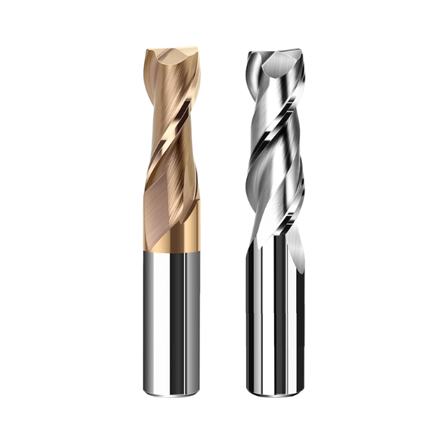
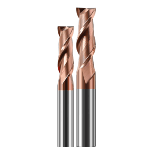
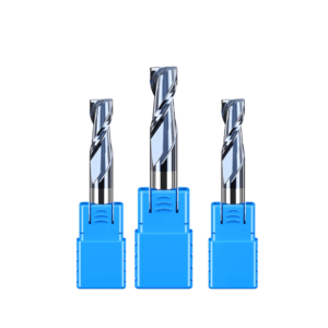
Compared to multi-flute tools, 2 flute end mills for plastic offer larger chip evacuation space and lower cutting resistance, making them better suited for plastics and soft materials. However, proper matching of tool structure, cutting parameters, and machining strategy is critical. Excessive spindle speed, insufficient feed rate, or improper cutting depth can turn a 2-flute tool from an effective cutter into a source of frictional heat, increasing the risk of plastic melting.
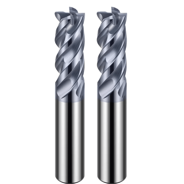
Many machinists select 2 flute roughing end mills during roughing stages to maximize material removal, but if the serrated structure, helix angle, or edge sharpness is not suited for the plastic material, it can cause rapid local temperature rise, incomplete chip breakage, and visible melting on the workpiece surface. These problems usually result from the combined effects of tool design, parameter settings, and machining strategy.
Avoiding plastic melting requires systematic optimization of tool geometry, cutting parameters, chip evacuation methods, and material characteristics. Experienced companies often collaborate with customized carbide end mill suppliers to produce two-flute tools optimized for specific plastic materials and cutting conditions, ensuring stable cutting and controlled temperature rise.
Analysis of Common Melting Problems in Plastic Processing with 2 Flute End Mills
Even high-performance 2 flute end mills can cause surface melting, streaking, or localized sticking during plastic processing. These issues usually stem from heat buildup, poor chip evacuation, and mismatched tool geometry. During high-speed or deep groove cutting, inadequate heat dissipation can lead to localized softening, negatively affecting surface finish and dimensional accuracy.
Analyzing these issues helps understand how to optimize cutting parameters, improve chip removal, and select the right tool geometry to prevent plastic melting and ensure consistent machining results.
Heat Accumulation is the Core Cause of Plastic Melting
Plastics have low thermal conductivity, and prolonged cutting creates high-temperature zones at the tool-workpiece interface. Even with shallow cuts, excessive spindle speed or slow feed can rapidly generate heat, causing the material to soften before cutting. Heat concentration can also lead to chip adhesion on the tool, increasing load and reducing cutting efficiency.
Controlling heat involves adjusting spindle speed, feed rate, and cutting depth. Intermittent cutting or optimizing the tool’s chip flute design can also reduce heat accumulation in the cutting zone.
The Impact of Poor Chip Evacuation
If chips are not removed efficiently, they may be crushed repeatedly, generating frictional heat that worsens plastic melting. Even though 2 flute end mills provide large chip evacuation space, chip buildup can occur during deep groove or continuous cutting. Retained chips can damage surfaces, increase tool wear, and cause sticking or burring.
Effective strategies include using compressed air for chip removal, choosing proper helix angles and flute lengths, and separating roughing from finishing operations to ensure timely chip evacuation.
Frictional Heat from Mismatched Tool Geometry
Edge sharpness, rake angle, and relief angle determine cutting resistance and frictional heat. Unsuitable geometry can generate excessive localized heat, even with smooth chip evacuation. Dull edges, improper helix angles, or mismatched tool diameter and cutting depth increase friction, causing the plastic to soften or melt.
Optimizing edge sharpness, helix angle, and tool overhang length for the specific plastic material can reduce frictional heat. Collaborating with carbide end mill suppliers allows production of two-flute tools optimized for plastic processing, improving surface quality and machining stability.
Choosing the Right 2 Flute End Mill for Plastic
Tool selection directly affects cutting efficiency, surface finish, and machining stability. 2 flute end mills are widely used for plastics like acrylic, ABS, and POM due to smooth chip evacuation and low cutting resistance. Proper selection reduces the risk of plastic melting, extends tool life, and minimizes rework.
Consider material properties, cutting depth, spindle speed, workpiece structure, and tool geometry. In high-speed or continuous cutting, chip evacuation and edge sharpness are critical. For specific applications, customized carbide end mills from suppliers can optimize results for high precision and efficiency.
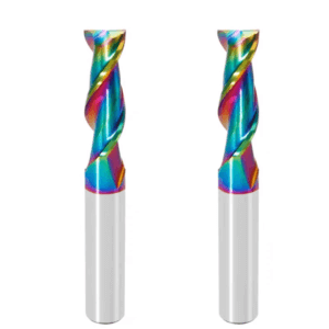
Advantages of 2 Flute Design for Chip Evacuation
Two-flute tools provide larger chip evacuation space than multi-flute tools, allowing chips to leave the cutting zone quickly and reducing friction heat caused by chip accumulation. This is especially important for deep grooves, blind holes, or long workpieces.
Smooth chip evacuation reduces local heat, prevents surface scratching, and avoids tool sticking caused by recirculated chips. Selecting proper flute length and helix angle further optimizes chip flow, maintaining controllable temperature and stable machining.
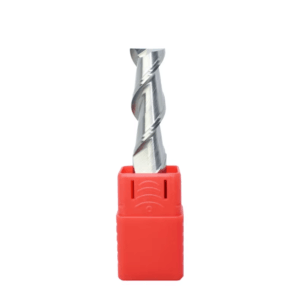
Cutting Edge Sharpness to Prevent Material Softening
Sharp edges lower cutting resistance, ensuring material is cut rather than rubbed, reducing the risk of softening or melting. Dull or worn edges increase friction heat, causing melting or surface scratches.
Edge sharpness should match feed rate and spindle speed. Using two flute end mills optimized for plastics—or customized carbide tools from a supplier—helps control localized heat while maintaining cutting efficiency.
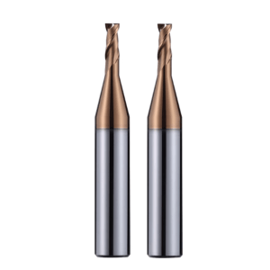
Matching Tool Diameter and Cutting Depth
Mismatched tool diameter and cutting depth often cause tool vibration and localized heating. A small diameter for a deep cut increases uneven stress and friction heat, while a large diameter for a shallow cut may reduce cutting efficiency.
Matching tool diameter, cutting depth, step-over, and cutting method ensures stable temperature, smooth chip evacuation, and reduced melting risk. For complex parts or special plastics, customized two-flute carbide tools precisely control tool-workpiece contact while maintaining efficiency and surface quality.
Cutting Parameter Mistakes: Main Cause of Plastic Melting
Proper cutting parameter settings are crucial for maintaining machining quality and preventing plastic melting. Even with sharp, two-flute tools that allow smooth chip evacuation, mismatched spindle speed, feed rate, or cutting depth can lead to excessive localized heat, causing the plastic in the cutting zone to soften or melt. Machining efficiency and surface quality depend on both the tool and the cutting conditions. Optimizing parameters, controlling heat buildup, and ensuring proper chip flow are essential to prevent melting.
During deep groove, long workpiece, or continuous cutting operations, improper parameters increase tool load and chip retention, leading to material stringing, sticking, or melting. Adjusting parameters according to material properties and tool geometry keeps localized heat under control while maintaining cutting efficiency.
Localized Heat from Excessive Spindle Speed
Excessive spindle speed increases friction frequency between the tool and workpiece, causing rapid localized heat buildup. This is especially critical when machining hard plastics such as acrylic or engineering plastics. At high speeds, chips cannot evacuate in time, leading to melting or material stringing.
Controlling spindle speed, along with proper feed rate and cutting depth, reduces friction heat, ensures smooth chip removal, and minimizes material softening. Intermittent cutting can also be used to manage localized temperature in high-efficiency operations.
Slow Feed Rate Causes Friction-Dominated Cutting
A slow feed rate keeps the tool in contact too long, turning cutting into friction. Chips may stick to the tool, forming molten material buildup, affecting surface finish and dimensional accuracy.
Increasing feed rate allows the tool to cut more material per revolution, reducing friction time and heat accumulation. Feed should be optimized with spindle speed, tool geometry, and material hardness to avoid tool overload or plastic melting.
Cutting Depth and Stepover Affect Heat Concentration
Excessive depth or insufficient stepover increases cutting resistance and concentrates heat in the cutting zone, causing softening or melting. Long tool overhangs exacerbate this effect during deep groove or contour milling.
Matching tool diameter, cutting depth, and chip load per tooth balances cutting forces and heat distribution, ensuring smooth chip evacuation and reducing the risk of melting. For complex plastics or workpieces, optimized two-flute carbide tools can better control temperature and surface quality while maintaining efficiency.
Correct Use of 2 Flute Roughing End Mills in Plastic Rough Machining
Rough machining removes most material and prepares the part for finishing. Even with two-flute roughing tools, improper cutting parameters or tool geometry can cause localized melting, sticking, or surface streaking. Optimizing tool geometry, cutting strategy, and multi-stage machining effectively controls heat while maintaining efficiency and surface quality.
Using a 2-flute roughing end mill requires matching serrated edge design, cutting speed, feed rate, and depth to avoid heat concentration. Roughing should be separated from finishing tools, focusing on material removal, while finishing ensures surface quality and dimensional accuracy, preventing plastic melting.
Serrated Edges Reduce Heat in Rough Machining
Serrated edges divide material into segments, reducing tool load and cutting resistance, minimizing heat buildup. For deep grooves or large-area plastic parts, serrated edges maintain chip breakage, preventing backflow and frictional heating.
Optimizing serration spacing, number of teeth, and helix angle improves chip flow. Combined with appropriate speed and feed, tool temperature during roughing remains controlled, providing stable finishing conditions.
Avoid Using Metal Machining Parameters Directly
Applying metal machining feed rates or cutting depths to plastics increases cutting resistance and local heat. Plastics’ low thermal conductivity causes rapid heat accumulation, leading to softening, melting, or sticking.
Adjust cutting depth, stepover, and feed based on tool geometry and material properties. Intermittent cutting and compressed air for chip removal further reduce heat accumulation.
Importance of Separating Roughing and Finishing 2 Flute End Mills
Separating tools defines machining stages: roughing focuses on rapid material removal and heat control, finishing on surface quality and dimensional accuracy. This reduces tool wear, localized heating, and melting.
Combining 2 flute roughing and finishing tools, possibly through collaboration with a carbide end mill supplier, improves efficiency, surface consistency, and workpiece quality.
The Impact of Machine Tools and Machining Methods on Plastic Melting
The stability of plastic machining is influenced not only by cutting tools and parameter settings, but also by machine rigidity, machining methods, and toolpath planning. These factors directly affect heat control and the likelihood of material melting. Even when using sharp two-flute tools with good chip evacuation capability, insufficient machine rigidity, improper machining strategies, or poorly planned toolpaths can still cause localized overheating, increased vibration, and surface melting.
By properly matching machine performance with machining methods and cutting strategies, vibration can be minimized, chip flow can be improved, and localized heat buildup can be effectively controlled. This becomes especially critical in deep groove machining, continuous contour milling, or complex part geometries, where cutting stability and surface quality are highly sensitive to machine and process conditions.
Tool Vibration and Heat Buildup Caused by Insufficient Spindle Rigidity
Insufficient spindle rigidity leads to micro-vibrations during cutting, resulting in uneven contact between the tool and the workpiece. This uneven engagement concentrates cutting forces in localized areas, causing rapid heat buildup. Vibration not only increases cutting resistance but also disrupts chip formation, leading to chip congestion and localized plastic melting.
These effects are more pronounced during deep groove machining or when processing long workpieces. Selecting a machine with adequate rigidity, minimizing tool overhang, and controlling cutting depth can significantly reduce vibration-related heat accumulation while improving dimensional accuracy and surface finish.
Temperature Differences Between Full-Slot Machining and Side Milling
During full-slot machining, the cutting edge is fully engaged with the material, greatly increasing cutting resistance and frictional heat. This often results in excessive localized temperatures that can cause plastic softening or melting. In contrast, side milling engages only part of the cutting edge, allowing cutting forces and heat to be distributed more evenly, which helps reduce localized temperature rise.
For plastic machining, the machining method should be selected based on part geometry and material removal requirements. Controlling tool engagement, along with appropriate feed rates and cutting depths, helps manage heat distribution and improves surface quality.
The Role of Toolpath Planning in Chip Evacuation and Cooling
Toolpath planning has a direct impact on chip flow and heat accumulation. Poorly designed toolpaths can cause repeated cutting in the same area, leading to chip buildup and concentrated heat, which accelerates melting. Proper toolpath design distributes cutting loads evenly and ensures timely chip evacuation, reducing localized heat buildup.
In complex contour machining or large-area plastic parts, optimizing cutting direction, entry and exit strategies, and layered cutting approaches improves chip evacuation efficiency and reduces frictional heat. These measures help minimize melting, stringing, and tool sticking while improving surface consistency.
Cooling and Chip Evacuation Strategies in 2 Flute End Mill Plastic Machining
Even when using two-flute tools with good chip evacuation performance, plastic melting and material stringing can still occur if heat in the cutting zone is not properly managed. Effective cooling and chip evacuation strategies help control localized temperature rise, improve cutting conditions, and ensure machining stability and surface quality. Methods such as compressed air assistance, controlled use of cutting fluids, and optimized chip evacuation paths significantly reduce frictional heat at the tool–workpiece interface.
In high-speed or deep groove machining, heat accumulates rapidly, and trapped chips can easily cause secondary melting. Combining appropriate cooling methods with effective chip evacuation is essential for maintaining consistent surface quality and minimizing thermal damage.
Practical Benefits of Compressed Air in Plastic Machining
Compressed air effectively removes chips from the cutting zone while carrying away some of the generated heat. This prevents chips from repeatedly rubbing against the tool and workpiece surface, which would otherwise increase frictional heat. For heat-sensitive plastics such as acrylic, ABS, and POM, compressed air significantly reduces material stringing, melting, and tool adhesion.
In deep grooves or continuous contour milling, properly adjusting air pressure and direction ensures timely chip removal, reduces localized heat buildup, maintains sharp cutting action, and improves machining efficiency and surface finish.
When Traditional Cutting Fluids Are Not Recommended
While cutting fluids are commonly used in metal machining, their application in plastic machining requires caution. Liquid coolants can cause certain plastics to absorb moisture and swell, leading to surface discoloration or increased chip adhesion. In some cases, excessive coolant flow can actually obstruct chip evacuation and contribute to localized heat buildup.
For plastic machining, cooling methods should be selected based on material properties and tool geometry. Compressed air or controlled micro-spray cooling is often more effective than high-volume liquid coolant.
Importance of Timely Chip Removal to Prevent Secondary Melting
Chip accumulation in the cutting zone increases frictional heat and can lead to secondary melting of plastic materials. Timely chip removal reduces localized temperature rise and prevents chips from being repeatedly pressed against the workpiece surface, which can cause stringing and adhesion.
Effective chip evacuation is achieved through a combination of optimized tool geometry, proper toolpath planning, and suitable cooling methods. Selecting appropriate helix angles and cutting edge lengths, combined with compressed air assistance, allows chips to exit the cutting zone smoothly. This is especially critical in deep grooves, blind holes, and complex contours.
Preventing Plastic Melting Through Customized 2 Flute End Mills Design
Tool design plays a decisive role in heat distribution, chip evacuation efficiency, and surface quality during plastic machining. Even experienced machinists often find it difficult to eliminate melting, stringing, and chip adhesion using standard tools alone. Customized tools allow cutting edges, rake angles, and helix angles to be optimized for specific plastic materials, resulting in a more stable cutting process and more uniform heat distribution.
In high-speed cutting, deep grooves, or complex contours, customized tools can be precisely engineered to match cutting loads and material characteristics. This maximizes chip evacuation efficiency, improves cutting performance, and supports consistent surface quality and dimensional accuracy.
Optimized Cutting Edge and Rake Angle for Plastic Materials
Cutting edge sharpness and rake angle directly influence cutting resistance and heat generation. Optimized cutting edges for heat-sensitive plastics reduce friction, lower localized heat buildup, and prevent chip adhesion and material melting.
Proper rake angle design improves cutting force direction, smooths cutting action, and reduces uneven tool loading and vibration. This results in better surface finish, improved dimensional control, and increased stability in deep groove or continuous contour machining.
How Customized Helix Angles Improve Heat Distribution
The helix angle significantly affects chip flow and heat distribution. A customized helix angle allows chips to evacuate smoothly along the flute, reducing heat concentration in the cutting zone and lowering the risk of surface melting.
In high-feed or large-area machining, optimized helix angles also help distribute cutting forces more evenly, reduce vibration, and improve surface consistency. Working closely with a end mill supplier makes it possible to select the most effective helix angle for specific materials and machining conditions.
Advantages of Working with a Customized Carbide End Mill Supplier
Partnering with a professional end mill supplier enables the customization of 2 flute carbide end mills based on material type, machining method, and accuracy requirements. Experienced suppliers provide expertise in tool geometry optimization, carbide selection, and coating options, helping to reduce melting, tool adhesion, and surface defects.
Customized tools offer stable performance in both roughing and finishing operations, improve chip evacuation and heat control, extend tool life, and enhance machining efficiency. For complex parts or high-precision applications, collaborating with a specialized supplier is an effective way to ensure consistent quality and reduce rework.
Checklist for Preventing Plastic Melting During Machining
In plastic machining, excessive cutting heat and poor chip evacuation are the primary causes of melting, stringing, and tool adhesion. Even when using two-flute end mills with sharp cutting edges and good chip evacuation performance, defects can still occur without systematic process control. Establishing a structured machining checklist helps maintain consistent cutting conditions throughout pre-machining, machining, and post-machining stages, ensuring surface quality, dimensional accuracy, and process stability while extending tool life.
By implementing phased inspections—such as tool condition verification, parameter validation, real-time machining observation, and post-machining surface evaluation—potential issues can be identified and corrected early. This approach effectively reduces rework and material waste caused by plastic melting, especially in deep grooves, complex contours, or high-speed machining applications.
Tool and Parameter Verification Before Machining
Before machining begins, confirm that the tool geometry, cutting edge sharpness, and flute length are appropriate for the required cutting depth. Ensure that tool overhang is minimized to reduce vibration and localized heat concentration. At the same time, verify that spindle speed, feed rate, and cutting depth are properly matched to the plastic material and machining objectives.
Additionally, confirm that the tool is securely clamped, chip evacuation paths are unobstructed, and auxiliary cooling methods—such as compressed air—are available if required. A thorough pre-machining check significantly reduces the risk of plastic melting and tool adhesion during startup and provides stable conditions for subsequent operations.
Abnormal Conditions to Monitor During Machining
During machining, closely observe chip formation, tool vibration, and the condition of the workpiece surface. Long, stringy chips or chips adhering to the cutting edge often indicate insufficient feed rate or poor chip evacuation. Tool vibration or abnormal noise may signal excessive cutting load or machine rigidity issues, both of which contribute to localized heat buildup. Visible melting, stringing, or discoloration on the workpiece surface indicates that cutting parameters require immediate adjustment.
By monitoring these conditions in real time, corrective actions—such as increasing feed rate, reducing spindle speed, adjusting cutting depth, or improving chip evacuation—can be implemented promptly to control heat generation and prevent surface defects.
Evaluating Thermal Damage After Machining
After machining, inspect the workpiece surface for signs of thermal damage, including melted edges, burr formation, tool material adhesion, or localized deformation. This inspection is particularly critical for parts with high-gloss surfaces or tight dimensional tolerances, where minor defects can compromise performance or assembly.
Evaluating chip marks, edge quality, and surface discoloration helps determine whether tool geometry, cutting parameters, and chip evacuation strategies were appropriate. When combined with machining records, these observations provide valuable feedback for optimizing tool selection and process parameters in future production runs, continuously improving machining efficiency and product quality.
Common Issues Encountered When Machining Plastics with 2 Flute End Mills
Different plastic materials have distinct requirements for tool geometry, cutting parameters, and chip evacuation strategies. As discussed throughout this article, even with sharp two-flute end mills and efficient chip evacuation, problems such as edge melting, burrs, tool adhesion, and inconsistent surface finish can still occur if cutting heat, machine rigidity, or process parameters are not properly matched.
Effective plastic machining requires a comprehensive approach that integrates tool selection, parameter optimization, cooling and chip evacuation methods, and appropriate roughing and finishing strategies based on material characteristics. Systematically summarizing machining experience across different plastics enables machinists to quickly identify potential issues, apply corrective measures, reduce tool wear and rework, and improve overall machining consistency.
Common Melting and Tool Adhesion Issues in Acrylic Machining
Acrylic is highly sensitive to heat and is prone to melting or adhering to the cutting tool when local temperatures rise rapidly. Common defects include melted edges, burr formation, and fine surface scratches, particularly in high-gloss applications. These issues are typically caused by excessive spindle speed, insufficient feed rate, overly aggressive cutting depth, or inadequate chip evacuation.
Using a two-flute end mill designed for smooth chip evacuation, maintaining extremely sharp cutting edges with appropriate rake angles, optimizing cutting parameters, and employing compressed air for chip removal can significantly reduce edge melting and tool adhesion. These measures greatly improve surface finish and dimensional accuracy in acrylic machining.
Temperature Control Considerations for ABS and POM Machining
ABS and POM offer higher toughness and better heat resistance than acrylic, but excessive heat buildup during high-speed machining or deep groove cutting can still cause surface discoloration, micro-melting, or material stringing. Effective heat control strategies include reducing cutting depth, optimizing stepover, balancing spindle speed and feed rate, and ensuring continuous chip evacuation.
During roughing operations, using an optimized two-flute roughing end mill can help reduce cutting heat and tool load. In finishing operations, maintaining sharp cutting edges and selecting an appropriate helix angle are essential for achieving stable cutting conditions and high-quality surface finishes.
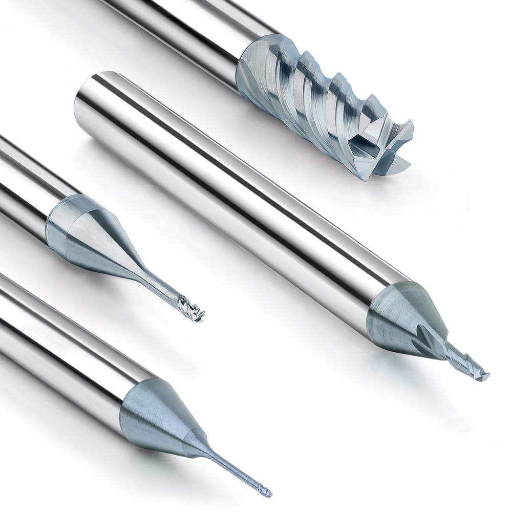
Tool Geometry Requirements for Different Plastic Materials
Different plastics place varying demands on tool geometry and chip evacuation capability. Heat-sensitive materials such as acrylic require extremely sharp cutting edges and unrestricted chip flow, while tougher plastics like ABS and POM demand greater tool stability and controlled cutting resistance. Mismatches in tool diameter, helix angle, or cutting edge geometry can easily result in localized frictional heating, melting, or tool sticking.
By working with a professional supplier to customize carbide two-flute end mills—optimizing cutting edges, rake angles, and helix angles for specific materials—machinists can achieve better heat control, more efficient chip evacuation, longer tool life, and consistent surface quality across a wide range of plastic machining applications.