In our long-term experience providing tooling solutions to European and American machining clients, we frequently encounter the same problems: burrs, chip buildup, or uneven surface roughness during aluminum machining. This happens even when using tools marketed as suitable for aluminum and often fails to meet batch processing requirements. We’ve found that the issue is rarely about a single tool. Instead, it arises from the entire process, from selecting the right aluminum end mill to fine-tuning machining parameters.
In practice, we often observe this scenario: clients use ordinary tools for large-allowance cutting, resulting in excessive cutting load and shortened tool life. Meanwhile, in the finishing stage, the end mill bits aluminum used may lack the proper helix angle or optimized cutting edges for aluminum. As a result, surface quality tolerances are not consistently met. Using an aluminum roughing end mill for staged material removal, combined with cutting parameters verified on-site, typically reduces chipped blades and chip buildup.
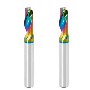
Additionally, our collaboration with multiple carbide end mill for aluminum manufacturers has highlighted an important pattern: even small differences in tool material or coating treatment directly impact cutting stability and tool lifespan. This is especially critical in mass production lines in Europe and the U.S. Only by appropriately matching tool geometry, number of flutes, helix angle, and machining conditions for specific aluminum alloys, such as 6061 and 7075, can we ensure parts achieve the required surface finish while maintaining efficiency.
Therefore, when machining aluminum, selecting an end mill that truly fits the specific conditions—while avoiding rework and tool waste—remains a recurring topic in our on-site discussions with clients. Have you encountered similar challenges?
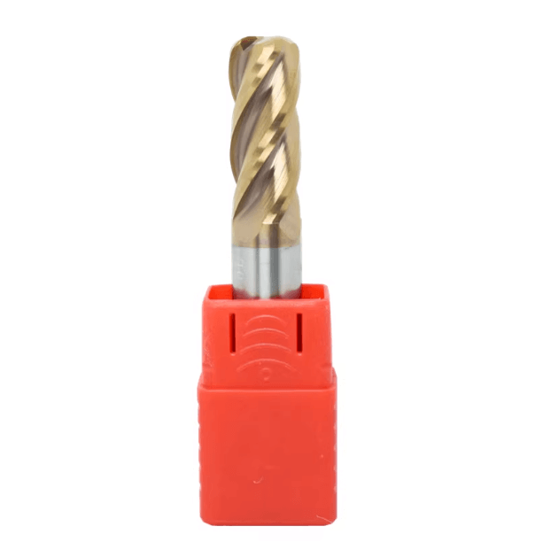
Selecting the Right End Mill Based on Aluminum Type
When machining different aluminum parts, the first consideration is the material’s hardness and cutting behavior. Soft aluminum, like the 1050 or 1100 series, requires lower cutting forces but tends to stick to the tool. Hard aluminum, such as 7075 or 6082, generates higher cutting resistance and accelerates tool wear. If the tool geometry or number of flutes is inappropriate, the tip can chip or vibrate easily. On-site, we first assess aluminum hardness, then consider machining allowance and part geometry to determine the optimal tool choice. This approach reduces tool changes and machining instability.
We have also found that machining environment impacts tool performance. High-speed spindles paired with dry or minimal-liquid cutting exacerbate chip buildup in soft aluminum. Hard aluminum under high-feed, high-speed conditions often shows reduced tool life. Therefore, we take groove depth, helix angle, and coating into account when selecting an aluminum end mill. This ensures both efficiency and consistent surface finish in batch production.
The Impact of Machining Differences Between Soft and Hard Aluminum
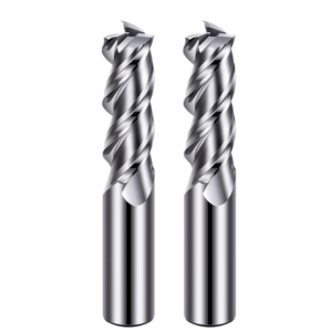
Soft and hard aluminum place very different demands on cutting tools. In soft aluminum, a 2 flute aluminum end mill is prone to built-up edge if chip evacuation is inadequate. We typically select high-helix or polished groove tools to improve chip removal. Feed rates are adjusted to prevent material from fusing at the cutting edge.
Hard aluminum requires a different approach. In 7075 alloy, ordinary aluminum tools often fail quickly due to insufficient tip wear resistance. Through repeated field testing, we prefer carbide end mills from high-wear-resistant aluminum manufacturers. A 3- to 4-flute structure with a medium helix angle provides more stable tool life and surface quality during high-speed, large-allowance cutting.
Practical Tool Case Sharing for 7075, 6061, and 5052 Aluminum
We frequently work with 7075, 6061, and 5052 aluminum alloys. For 7075, its high strength demands robust tools. Using a high-wear-resistant aluminum roughing end mill for staged roughing reduces chipping risk. During finishing, polished groove end mill bits aluminum ensures smooth surfaces while minimizing vibration and burrs.
6061 and 5052 are easier to machine. 6061 requires good chip removal and anti-sticking performance; 5052 is soft, and we often use a 2-flute high-helix aluminum end mill for thin-walled or slender parts. These cases demonstrate that tool selection must match aluminum type, machining allowance, part geometry, and machine performance. Without this alignment, even high-quality tools may not provide stable results.
Selecting Number of Cutting Edges and Helix Angle Based on Aluminum Hardness
Through years of solving aluminum machining challenges, we have developed a practical rule: harder aluminum requires more cutting edges while maintaining a medium helix angle (35°–45°) to balance cutting forces and chip removal. For 7075, we use a 4-flute aluminum end mill with medium helix for stability and extended tool life. Softer aluminum often uses a 2-flute high-helix end mill to accelerate chip removal and prevent sticking.
We also make localized adjustments based on part thickness and groove depth. Deep grooves or long cavities may require a slightly reduced helix angle to prevent vibration. Thin-walled parts benefit from high-helix polished groove tools to reduce cutting force concentration and burr formation. This experience allows us to optimize tool life, machining stability, and surface quality for different aluminum hardness levels.
End Mill Matching Strategy for Roughing and Finishing
In our machining projects, large-allowance cutting and finishing often require a combination of tools. Even high-end individual tools cannot always guarantee machining efficiency and part quality. We have observed that using finishing tools directly for roughing causes rapid tool wear and significant vibrations, especially on large aluminum sections. Conversely, using only roughing tools for finishing fails to meet surface roughness requirements, and burrs are easily generated. After multiple on-site verifications with customers, we typically pair aluminum roughing end mills with high-polish groove end mills for aluminum to achieve a balanced process.
We also adjust the matching based on part geometry and machine tool performance. For deep cavities or long grooves, the roughing tool’s cutting edge length and helix angle must balance chip removal and cutting force distribution. The finishing tool, in contrast, focuses on surface quality and vibration control. This layered approach reduces tool change frequency, ensures machining efficiency, and minimizes batch rework caused by tool mismatches.
Experience Summary of Aluminum Roughing End Mill in Large-Margin Cutting
When mass-producing aluminum alloy parts for European and American customers, we found that large-margin cutting is prone to tool chipping and machine vibration. To address this, we prefer specialized aluminum roughing end mills with slightly rounded tips and deeper flutes. These features help evacuate chips quickly and reduce cutting force concentration during heavy material removal.
In field tests, we compared tools with different flute counts and helix angles. Three- to four-flute tools perform more stably in hard aluminum, while two-flute tools offer higher efficiency in soft aluminum. We also fine-tune feed rate and depth of cut on-site. For thick 7075 aluminum parts, we typically set depth of cut at 20%–25% of tool diameter per pass and maintain feed rate near our empirical maximum. This ensures the tool does not overheat or vibrate while achieving a balance between tool life and stability.
Measured Parameters of Finishing End Mill in Thin-Wall Part Machining
Finishing thin-walled parts is often one of the most challenging issues for customers. In multiple field tests, we observed that thin-walled aluminum is prone to deformation or vibration due to uneven cutting forces, while ordinary roughing tools are insufficient for achieving required surface quality. Therefore, we use a finishing end mill with moderate cutting edge length and a moderately higher helix angle, combined with polished grooves or low-viscosity coatings.
In terms of parameters, we reduce feed per tooth and depth of cut while maintaining high spindle speed. This ensures smooth, vibration-free cutting. Parts achieve the required surface roughness with minimal burrs or deformation. These methods have been validated in mass production by multiple customers, though adjustments remain necessary depending on aluminum type and wall thickness.
How to Achieve High-Efficiency One-Shot Machining with End Mill Bits Aluminum
At our European and American customer sites, clients often aim to complete machining with the fewest tools possible. From practical tests, we found that a single tool rarely achieves both high roughing efficiency and finishing quality. We therefore use a layered approach with end mills and aluminum bits. Typically, we start with an aluminum roughing end mill to remove bulk material quickly, then switch to a high-gloss finishing tool for thin-walled or detailed areas.
We also optimize locally based on part characteristics. For complex geometries or deep cavities, a shorter finishing tool reduces vibration risk. For open, large flat surfaces, a standard-length, highly polished fluting tool improves feed efficiency. This combination allows most machining operations to be completed in a single clamping, maintaining efficiency while controlling tool and material wear.
Practical Experience in Tool Geometry and Chip Evacuation Design
Tool geometry and chip evacuation directly affect machining stability and surface quality. We often encounter vibration, burrs, or uneven surfaces caused by end mills not optimized for aluminum. Fine-tuning helix angle, number of flutes, and groove shape significantly improves stability, particularly in deep cavities or large allowances, while extending tool life.
Machine rigidity also plays a critical role. The same aluminum end mill may vibrate on low-rigidity machines if the helix angle or cutting edge length is too high. On high-rigidity machines, the same tool can achieve high-efficiency machining. We therefore select tool geometry based on machine and part structure, rather than relying solely on tool specifications.
The Influence of Helix Angle, Number of Cutting Edges, and Groove Type Selection on Cutting Stability
Helix angle is a key factor in cutting stability. For soft aluminum, we use high helix angles to improve chip removal and reduce sticking. For hard aluminum or thick parts, we prefer a medium helix angle to balance cutting forces and reduce tool tip wear. Flute count matters too: two-flute tools work well for thin-walled soft aluminum, while three- to four-flute tools are necessary for large hard aluminum sections.
Groove shape is also critical. Deep grooves enhance chip removal, but excessive depth reduces rigidity and increases vibration risk. Shallow grooves improve rigidity but may limit chip removal, causing buildup. Through repeated testing, we balance helix angle, flute count, and groove depth for optimal performance on specific aluminum alloys and part geometries.
Our Groove Shape Optimization for Aluminum End Mills in Long Grooving and Deep Hole Machining
In long groove and deep-hole machining, groove shape directly affects chip evacuation and cutting stability. Customers often face tool clogging or vibration, causing surface defects. We select aluminum end mills optimized for deep grooves, polished grooves, or spiral chip removal. Cutting edge length is adjusted to part length to maintain smooth chip removal.
Further adjustments are based on spindle power and fixture rigidity. For some deep-hole aluminum parts, long-bladed cutters may provide good chip removal but insufficient rigidity can cause vibration. In such cases, we reduce helix angle or shorten the effective cutting edge while fine-tuning feed and depth of cut. This approach minimizes tool wear and rework for complex parts.
Micro-Vibration, Chip Accumulation, and Solutions
Micro-vibration and chip accumulation are common in aluminum machining. Thin-walled or deep-groove parts frequently experience minor vibrations, leading to burrs or uneven surfaces, even with commonly used end mill bits aluminum. To address this, we first adjust tool geometry: helix angle, flute count, and groove shape.
On-site, we fine-tune feed per tooth, depth of cut, spindle speed, and apply slight liquid cooling. These engineer-level adjustments often outperform relying solely on tool specifications, providing results aligned with actual production needs.
End Mill Material and Coating Selection
In our long-term experience providing aluminum machining solutions to European and American clients, tool material and coating are critical factors affecting machining stability and tool life. We frequently encounter situations where ordinary carbide tools used for high-speed aluminum cutting wear rapidly or aluminum adheres to the cutting edges, causing uneven surface finish. Adjusting cutting parameters alone often cannot fully solve these issues, which makes selecting the appropriate carbide end mill and coating type essential.
We have also observed significant differences in how materials and coatings perform under various machining conditions. In soft aluminum batch production, tools with highly polished grooves and low-friction coatings reduce chip buildup and sticking. In contrast, machining hard aluminum or large-allowance parts benefits from solid carbide tools with higher wear resistance and lighter coatings. We make comprehensive judgments based on part material, cutting conditions, and machine tool rigidity rather than relying solely on tool specifications.
Recommended Carbide End Mill Models and Lifespan Performance in Practice
In our daily projects, we have tested carbide end mills from multiple manufacturers, evaluating wear resistance and lifespan using on-site production data. For example, during high-speed cutting of 7075 aluminum, some carbide tools performed consistently for over five hours, while ordinary tools lasted only 1–2 hours before chipping or accumulating aluminum on the tip. Based on these tests, we select models that balance lifespan and stability according to part size, cutting allowance, and machine rigidity.
We also found that cutting edge shape and helix angle significantly influence performance. High-helix tools reduce vibration in thin-walled hard aluminum parts but may wear faster under prolonged large-allowance cuts. Medium-helix tools offer more stable performance for large parts. Our selection is guided by field experience rather than solely by tool manuals.
The Actual Impact of Coatings on Aluminum Adhesion and Surface Quality
In practice, coatings directly affect aluminum machining. For soft aluminum, uncoated end mill bits aluminum often cause rapid chip accumulation and poor surface finish. Using ZrN or DLC-coated tools improves chip evacuation and anti-adhesion, leading to smoother surfaces and a 30%–50% increase in tool life.
However, coatings are not a universal solution. Hard aluminum machined at high speed with large allowances can suffer from excessive cutting resistance if coatings are too hard or thick, causing tip chipping. We select tools with moderate coating hardness and thickness, combined with appropriate helix angle and flute count, to balance anti-adhesion and cutting stability effectively.
First-Hand Comparison of End Mill Bits Aluminum Materials from Different Suppliers
In long-term collaborations, we frequently compare end mill bits aluminum from multiple suppliers, assessing carbide density, uniformity, and cutting edge sharpness on-site. Even with identical specifications, supplier differences can significantly impact performance. Softer carbide may wear faster on hard aluminum, while high-density tools reduce vibration and maintain smooth surfaces on thin-walled parts.
We also evaluate machining tolerances and polishing processes. Tools with uneven edge polishing or excessively deep grooves tend to accumulate chips in soft aluminum, causing burrs. Through these comparisons, we select suitable tool combinations efficiently, improving machining stability, batch consistency, and reducing tool change frequency.
Cutting Parameter Optimization and Practical Techniques
Tool geometry and material are the foundation, but cutting parameters determine machining efficiency and part quality. Even with a high-quality aluminum end mill, improper spindle speed, feed rate, or depth of cut can cause vibration, burrs, and premature tool wear. We conduct small-batch trial cuts, adjusting parameters based on observed vibration and cutting noise to ensure optimal performance.
Each aluminum alloy has an “acceptable parameter range.” Deviating from this range risks instability. We adjust spindle speed, feed per tooth, and depth of cut based on part thickness, groove depth, allowance size, and the end mill bits aluminum’s flute count and helix angle. This approach maintains high efficiency while minimizing defects and tool waste.
Practical Experience with Spindle Speed, Feed Rate, and Depth of Cut
Aluminum machining is highly sensitive to spindle speed, feed rate, and depth of cut. For thin-walled soft aluminum, we typically use higher spindle speeds, lower feed per tooth, and shallower depths to reduce vibration and burrs while maintaining a smooth surface. For large, hard aluminum, spindle speed is reduced, depth of cut increased, and feed rate adjusted to maintain uniform cutting forces and extend tool life.
We record tool performance on-site to develop reference parameters. Excessive feed per tooth accelerates tip wear; too deep a cut increases vibration and burrs; too slow a spindle reduces chip evacuation. These observations allow us to create parameter tables for quick adjustment in mass production.
Tool Performance Under Dry, Semi-Dry, and Liquid Cooling
Cooling methods dramatically affect tool performance. Thin-walled soft aluminum is prone to sticking in dry cutting, while minimal liquid cooling improves chip removal. Hard, thick aluminum cut at high speeds without cooling sees rapid tip temperature rise and shortened tool life. We choose between dry, semi-dry, and low-volume liquid cooling based on machine and material.
Cooling also impacts surface quality. Appropriate cooling reduces burrs and chatter, while excessive cooling may interfere with chip removal. By combining cooling strategies with aluminum roughing end mills and finishing tools, we make real-time adjustments to ensure stability and extend tool life.
Quick Adjustment for Burrs, Chatter, and Chip Accumulation
Burrs, chatter, and chip buildup are common issues. We first fine-tune feed and depth of cut, observing changes. If necessary, we adjust helix angle or switch to end mill bits aluminum with more suitable cutting edges.
Chip removal and cooling must be coordinated. Chip buildup is mitigated by increasing spindle speed or adding slight coolant; micro-vibration is reduced by lowering feed per tooth or shortening cutting edge length. These on-site adjustments allow us to quickly resolve problems while building a parameter database for repeatable mass production.
B2B Client Case Sharing
On-site case studies illustrate challenges better than any textbook. Different industries have varying requirements for aluminum machining; each project must be validated based on material, geometry, and production volume. Our experience helps clients overcome vibrating cutters, chip accumulation, and burrs, while building actionable tool selection and cutting parameter knowledge.
Tool and supplier selection cannot be isolated from the machining process. For example, an aluminum roughing end mill works well in automotive large-margin cutting but requires a high-helix finishing tool for thin-walled aerospace parts. Through continuous on-site testing, we built a reference library of tool combinations for different applications, supporting daily B2B customer operations.
European and American Automotive Parts: Aluminum Roughing End Mill Process Improvements
In automotive parts, cutting thick aluminum blocks with large allowances often caused tool tip chipping and chip buildup. On-site, we implemented aluminum roughing end mills with layered cutting and optimized helix angles. This improved cutting force distribution and chip removal, increasing tool life and stability on 7075 and 6061 aluminum.
Tool parameters were fine-tuned for part shape. Long grooves and deep holes required reduced feed and depth to prevent oscillation, while flat or thin areas increased feed for efficiency. These optimizations ensured batch processing was efficient, stable, and consistent in surface quality.
Aerospace Parts: Stability Verification of High-Helix Aluminum End Mills
Aerospace parts often feature hard materials and thin walls, demanding high accuracy. High-helix aluminum end mills improved chip removal and stability. High helix angles reduce oscillation but require precise feed and depth; otherwise, tool tips can wear locally.
We tested different flute counts and coating combinations, ultimately selecting 3–4 flute medium-helix polishing groove tools. This configuration supports thin-walled machining and stable long-batch production, solving oscillation-related rework issues while providing replicable parameters for mass production.
Small OEM Mass Production: Supply Chain Experience of Carbide End Mills
Small OEM clients require stable tool supply with controlled costs. Long-term partnerships with multiple carbide end mill suppliers allow on-site evaluation of material density, cutting edge sharpness, and polishing groove quality. This reduces tool changes and downtime while ensuring stability.
On-site, we optimize machining strategy per tool. Thick aluminum or large-allowance cuts use high-wear carbide; thin-walled or complex parts use polishing groove tools with high-helix finishing tools. This comprehensive tool and supply chain management provides efficient, reliable solutions for small OEMs.