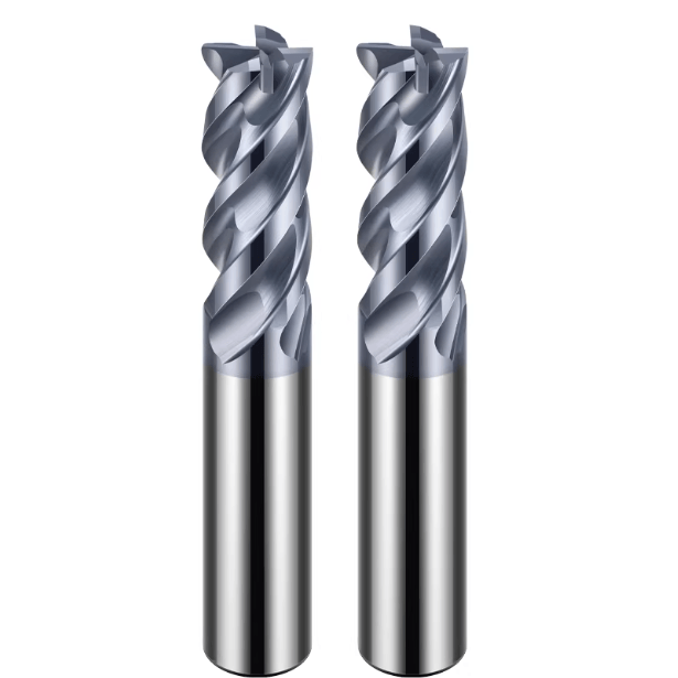
In our long-term experience providing machining solutions to European and American clients, the tolerances of solid carbide end mills are often overlooked, yet they have the most direct impact on machining quality. We have encountered clients who, despite correctly adjusted machine parameters, experienced dimensional deviations and surface scratches in high-precision mold machining. Upon investigation, we often found the cutting tool itself to be the root cause. Whether using high-performance solid carbide end mills or conventional tools, even minute deviations in cutting diameter, cutting length, or the ball nose can be amplified during high-speed cutting or multiple tool changes.
In actual projects, we frequently verify the shank diameter tolerance, cutting edge consistency, and edge grinding quality of solid carbide end mill cutters. This is especially important for small-diameter tools or deep cavity machining, where even slight runout can cause the scrapping of batches. For clients using solid carbide ball nose end mills for 3D surface machining, even tiny errors in the ball nose radius directly affect mold surface finish. Such problems cannot always be corrected with machine tool compensation alone.
As a solid carbide end mill manufacturer, we fully understand the cumulative impact of every step—from raw material selection and grinding processes to coating control—on final tolerances. Before mass production, we conduct on-site testing and verification for each batch of tools. This ensures consistency and reliability during high-speed machining or machining of high-hardness materials. Our practical experience shows that stable tool tolerances are critical for both efficiency and part quality.
In our experience, many competitors overlook the direct impact of tool tolerances. Accumulation of minute deviations is often the root cause of decreased production efficiency and increased rework. Have you ever encountered a situation where a tiny tool error disrupted an entire machining process?

How We Control Critical Tolerances in Solid Carbide End Mills in Actual Production
High-speed spindle machining is almost always the standard in our projects. Any small tool runout can directly affect surface quality and dimensional stability. We have observed European customers using high-performance solid carbide end mills to machine aluminum alloy molds, where tool vibration during high-speed cutting caused cavity dimensional drift. Retrospective inspection revealed an inadequate fit between the tool holder and spindle, along with a tool shank diameter tolerance of ±0.005mm. For deep cavity machining, we target tolerances within ±0.003mm. This minor difference is amplified at high speeds and directly impacts machining stability.
To maintain consistency in mass production, we rigorously test each batch before warehousing, especially the shank diameter and cutting edge diameter. Machine tool compensation alone cannot correct errors caused by tool runout. When customers mass-produce cavities, the tool’s geometric accuracy becomes the most direct guarantee of dimensional stability. This approach reduces rework rates and ensures reliable results during high-speed and deep cavity machining.
Actual Impact of Shank Diameter Tolerance on Runout (±0.003mm vs ±0.005mm)
We clearly observed that small changes in shank diameter tolerance significantly affect tool dynamics. For example, a solid carbide end mill we supplied to a German customer exhibited almost no vibration at 24,000 RPM when the shank tolerance was ±0.003mm, resulting in stable cutting and smooth surfaces. Increasing the tolerance to ±0.005mm caused slight vibration under the same conditions, producing ripples on the machined parts. We recommend tighter tolerances for high-speed or small-diameter tools to minimize dimensional errors caused by runout.
Toolholder fit accuracy is equally critical. Even with well-controlled cutting diameter, improper clamping can amplify vibration. We measure shank diameter and toolholder fit for each batch to minimize runout risk and ensure part consistency on-site.
How Cutting Diameter Tolerance Affects Dimensional Consistency and Batch Stability
In mold cavity batch machining, small differences in cutting diameter can cause dimensional deviations. Especially in deep cavities or high-hardness steel, a 0.01mm deviation can result in the entire batch exceeding tolerance. Our experience shows that cutting diameter stability impacts part consistency more than tool material or coating alone.
We employ full inspection and sampling for mass production. Small batches have almost all diameters measured; large batches use proportional sampling combined with machine tool testing to verify tool stability. This ensures batch consistency and reduces rework caused by diameter drift.
Impact of Cutting Length and Total Length Tolerances on Deep Cavity Machining
Even small errors in cutting length or total length can cause tool interference or collisions, particularly with solid carbide ball nose end mills in multi-axis machining centers. One customer experienced tool breakage and scrap when cutting length exceeded tolerance by 0.1mm, causing fixture collisions.
We conduct full inspections of cutting edge and total length before warehousing and record tool life in our tool management system. For batch or complex parts, we perform additional random sampling and share measurement data with the customer to minimize machining risks.
Concentricity and Runout Control Standards (Measured, Not Theoretical Values)
In high-speed machining, we measured the impact of runout differences of 0.005mm versus 0.01mm. The effect on part quality was greater than theoretical calculations predicted. We supplied high-performance solid carbide end mills to a mold factory; at 0.01mm runout, chipping and tool marks occurred, while 0.005mm runout produced smooth, dimensionally stable surfaces.
Customers sometimes attribute chipping to machine parameters or errors. By measuring tool concentricity, we confirmed that cumulative runout was the main issue. Our practical experience advises peers to prioritize measured runout data when selecting solid carbide end mill cutters, particularly for high-speed or deep cavity machining. This ensures reliable, consistent results.

Special Requirements for Tolerance Control of High Performance Solid Carbide End Mills
High-speed machining and machining of high-hardness materials often place stricter demands on tool geometry accuracy. In our projects, machining steel parts with a hardness of HRC60 or higher using high-performance solid carbide end mills, even minute deviations in the cutting edge can affect cutting force distribution and tool life. Tool material hardness and coating wear resistance alone are not enough to guarantee stability. Strict control of cutting diameter, cutting length, and runout is essential. For customers producing precision cavities in batches, we conduct on-site testing to ensure dynamic balance and dimensional consistency under high-speed cutting.
We frequently encounter situations where the same tool performs differently on different machines. Beyond machine rigidity, the tool’s inherent balance characteristics play a major role. Over years of experience, we developed internal standards, including methods for checking tool concentricity, shank diameter accuracy, and cutting edge consistency. These measures reduce chipping, vibration, and allow predictable machining of complex parts.
High-Speed Machining: Practical Requirements for Dynamic Balancing
When machining aluminum and aerospace parts at rotational speeds above 24,000 RPM, we observed that even a shank diameter deviation within 0.003 mm can cause vibration if the tool is not properly balanced. This vibration directly affects cutting stability and surface finish. We conduct high-speed rotation tests on each cutter before shipment to ensure balance meets client requirements.
We also grade dynamic balance based on material and cutting parameters. In some five-axis high-speed machining scenarios, clients require vibration amplitudes under 0.002 mm. We provide measured data and adjust shank diameter and cutting edge length to minimize dynamic balance errors. High-speed machining is therefore not only a matter of material hardness, but a comprehensive reflection of dynamic stability and tolerance control.
Importance of Cutting Edge Consistency in High-Hardness Material Machining
For steel parts above HRC60 or titanium alloys, minute inconsistencies in cutting edges are amplified by material hardness, causing cutting force fluctuations, abnormal surface texture, or premature tool breakage. In aerospace projects, we resolved uneven cutting issues traced to cutting edge inconsistencies as small as 0.01 mm between batches.
For batch supply of high-performance solid carbide end mills, we perform rigorous cutting edge checks, including tip radius and geometry. For high-hardness material machining, we conduct trial cuts to verify actual performance of each batch, minimizing risks from subtle differences. This practice, developed through years of experience, is the most direct guarantee for challenging machining conditions.
Challenges in Dimensional Control Before and After Coating
During the coating process, even a few micrometers of coating thickness can cumulatively impact tool tolerances. Especially in deep cavity machining, unaccounted coating thickness may result in deviations in cutting diameter or length, increasing cutting forces or causing interference. We encountered customers experiencing minor collisions and surface roughness due to this.
To address this, we perform dimensional compensation before coating, adjusting cutting diameter and length to ensure tolerances remain within specification post-coating. We also re-measure after coating to confirm batch consistency. High-performance tools require integrated consideration of tolerance control, process compensation, and actual machining requirements.

Solid Carbide End Mill Cutter Quality Judgment Standards in Different Application Scenarios
In our machining experience, tool tolerance sensitivity varies greatly depending on material and process. We once supplied solid carbide end mills to European and American clients for both aluminum and steel. Even tools from the same batch showed slight vibration under high-speed aluminum cutting, but remained stable in steel machining. This demonstrates that material properties and cutting conditions directly amplify the impact of tool tolerances on machining quality. Therefore, when judging tool performance, we consider the specific machining scenario, not just manufacturer specifications.
We also observed significant differences in customer expectations across applications. For high-speed aluminum machining, consistent cutting diameter and edge finish are critical. For high-hardness steel, small differences in cutting edge geometry and concentricity have a larger impact on cutting force and stability. In our supply and on-site support, we prioritize inspection standards based on actual machining requirements rather than generic tolerances.
Difference in Tolerance Sensitivity Between Aluminum and Steel Machining
In high-speed aluminum machining, we frequently use high-helix solid carbide end mill cutters for smooth chip removal and surface finish. Even with ±0.003mm tolerances on cutting edge diameter and shank diameter, minute vibrations can create ripples or stepped patterns on the aluminum surface. We encountered aerospace clients whose batch-machined parts required multiple reworks due to vibration-induced surface inhomogeneity. This experience clearly showed that aluminum machining is highly sensitive to dynamic balance and cutting edge consistency.
In contrast, machining steel or high-hardness materials may show less visible vibration, but small differences in the cutting edge and cumulative cutting length errors directly affect cutting forces. This can lead to premature tool breakage or dimensional deviations. We select more stringent cutting edge consistency checks based on material hardness and machining depth, and perform on-site trial cuts to verify tool performance.
Tolerance Control Differences Between Roughing and Finishing End Mills
For roughing operations, slightly larger tolerances are acceptable due to higher cutting forces, faster tool wear, and the goal of removing most of the material allowance. In a batch aluminum profile project, roughing end mills with ±0.005mm diameter deviation met requirements.
During finishing, stricter control of cutting diameter, cutting length, and concentricity is necessary. In complex mold cavity mass production, tolerance control directly impacts part consistency and rework rates. We perform measurements on each batch of high-performance solid carbide end mills and conduct trial cuts to ensure stable performance. This approach reflects years of practical experience.
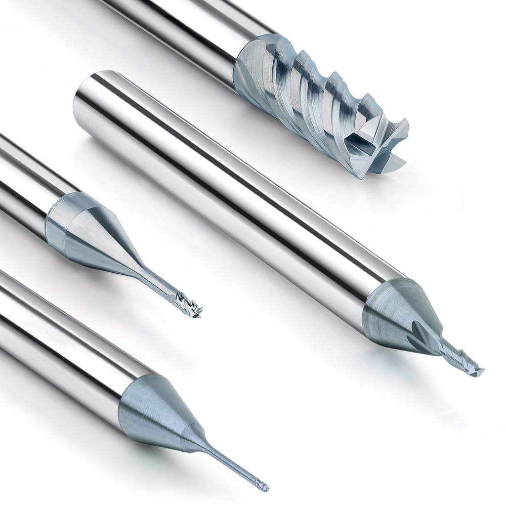
Tolerance Challenges of Small Diameter Cutters (≤3mm)
Machining small-diameter cutters is more challenging than conventional sizes. In our experience, cutters below 3mm are extremely sensitive to shank diameter, cutting length, and cutting edge consistency. One customer faced frequent tool breakage when machining precision molds. Investigation showed that accumulated tool tolerances and high-speed vibration were the main causes.
To reduce breakage, we implement stricter tolerance control and dynamic balancing for small cutters. We also advise adjusting feed rate or depth of cut. This helps minimize breakage while maintaining machining efficiency. Our experience confirms that tolerance requirements for small-diameter tools are far stricter than for standard tools.
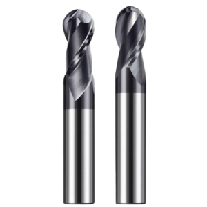
Special Tolerance Control Considerations for Solid Carbide Ball Nose End Mills
Ball end mills require extremely precise control of the radius (R-angle) and ball center. Even minute deviations can create stepped marks or uneven surfaces in mold and complex surface machining. We supplied solid carbide ball nose end mills to a European client, and found step marks in cavity surfaces during batch machining. Measurement confirmed the issue was the ball radius deviation. This highlighted that tolerance control must be maintained from design through manufacturing and delivery.
Machine tools and machining paths amplify any inaccuracy. In five-axis machining, a slight ball center offset can cause path compensation failure, directly affecting surface finish. We combine tool measurement and path testing to predict issues and provide cutting strategy advice to clients.
How Ball End Mill Radius Accuracy Affects Mold Surface Quality
R-radius accuracy directly determines cavity surface smoothness. In one automotive mold project, a 0.01mm radius deviation caused slight step marks at the cavity bottom, requiring additional grinding. The issue was traced to the tool itself, not the machine.
To prevent similar problems, we strictly control cutting edge radius and ball roundness during production. We perform R-angle measurements before shipment and recommend clients conduct small-batch trial cuts on five-axis or high-precision surfaces. This reduces rework or defects due to tool tolerances.
The Impact of Ball Center Position Deviation on 5-Axis Machining
Even a small ball center offset can significantly affect toolpath compensation. In a mold factory project, a 0.02mm ball center deviation amplified path errors, causing overcutting and undercutting. The client initially suspected the machine, but on-site measurements confirmed the tool was the issue.
We measure and record ball center deviation for each batch and provide the data for path verification. This early detection allows fine-tuning of five-axis machining parameters, ensuring part surface consistency. This hands-on experience is more instructive than theoretical calculations, especially in complex curved surfaces and high-precision molds.
Ball End Mill Inspection Methods and Common Misjudgment Issues
Customer measurement methods sometimes misjudge tool accuracy. Some rely solely on CMM to measure ball diameter, ignoring edge roundness and ball center offset. Step marks and path errors can still occur. We have corrected such measurement errors on-site multiple times.
We recommend verifying solid carbide ball nose end mills using factory-measured data, especially for small-radius tools and five-axis high-precision machining. We also provide measurement suggestions, such as edge scanning or ball center checks, to ensure optimal tool performance. These details directly affect surface quality and machining stability.
As a Solid Carbide End Mill Manufacturer, How We Establish Internal Quality Standards
In our long-term experience supplying cutting tools and providing technical support to clients in Europe and America, we’ve found that establishing internal quality standards touches every stage, from raw materials to the final product. For both conventional solid carbide end mill cutters and high-performance tools, early raw material control determines subsequent tolerance stability. Raw material selection, sintering uniformity, and initial rod diameter all directly affect cutting diameter, shank diameter, and cutting length consistency. Without strict internal standards, even refined grinding processes cannot guarantee batch-to-batch performance.
We also observed that the machining environment and equipment stability play a significant role in final tool quality. Years of production experience have shown that batch consistency depends not only on raw materials but also on grinding machine precision, temperature control, and tool fixing methods. We have therefore developed detailed internal process specifications, including grinding sequences, coolant usage, and machine maintenance standards, to ensure every batch of solid carbide end mills meets strict tolerance and cutting performance requirements.
Dimensional Control Logic Starting from Raw Materials (Tungsten Carbide Rods)
We have found that diameter deviation in tungsten carbide rods directly impacts the cutting edge and shank diameter of the finished tool. A customer once reported slight dimensional drift when machining precision molds. Investigation revealed that cumulative deviations in the original rods resulted in a smaller cutting edge. To prevent this, we measure each tungsten carbide rod upon receipt and classify them according to deviation, establishing a stable foundation for subsequent grinding.
We also record batch data for raw materials and compare it with final tool measurements. This traceability system ensures raw material suitability and provides customers with verified tolerance guarantees. This is particularly important when machining high-hardness steel or deep cavities, as even minute deviations can be amplified, directly affecting part dimensional consistency.
The Decisive Role of Grinding Processes in Tolerance Stability
In our experience, different grinding equipment and processes significantly affect batch consistency. For high-performance solid carbide end mills, some batches initially showed uneven cutting diameter and length due to insufficient machine precision. This led to vibration and chipping during high-speed cutting. We realized that grinding is not merely shaping the tool; it is essential for controlling tolerance stability.
We established grinding standards covering tool fixation, grinding sequence, coolant application, and temperature control. Different machines require tailored calibration strategies based on tool diameter, number of cutting edges, and material hardness. These measures maintain consistency in cutting diameter, length, and concentricity, ensuring predictable machining results for high-speed or high-hardness material processing.
Online Inspection and Final Full Inspection Standards
Beyond online inspection during production, we conduct full inspection for each batch. Online inspection rapidly measures shank diameter, cutting edge diameter, and length to identify abnormal batches quickly. Full inspection includes precise measurements of concentricity, cutting edge roundness, and ball end radius, especially for mold-making and five-axis tools.
For example, we established tolerance ranges for European and American clients and adjusted manufacturing based on machine trial cut feedback. This approach ensured batch consistency and provided traceable measurement data. Our experience confirms that relying solely on manufacturer tolerance specifications is insufficient; measured data is the key to guaranteeing high-precision machining performance.
Why Price Differences Between Manufacturers Often Stem from Tolerance Grades
In our supply experience, price differences often reflect variations in tolerance grade and inspection rigor. Lower-priced tools frequently allow larger deviations in shank diameter, cutting edge diameter, and cutting length. High-precision tools ensure consistent tolerances through strict raw material selection, grinding process control, and full inspection.
We explain to customers that higher prices represent a trade-off between cost and precision. In high-speed cutting, high-hardness materials, or deep-cavity mold processing, strict tolerances ensure predictable performance and low rework rates but increase production costs. This understanding allows us to align customer expectations and avoid issues caused by lower-grade tools.
Common Misconceptions We’ve Identified in Supporting Customers in Europe and America
Through years of providing on-site support to clients in Europe and America, we have often observed that customers attribute machining problems solely to tool tolerances while overlooking machine tool factors. In high-speed or complex five-axis machining, insufficient spindle taper, poor clamping accuracy, or inadequate machine bed rigidity can all cause uneven surfaces or part dimensional deviations.
For example, one mold customer using high-performance solid carbide end mills to machine aluminum parts frequently experienced slight vibrations and abnormal surface textures. The customer initially suspected cutting diameter or shank diameter tolerances, but on-site inspection revealed insufficient machine tool clamping accuracy. This confirms that diagnosing machining anomalies requires a comprehensive system-level analysis—from cutting tool and tool holder to the machine tool itself. Tool tolerance specifications alone are insufficient to fully explain machining results. On-site, we typically perform combined measurements of the cutting tool, tool holder, and machine tool, along with trial cuts, to help customers pinpoint the true cause. This approach avoids misjudgments and helps optimize machining processes.
How Customers Often Misattribute Machine Tool Problems to Solid Carbide End Mill Tolerances
Many customers immediately suspect tool tolerances when encountering dimensional deviations or slight surface ripples during high-speed machining or with small-diameter tools. For instance, while machining aerospace aluminum parts, a client experienced continuous cavity deviations and initially assumed a cutting diameter error.
Measurements of the spindle taper and tool holder fit revealed that machine tool clamping deviations were causing slight tool vibrations. We advise customers to first evaluate machine tool factors before considering tool tolerances. This method accurately identifies the source of the problem and avoids unnecessary replacement of high-precision tools. Our experience shows that systematic errors are often easier to overlook than individual tool tolerances.
Systematic Errors Caused by Tool Holder and Tool Tolerance Superposition
In actual machining, tool holder and tool tolerances often combine to create systematic errors. For example, a solid carbide end mill with a ±0.003mm shank diameter tolerance and a tool holder runout of ~0.004mm results in an effective runout of ~0.007mm during high-speed cutting. This is sufficient to impact surface finish and cavity precision.
We recommend that in high-precision applications, customers measure tool holder fit alongside tool tolerances and consider machine rigidity. This allows prediction of systematic errors before batch machining and supports selection of optimal tool and fixture combinations to maximize part quality.
How to Determine Tool Quality Grade Through Simple On-Site Inspections
To help customers quickly assess tool performance, we suggest simple, actionable inspection methods. For solid carbide ball nose end mills or small-diameter end mills, customers can use a micrometer or cutting edge gauge to check consistency of shank diameter, cutting edge diameter, and cutting edge length, comparing results with factory-provided data.
We also guide customers to observe cutting surface and vibration during trial cuts. If abnormal cutting occurs within nominal tolerances, it typically indicates tool holder or machine tool factors rather than tool defects. This quick on-site inspection approach has reduced misjudgments and allowed us to accumulate extensive practical experience supporting clients in Europe and America.

Tolerance Communication Advice from Solid Carbide End Mill Manufacturers to B-End Customers
Through years of on-site technical exchanges with clients in Europe and America, we have found that clear tolerance communication is often more critical than static technical tables. Shank diameter, cutting diameter, cutting edge length, tolerance grade, and cutting edge consistency directly affect machining results. Unclear requirements can lead to blade vibration, chipping, or dimensional drift during mass production.
We recommend prioritizing tolerance discussions during procurement and trial cuts, taking into account machine tool rigidity, fixture fit, and actual material conditions. When purchasing high-performance solid carbide end mills in bulk, clarify key dimensional specifications, runout control, and coating compensation impact during inquiries. This prevents machining inconsistencies due to differences in manufacturer tolerance standards and provides a basis for sample testing evaluation.
Key Dimensional Tolerances to Confirm When Inquiring
When comparing or purchasing batches of solid carbide end mills, confirm:
-
Shank diameter tolerance
-
Cutting edge diameter tolerance
-
Cutting edge and overall length tolerance
-
Ball end radius accuracy (for ball end mills)
-
Concentricity
-
Runout range
Neglecting these key dimensions can result in vibration or chipping during high-speed machining of aluminum or HRC60+ steel. Confirming these parameters upfront establishes a reference standard and provides a basis for comparison during sample verification. Sharing specific working conditions, drawings, or material information ensures more accurate tool selection.
Key Items to Verify During Sample Testing
During sample testing, verify:
-
Actual cutting diameter and shank diameter match nominal tolerances
-
Cutting length and overall length meet deep cavity requirements
-
Ball end radius and center position accuracy
-
Cutting surface condition and vibration under high-speed rotation
Many machining issues arise from the combined performance of the machine tool, tool holder, and tool rather than theoretical tolerances alone. Early verification identifies potential risks, allowing fine-tuning of parameters or tool selection and establishing long-term stable machining quality.
How to Establish a Long-Term Stable Quality Standard Agreement
For batch machining stability, consider establishing a long-term quality standard agreement including:
-
Critical dimensional tolerances
-
Cutting edge consistency
-
Runout control
-
Coating compensation
Combine these standards with batch measurement data to reduce rework and production instability. We recommend including tool usage records, trial cut results, and machine tool feedback in the agreement. This allows pre-batch comparison and facilitates root cause analysis. For high-precision molds or aerospace parts, providing specific working conditions, machining materials, and toolpath schemes enables us to collaboratively establish the most effective quality standard system.