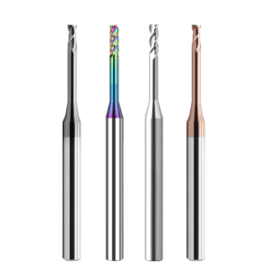
Last week, a long-time partner running a precision shop in California sent me a photo that told a familiar story. A 0.5mm small end mill had snapped clean inside an aerospace aluminum component less than two minutes into a deep cavity cycle.
In this micron-level game, the tool itself is rarely the only culprit. Usually, it’s a critical detail that was overlooked. As veterans with 15 years on the front lines of a China small diameter end mills factory, we know that even a radial runout of 0.0001mm or a slight dip in clamping force can scrap a thousand-dollar workpiece.
Many peers focus on unit price and material grade. They often ignore how microscopic edge geometry affects heat at high spindle speeds. We see shops struggle with length-to-diameter ratios and flute designs, especially in mold finishing. If your small ball end mill radius (R-angle) is off by more than ±0.002mm, your manual polishing time will double.
We didn’t write this to repeat textbook formulas. This is “hard-won wisdom” from 15 years of listening to spindles. From selecting substrates for HRC 55+ steels to reading coating colors, these are the battle-tested insights we use to help our Western clients solve their toughest problems.
In this industry, anyone can rough with a 1/2″ cutter. The real pros master these “sewing-needle” tools. So, in your shop, what’s the bigger headache: sudden tool breakage or those maddening tool-change marks?
Why We Emphasize Selecting Small End Mill Bits Based on Substrate Rigidity First
In micro-diameter cutting, rigidity is the bedrock. When a part fails, most guys instinctively tweak the RPM or feed. However, our teardowns show the root cause is usually the physical properties of the small end mill bits. When you work under 1.0mm, the lever effect amplifies even tiny deflections. This leads to edge chipping the moment the tool hits the material. We’ve seen too many shops try to save five dollars on a tool, only to embed a broken carbide tip into a five-thousand-dollar mold.
High-rigidity substrates suppress the high-frequency vibrations that kill stable feed rates. If the Young’s modulus of the tool material isn’t up to par, no amount of CAM optimization can fix the deflection inherent in high length-to-diameter ratios. This is why experienced engineers scrutinize the carbide composition before they even look at the coating.
Selecting Ultra-Fine Grain Carbide for Machining High-Hardness Materials
Standard carbide grades lack the integrity to hold a sharp edge when cutting the HRC 55+ steels common in Western markets. In our lab, we’ve seen that coarse grain structures look like jagged saws under a microscope. This leads to rapid thermal fatigue. For these jobs, we insist on ultra-fine grain tungsten carbide (0.2µm to 0.4µm). Only small diameter end mills of this caliber provide the hardness needed without sacrificing fracture toughness.
However, don’t blindly chase “hardness.” Excessive hardness makes a tool brittle. That is a recipe for disaster if your setup lacks rigidity. We usually trade off based on the shop’s equipment. If your spindle runout is tight, we suggest a higher cobalt content for toughness. If you need ultimate “red hardness” for high-heat cycles, we move to advanced powder metallurgy. Controlling this microstructure is our “secret sauce” for high-end European and American projects.
Avoiding the Low-Price Trap: Assessing Impact Resistance via Breakage Tests
Procurement teams are often tempted by cheap “imitation brands.” As a manager at a China small diameter end mills factory, I’ll tell you: the crudest but best quality test is the breakage test. We randomly snap finished tools to check deflection and fracture morphology. A high-quality substrate fracture looks fine-grained and metallic-gray. Low-cost tools made with recycled materials look dull, black, and granular. They will fail unpredictably on your machine.
We tell our B2B clients: don’t judge a tool by the first sample. Judge it by batch stability. Cheap tools often hide microscopic internal cracks. You won’t see them during a low-speed demo. But at high RPMs, thermal expansion causes these “invisible” defects to shatter the tool. We trust physical stress tests over glossy spec sheets. Only substrates that survive our impact tests earn a spot in a precision spindle.
Tailored for Complex 3D Surfaces: Key Geometric Parameters for Small Ball End Mills
When machining medical implants or optical molds, the biggest fear is “surface distortion.” At the very tip of a small ball end mill, the cutting speed is virtually zero. This makes geometric design unforgiving. We often see shops with perfect toolpaths produce parts that look like they were gnawed by a file. Usually, the relief angle at the tip lost its support at the micro-scale. The tool stopped cutting and started extruding.
The “soul” of a micro ball mill is center-point consistency and edge continuity. We pay obsessive attention to the “S-gash.” This determines if the tool actually cuts at its dead center. Without a clean S-gash, the center generates intense friction, leading to material annealing or “gumming up.” When selecting tools for 3D profiling, check the spherical envelope error under a microscope rather than just the tool length. It’s the only way to ensure consistent surfaces.
The Impact of Ball Nose Radius (R-Angle) Precision on Finishing
In mold finishing, “precision” means an allowance of 0.01mm or less. Here, the R-angle tolerance is the only thing that matters. We once helped a lens-mold client who had periodic dimensional errors. We found their ball mills fluctuated by ±0.01mm. At a microscopic level, that’s a massive ridge on the part. We insist on keeping R-angle precision within ±0.002mm. This ensures the curvature from multi-axis machining is seamless.
Extreme R-precision increases production costs, so you have to weigh the trade-offs. If you’re just clearing corners on a plastic mold, ±0.002mm is overkill. But if you’re working on mirror-finish steel, any asymmetry will be magnified 100x during polishing. Our advice: look at your final inspection criteria first, then work backward to find the right roundness grade for your small diameter end mills.
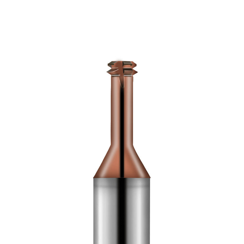
Minimizing Tool-Change Marks: Optimizing Cutting Edge Treatment
Tool-change marks are an engineer’s nightmare, especially on large, complex profiles. Our tests show these marks aren’t just path errors—they are caused by cutting force fluctuations from microscopic edge changes. We use a micron-level “Edge Preparation” process to fix this. By passivating (blunting) unstable micro-serrations, we make load transitions smoother during tool entry and exit. This extends stable cutting time and keeps surface texture consistent for hours.
We also recommend checking the dynamic balance of the edge. At high speeds, even tiny asymmetries cause “chatter marks.” We optimize our flute polishing to ensure chips evacuate smoothly from the small diameter end mills. This prevents “recutting,” where residual chips scar the finished surface. These refinements are invisible to the eye, but they are the difference between a scrapped part and a mirror finish when your spindle hits 30,000 RPM.
Runout: The #1 Killer of Small Diameter End Mills
In precision machining, “a miss is as good as a mile.” With micro-tools, this is an absolute law. When using small diameter end mills, runout (TIR) isn’t just a spec—it’s the difference between a tool lasting three minutes or three hours. Many veterans calibrate large fly cutters by “feel,” but in the micron world, an invisible wobble at high RPM creates massive centrifugal force. This instantly snaps the slender neck of your tool.
We’ve monitored high-speed spindles countless times and found that runout causes severe unevenness in the chip load. Imagine a two-flute micro mill: if runout is present, one edge is “fighting for its life” under double the load while the other is just rubbing. This imbalance triggers high-frequency chatter, leaving ugly marks on your finish and causing microscopic chipping. Before you even set your tool offsets, check the total rotational accuracy with a high-precision dial indicator.
Why Runout Over 0.005mm Instantly Destroys Micro Tools
You might think 0.005mm (5 microns) is negligible—it’s a fraction of a human hair. But in micro-machining, that deviation often exceeds your total programmed feed per tooth. Our tests show that when runout hits 10% of the tool diameter, tool life plummets. In work-hardening materials like stainless steel, runout causes the edge to impact the surface rather than cut it. These instantaneous shocks lead to fatigue and brittle fracture in the carbide substrate.
In our experience, this “instant failure” happens without warning. If you see spindle load fluctuating or hear a high-pitched “scream,” the edge is likely already gone. When handling expensive mold components, we’d rather spend ten minutes cleaning the taper and checking clamping torque than risk a 5-micron error. Micro-machining has zero margin for error; a single speck of dust in the spindle can kill your small diameter end mills.
Pro Tips for Shrink-Fit Holders and High-Precision Collets
To kill runout at the source, stop using standard ER spring collets for small end mill bits. We recommend shrink-fit or hydraulic holders. Their symmetrical design provides the rigidity and repeatability micro-tools need. Shrink-fitting essentially fuses the tool and holder into one monolithic unit. This near-perfect concentricity is a must for stable performance above 20,000 RPM.
If your budget is tight or you change tool sizes frequently, use high-precision, balanced collets. But remember: clamping length is everything. We often see operators “choke up” on a tool to avoid interference, or worse, not insert it deep enough. Our rule: insert the tool as deeply as possible without hitting the workpiece, and keep your spindle taper spotless. Any compromise in the tool-holding chain will be paid for by your expensive micro-cutters.
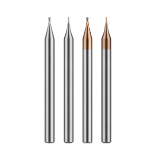
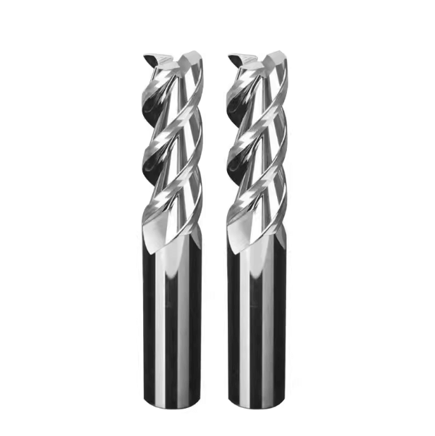
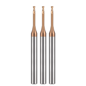
The Balancing Act: 2-Flute vs 4-Flute Small End Mills
Choosing the right flute count is a trade-off between chip evacuation and tool strength. A 2-flute small end mill has wide “valleys” (flute space) for chip removal. This is critical for soft metals and deep cavities. However, deep flutes mean a smaller core diameter, which reduces the tool’s bending strength.
In modern CNC setups, a 4-flute design boosts the cross-sectional area and rigidity, allowing for much higher feed rates. But at micro-diameters, 4-flute tools have almost no room for chips. We’ve seen many shops pursue “efficiency” with 4-flute tools without high-pressure coolant; the chips get trapped, the heat spikes instantly, and the tool welds itself to the part. Always evaluate your material’s chip formation and your coolant’s “oomph” before picking your flute count.
Preventing “Chip Welding” in Aluminum Slotting
When slotting 6061 or 7075 aluminum, “galling” or chip welding is your biggest enemy—not wear. In deep slots, aluminum becomes highly reactive under heat and pressure. If chips don’t get out, they weld into the flutes of your small diameter end mills. We recommend 2-flute designs with a mirror-polished finish. This “slick” surface lets centrifugal force eject chips instantly, preventing the re-cutting that snaps tools.
We also fine-tune the helix angle for these jobs. For deep slots, we increase the angle to act like an Archimedes’ screw, pumping chips out of the hole. But be careful: a high helix increases axial “lift.” If your fixturing isn’t rock-solid, you’ll get vibration. Our mantra for aluminum: the evacuation rate must be faster than the generation rate. If it’s not, no coating in the world will save your tool.
Stability in Hardened Steel: The 4-Flute Advantage
When machining steel over HRC 50, the script flips. Cutting forces are massive, and the thin core of a 2-flute tool will flex, causing dimensional errors. Here, we move to 4-flute small end mill bits. The extra edges distribute the load and—more importantly—massively increase vibration resistance. For finishing high-hardness molds, this stability is the only way to get a mirror finish.
Using 4 flutes lets you double your table feed while keeping a safe chip load. However, you must use a precise trochoidal milling (high-speed machining) strategy. This keeps the tool engagement angle low and prevents heat buildup in those tight 4-flute valleys. We pair these tools with nano-coatings and a “light and fast” strategy—shallow cuts at high speeds. It’s much safer and more stable than taking a deep, slow bite.
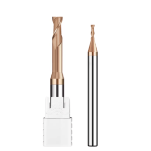
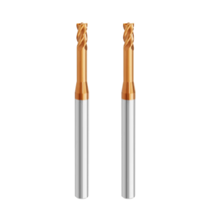
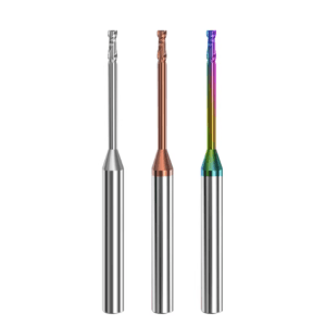
Coatings: The “Invisible Switch” for Tool Life
Coatings aren’t just for looks. As engineers in PVD (Physical Vapor Deposition) R&D, we know the coating’s microstructure is the “invisible switch” for tool life. We’ve tested two identical small diameter end mills where a slight change in “bias voltage” during coating created a 40% difference in wear resistance. At micro-diameters, if a coating is too thick, it dulls the edge; if it’s too thin, it fails under heat.
We formulate coatings based on chemical affinity. For high-hardness steel, we want nano-hardness and heat resistance. For aluminum or copper, we want surface “slickness” to stop sticking. At our China small diameter end mills factory, we perform post-coating polishing to remove microscopic “droplets” (tiny bumps) from the process. This ensures the tool stays smooth even when spinning at 40,000 RPM.
Nano-Coatings for Dry Cutting
Dry cutting is the gold standard for high-hardness mold steel. It prevents the “thermal shock” from coolant that causes micro-cracking. In these setups, the coating is a thermal shield. Our experience shows that aluminum-rich (Al) coatings (like AlTiN) form a protective aluminum oxide layer at high heat. This layer insulates the carbide, keeping the small diameter end mills’ “red hardness” intact.
A word of caution: dry cutting demands high anti-adhesion. If the coating reacts with the workpiece, the tool fails fast. We’ve solved this for many shops by adding silicon (Si) to the coating, which boosts toughness and heat resistance. It costs a bit more per tool, but for long, unattended runs, the stability is unmatched. Are you looking for the cheapest tool, or the highest yield per batch?
Medical Grade Strategies: Anti-Adhesion for Titanium
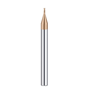
Medical parts—like bone screws or joints—are usually titanium (Ti6Al4V) or CoCr. These materials are “gummy” and don’t conduct heat. When using a small ball end mill for finishing, heat builds up right at the tiny tip. Standard coatings often fail after just a few parts due to Built-Up Edge (BUE). To fix this, we use specialized Diamond-Like Carbon (DLC) or ultra-smooth finishes.
This coating acts like “Teflon” for metal, preventing sticky chips from grabbing the edge. For high-value medical work, we want high hardness and low chemical affinity. By optimizing the coating’s “grip” on the ball tip, we’ve helped clients stop the micro-chipping that happens at the bottom of deep holes. In this industry, we recommend trading a bit of hardness for better lubricity—it’s the safest way to protect a five-hundred-dollar workpiece.
Mastering the Limits of Overhang Length
In micro-machining, overhang is the ultimate “watershed” factor for surface quality. When you’re on the shop floor forced to extend a tool to clear a fixture, you are battling the laws of physics. As a tool’s projection increases linearly, the deflection at the tip grows cubically. This geometric decay in rigidity is why small end mills often produce high-frequency chatter and “recoil lines” during high-speed cycles.
We’ve handled cases where clients used $100,000$ machine tools, yet their sidewalls still showed ripple patterns. The issue was simple: extended overhang changed the tool system’s natural frequency. We tell our peers: strive for the “bottomed out” state where the tool cannot be retracted any further into the holder. If the overhang is excessive, the tool’s momentary “yield” upon engagement will kill your pre-programmed cutting compensation. Don’t just drop the feed rate; re-evaluate your setup to minimize the gap between the spindle face and the cutting edge.
Adhering to the 3:1 Rule: Aspect Ratio and Stability
In our experience, the “3:1 Rule” is a lifesaver: keep the ratio of effective cutting depth to tool diameter within 3:1. At this ratio, a small end mill maintains maximum bending rigidity and suppresses radial runout. We compared 3:1 aspect ratio tools against 5:1 tools on the same hardened steel; the 3:1 tools had a fraction of the vibration and double the service life.
However, we aren’t dogmatic. Deep, narrow slots might require a “long-neck” tool at 8:1 or 10:1. If you must increase this ratio, you must sacrifice axial (Ap) and radial (Ae) depth of cut. For these long-reach small diameter end mills, we use a “light cut, fast feed” strategy. High RPMs and extremely low chip loads counteract the chatter. It’s slower material removal, but it saves the part from vibration damage.
Minimizing Chatter with Reinforced Neck Designs
When long overhangs are unavoidable, we use a “Reinforced Neck” design. Standard long-neck tools are uniform in diameter, but we incorporate a slight taper or stepped reinforcement at the root. This significantly increases the moment of inertia. This subtle geometric tweak dampens harmonic vibrations, keeping the cut “crisp” even at the bottom of a deep cavity.
We often discuss the balance between reinforcement and clearance with our North American clients. If the neck is too thick, it rubs the sidewall; too thin, and chatter ruins the finish. The best solution is a bespoke combination of unequal-pitch edges and a tapered neck. It costs more to manufacture, but it saves hours of troubleshooting on aerospace or complex mold projects. Have you ever had to choose between tool rigidity and part interference in those final millimeters of depth?
The Impact of Cooling Methods on Micro-Tool Performance
In precision work, temperature and chip evacuation are 80% of the battle. We often see shops “flood” the work zone regardless of the material. This is a mistake with small end mill bits. Because the edges are so delicate, “flood-style” cooling creates massive thermal gradients, causing “thermal cracking” in the carbide. Effective cooling isn’t just about being “cold”—it’s about dissipating heat and clearing chips without shocking the tool.
When milling hardened steel, we monitor the spindle load. Poor cooling lets heat build up, killing the tool’s “red hardness” and causing the material to weld to the edge. Note your spindle speed: at over 30,000 RPM, centrifugal force creates an air cushion that blocks liquid coolant from the cutting zone. In these cases, your lubricating medium must be able to “punch through” that air barrier to keep the tool alive.
Field Data: MQL vs High-Pressure Internal Cooling
We’ve run extensive tests comparing MQL (Minimum Quantity Lubrication) and high-pressure through-spindle cooling. For titanium or aerospace aluminum, internal cooling is great for flushing heat. However, internal channels in small end mill bits often weaken the tool’s core rigidity. This is why we recommend MQL for precision micro-work. MQL uses atomized synthetic lubricant to form a molecular film on the edge, drastically cutting friction.
On medical production lines, we’ve seen MQL-processed stainless steel parts show a 15% better finish than flood-cooled parts. The mist particles are finer and penetrate the microscopic gap between the edge and the workpiece. If your depth exceeds 5x diameter, you need through-spindle air or coolant for evacuation. It’s a budget vs. depth trade-off—high-end MQL and through-spindle setups aren’t cheap.
Air-Blast Machining: Preventing Chip Recutting
For finishing HRC 50+ steels, we almost always use a “Dry Air Blast.” At this hardness, chips are fine and brittle. If coolant makes them stick to the part, the small end mill bits will “recut” them. This repetitive crushing is the #1 cause of micro-chipping. High-speed photography shows that a powerful air blast doesn’t just cool; it expels chips from the zone instantly.
In narrow mold slots, we set the air nozzle at 45 degrees to the feed direction for a “broom effect.” We’ve seen many micro-tools snap because debris got trapped in the path. If you see smoke or smell burning, your air pressure is too low or your angle is off. In micro-machining, a “clean” zone is often more important than a “cold” zone. Are you still struggling with those tiny chips clinging to your tool tips?
The Logic of Fine-Tuning Feed Parameters
In micro-machining, Feed per Tooth (Fz) isn’t just a formula—it’s a balance of efficiency and tool life. Beginners often set the feed too low out of caution, which is a mistake. If your feed is lower than the small diameter end mill’s edge radius, the tool isn’t “cutting”—it’s “extruding” and “rubbing.” This creates intense friction and heat that kills the coating and causes thermal fatigue in the carbide.
Ideal feed means every edge “bites” the material and pulls a complete chip. We find the “sweet spot” by watching spindle load and chip morphology. If chips look like dust and the tool “whistles,” the feed is too light and the tool is skidding. If the sound is deep and the RPM fluctuates, the feed is too high. This requires a “feel” for the machine, as the optimal window is often just a few microns wide.
Redefining Parameters Based on Machine Rigidity
Don’t trust manuals blindly. Manual parameters are measured in perfect labs. When you put a small diameter end mill on a 5-year-old machine or a compact center lacking rigidity, those “book” settings become a death warrant. Spindle balance, rail repeatability, and vise clamping force all lower the load the system can handle.
When we support clients in Europe and North America, we start slow and “test” upward in 10% increments. In low-rigidity setups, we use “high RPM, shallow cut, moderate feed.” This light-but-frequent cutting compensates for the machine’s weakness. It’s more conservative than the manual, but it prevents the “batch-scrapping” disaster of a broken tool during an unattended run. Do you trust a printed chart or the sound of your machine?
Calculating “True Chip Thickness” to Stop Friction Wear
In Trochoidal milling or finishing with narrow radial engagement, “Chip Thinning” is the silent killer. If your radial depth of cut (Ae) is less than 50% of the diameter, the actual chip is much thinner than your preset feed. Without compensating, your small end mill bits stay in a state of frictional wear, which is why finishing tools often wear out faster than roughing tools.
We require our techs to calculate “True Chip Thickness.” The compensated feed is often much faster than the initial setting, which boosts efficiency and pulls heat away from the fragile edges. Just be careful: compensation has limits. You must respect the machine’s acceleration limits and controller speed. If the compensation makes the machine “jerk,” you’ll snap that micro-tool in seconds.
How to Select a Qualified Manufacturer of Small-Diameter End Mills in China
In a globalized supply chain, a reliable partner isn’t the one with the loudest ads; it’s the one with the most sound operational logic. As a China small diameter end mills factory with years of experience, we know that overseas clients fear the “blind box” of unpredictable quality. Many trading companies pose as manufacturers but rely on workshop-style subcontracting. When tool dimensions drift due to a 5-degree shift in shop temperature, your offset values for the first tool and the second tool will never match.
When vetting suppliers, ignore the monthly volume numbers. Ask about their climate-control standards and grinding wheel dressing frequency. A micro-tool facility must maintain a $\pm 1^\circ$C tolerance. For a 0.2mm cutter, thermal expansion of just a few microns ruins the geometry. When Western technical experts visit our floor, they don’t care about the office building; they listen to the acoustics of the grinding spindles and check the filtration of the coolant. These details are the true “birth certificate” of a quality tool.
Verifying 0.001mm-Precision Automated Inspection
In micro-milling, production is only half the battle; the rest is measurement. If a factory relies on manual micrometers or old-school projectors, your tool consistency is left to luck. We believe that without non-contact systems like Zoller or Helicheck—capable of 0.001mm precision—true process control is impossible. These systems detect micron-level distortions in the ball-nose R-angle without touching (and damaging) the fragile edges.
We mandate that every batch undergoes a full automated geometric inspection before shipping. We check more than just diameter; we scrutinize dynamic balance, flute smoothness, and chip channel roughness. At 40,000 RPM, a tiny asymmetry is a disaster. High-end inspection isn’t about “pretty data”—it’s about killing the risk of tool breakage before the box leaves our dock.
B2B Consistency: Ensuring Quality Across Ten Thousand Tools
For B2B clients, one great sample tool means nothing if the next ten thousand are different. We use rigorous raw material traceability and advanced grinding wheel wear compensation. Because wheels wear down physically during a run, the system must apply real-time compensation. Otherwise, the tool made at 8:00 AM will be different from the one made at 4:00 PM.
Our long-term clients value one thing above all: the ability to swap in a new tool without touching their CNC offsets. This trust is built on digital monitoring—from ultrasonic flaw detection of raw carbide to laser-etched serial codes on every shank. In micro-machining, consistency is the pinnacle of professionalism. Have you ever stood at a machine, frustrated because you had to re-calibrate everything for a new batch of the “same” tools?

Real-World Testing: Monitoring the “First Article” Process
Even the best simulation can’t replace the moment the spindle starts to turn. We tell our techs that “First Article Inspection” (FAI) isn’t just about the part—it’s about validating the entire system. Initial cuts expose latent issues like fixture “creep” or poor entry/exit points. A 10mm cutter might survive a bad entry; a small diameter end mill will not.
During the first part of a batch, stay at the control panel. Monitor the oscilloscope and load meter. For high-aspect-ratio tools, the wear on the first workpiece is your benchmark for mass production. If you see microscopic chipping after one part, drop your parameters immediately. Real-time monitoring is the only feedback that matters; it lets you find the “safety window” before a cascade of failures ruins your schedule.
Auditory Cues and Spindle Load Monitoring
In a CNC shop, your ears are often more reliable than your eyes. A healthy small end mill bit cutting high-hardness steel should sound crisp, continuous, and uniform—like a clean slice. If it sounds dull, muffled, or emits a high-pitched shriek, the tool has stopped cutting and started “galling.” This sound is the direct result of increased flank wear and surging resistance.
Watch your spindle load percentage. Micro-tools produce low absolute loads, but their relative fluctuations are huge. If the load curve shows “glitches” or spikes, you likely have a built-up edge (BUE) or a chipped tooth. Don’t wait for the machine to alarm out. If the load rises 5% to 10% or the sound changes, hit the reset button. A five-dollar tool isn’t worth a five-thousand-dollar spindle.
Preventive Replacement: Tool Life Profiles
To run unattended (lights-out) safely, you need a “preventive replacement” policy. We build life profiles by recording the exact part count and cutting time for every tool. If a tool’s “safe” life is 25 cycles on a stainless steel part, we pull it at cycle 20. This conservative trade-off is the cheapest way to avoid downtime and ensure every part in the batch stays within tolerance.
Don’t just track an aggregate total; segment the data into roughing, semi-finishing, and finishing stages. Finishing tools—those critical small end mill bits—should have the most conservative thresholds. Even slight wear here ruins the surface finish. Would you rather squeeze the last $0.50 of life out of a tool, or elegantly press “stop” to guarantee a perfect batch?