To be honest, after hosting so many engineers from Europe and North America at our facility, I’ve realized their biggest headache isn’t usually “how” to cut the part. It’s how to keep machines running at full capacity without grinding to a halt due to—that damned—aluminum chip entanglement.
Just last month, a long-standing North American client complained that their machine spindles kept triggering alarms while processing deep-cavity 7075-T6 aluminum housings. They were using “high-performance” tools, but the problem was simple: during heavy-duty roughing, the chip evacuation rate couldn’t keep pace with the cutting speed. Heat built up instantly, and the chips essentially welded themselves to the cutting edges.
We see this far too often. Many shops fall into a trap: they assume that as long as a carbide end mill for aluminum is sharp and the RPM is high, they are set. But what actually lets you sleep soundly during unmanned, late-night runs are the fundamental design details. Based on over a decade of manufacturing experience, we’ve distilled five core features you cannot compromise on when selecting aluminum end mill bits.
This isn’t just about pushing your Metal Removal Rate (MRR). It’s about the stability of your entire CNC machining process. If you’re struggling with “bird’s nest” chips or wondering why your 3 flute end mill for aluminum chips unexpectedly under high feed rates, it’s time for a fresh look at your tooling.
As a reputable aluminum CNC end mill supplier, we believe our job isn’t just selling tools—it’s minimizing your risk of breakage.
Ask yourself: Did your last tool fail because it lacked rigidity and snapped, or did poor chip evacuation cause the material to weld to the flute first?
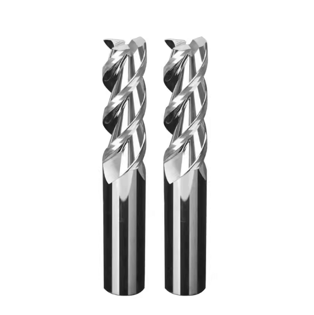
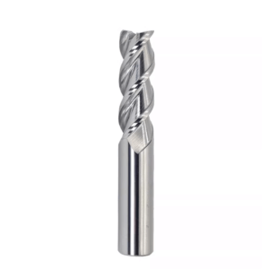
Why Are 3 Flute End Mills for Aluminum the Ideal Balance for Roughing?
In the workshop, we often see novices choose high flute counts for surface finish or stick strictly to two-flute cutters for “safe” evacuation. But in our 15 years of heavy-duty milling, the three-flute configuration is the undisputed “golden mean.”
Roughing is about removing maximum material in minimum time. This requires a tool that balances two conflicting goals: chip evacuation space and tool body rigidity. Aluminum chips are voluminous and sticky. If there isn’t enough room, the instantaneous formation of Built-Up Edge (BUE) will cause cutting forces to skyrocket.
Through extensive trials, we found that compared to 2-flute designs, a 3-flute end mill for aluminum allows for a larger core diameter while maintaining deep flutes. This significantly enhances bending resistance during deep side milling or slotting. When you push your feed rate beyond 0.15 mm/tooth, this structural stability becomes the difference between a precise part and a scrapped one.
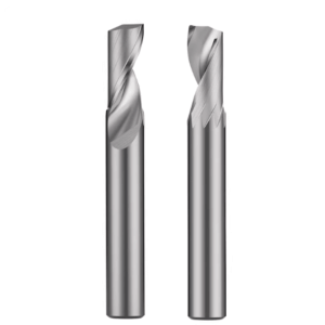
Avoiding the 2-Flute Rigidity Gap and the 4-Flute Nightmare
We recently ran a test for an automotive client machining aluminum castings. They were using 2-flute cutters for deep cavities, but at high RPMs, the tool tip vibrated severely, leaving chatter marks. While 2-flute tools have great chip space, their “core” is too thin. This lack of torsional rigidity leads to elastic deformation the moment the tool hits a hard spot or a feed fluctuation. For high MRR, 2-flute cutters often act as a “ceiling” on your productivity.
On the other hand, 4-flute tools are a chip evacuation nightmare for aluminum roughing. We’ve seen 4-flute cutters jam so fast in 6061 aluminum that the chips compress into a solid mass before you can even hit the E-stop. Unless you are doing very shallow finishing, a 4-flute tool simply cannot handle the “explosive” chip volume of aluminum. The 3-flute design offers the perfect margin for error: aggressive cutting like a 2-flute, with the stability of a multi-flute tool.
Asymmetrical Flute Design: Killing Vibration at High RPMs
Nothing unnerves a machinist like that piercing, high-pitched “screaming” sound. That noise is harmonic resonance, and it’s a tool-killer. Symmetrical tools, where flutes are spaced perfectly at 120°, are prone to triggering the machine’s natural frequency.
When we design a high-performance aluminum roughing end mill, we use Unequal Indexing. By disrupting the rhythmic regularity of the cutting cycle, we break the conditions needed for resonance to occur.
This asymmetrical geometry is a lifesaver for thin-walled parts. On a client’s 5-axis center, switching to unequal indexing allowed them to run at full speed through zones that previously required slowing down to avoid chatter. Beyond noise reduction, this maintains the dynamic balance of your spindle. An unbalanced tool at 20,000 RPM generates centrifugal forces that don’t just ruin the finish—they inflict chronic, expensive wear on your spindle bearings.
Technical Detail: Eliminating the “Scream”
We once helped an aerospace supplier machining a frame with a wall thickness under 2mm. The chatter was so violent it reverberated through the whole shop, leaving a “fish-scale” pattern on the walls.
We swapped their tool for a 3 flute end mill for aluminum featuring variable helix angles. That shriek immediately turned into a steady, low-frequency hum. This isn’t just about lowering noise; it’s about ensuring the release of cutting forces is no longer synchronized. By fine-tuning the phase angle of each edge, we provide “vibration compensation” directly at the spindle.
In real production, the superior tool isn’t just the hardest—it’s the one that runs stably and cuts quietly. If your shop is still deafeningly loud, ask yourself: is your tool design just a bit too “perfectly symmetrical”?
Specialized Flute Geometry: More Than Just a Standard Carbide End Mill for Aluminum
In the pursuit of the ultimate Metal Removal Rate (MRR), many engineers fall into a trap: they believe maxing out spindle speed and feed rates is the only answer. But in our decades of manufacturing experience, high parameters without a tailored flute geometry are just a recipe for disaster.
Aluminum alloys are highly ductile. Under high-speed cutting, the heat makes the material viscous and elastic—almost like a rubber band. When a standard tool takes a deep cut, forces concentrate in one spot, triggering high-frequency chatter. This doesn’t just ruin the finish; it kills your spindle bearings.
Our philosophy for high-performance aluminum roughing end mills is centered on “dissipating” these forces. We use a specialized geometric profile to change how chips form. For high-volume roughing, we always tell our clients to look at the micro-geometry of the edge. This structure segments wide chips without sacrificing tool rigidity. If you watch your machine’s load meter, you’ll see a far smoother curve at the initial engagement compared to a standard straight-flute tool.
The Decisive Role of “Wavy Edges” and Chip-Breakers
I remember a specific case with a North American aerospace client. They were machining large aluminum castings with standard flutes. Because the depth of cut was so aggressive, the chips were incredibly long—coiling around the end mill bits for aluminum like a massive “bird’s nest.” They had to stop every ten minutes to manually clear the spindle. It was a productivity killer and a safety hazard.
We swapped their tooling for a roughing end mill with a Knuckle Profile (wavy edge). The brilliance of this design is the staggered, offset teeth that physically sever long chips into small, manageable fragments. Suddenly, the “bird’s nest” turned into granules that looked like corn kernels. With high-pressure coolant, these fragments flushed away instantly. For a high-volume shop, this means more than a clean floor—it means hours of unattended machining time.
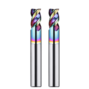
Mirror Polish: Letting Aluminum Chips “Skate” Out of the Flute
When tools start sticking, most people blame the coolant. In our experience, that’s usually just treating the symptom. Even with expensive synthetic fluids, if the flute interior isn’t perfectly smooth, aluminum will “weld” itself to the carbide under pressure. This is the dreaded BUE.
To solve this, we use a “Mirror Polish” process in our factory. We reduce the surface roughness of the flutes until they look like glass. This ensures chips encounter almost zero friction, gliding out as if they were on ice. This silky-smooth evacuation keeps heat from building up and delays chip adhesion, even during dry machining or MQL setups.
Why Non-Polished Flutes Fail the “BUE” Test
We once ran a side-by-side test with two tools: identical geometry, but one had a standard ground finish and the other was mirror-polished. Within thirty minutes, the non-polished tool had distinct silvery-white deposits in the flutes. These deposits changed the tool’s geometry, dulled the edge, and created more heat—a classic “death spiral” for a tool.
A polished flute isn’t for aesthetics; it’s the final line of defense for edge sharpness. We insist on this for every 3 flute end mill for aluminum we produce. If your flutes aren’t “slippery” enough, they become a safe haven for chips. Are your operators still scraping aluminum off the tool with a utility knife? If so, your flute finish is the problem.
The Truth About Substrates and Coatings: Extending Tool Life
In tool manufacturing, “harder” isn’t always “better.” We often see manufacturers cut corners by using general-purpose carbide grades (meant for steel) to grind tools for aluminum. It’s a mistake. Heavy-duty aluminum cutting requires specific properties. You don’t need extreme “red hardness,” but you do need incredible Transverse Rupture Strength (TRS). Without it, micro-cracks propagate the moment you hit an interrupted cut, leading to catastrophic chipping.
As a specialized aluminum CNC end mill supplier, we are picky about our base materials. Roughing is a series of high-frequency micro-collisions. If you only chase high cobalt content for toughness, you lose your edge retention. We use customized ratios that maintain hardness while arresting cracks through precise grain control. This “inherent resilience” is something you won’t see on a data sheet, but you’ll feel it when your machine is running under heavy load.
Choosing Micro-Grain Carbide Optimized for Aluminum
On our lines, we use a dedicated evaluation system for aluminum substrates. A client once came to us with frequent root fractures on their tools during deep-cavity slotting. Our lab found their generic micro-grain substrate couldn’t handle the axial tension from high helix angles.
We switched them to an ultra-fine micro-grain substrate developed specifically for non-ferrous metals. With about 12% cobalt and a specialized compaction process, this material absorbs the random impact loads of roughing. This determines the “micro-sharpness” of the edge. Under 500x magnification, generic tools look jagged; our aluminum-specific tools are perfectly linear. If your tools “chip out” before they actually wear down, your substrate isn’t meeting the demand for impact toughness.
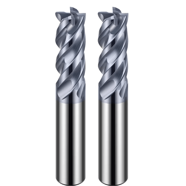
ZrN Coating vs DLC: Winning the War Against Silicon
Don’t just buy the most expensive coating. If you are machining high-silicon alloys like ADC12 or A380 die-cast, the silicon acts like sandpaper on the edge. In these cases, TiAlN is a disaster because the aluminum in the coating wants to weld to the aluminum in the part.
For standard alloys, ZrN is the “workhorse.” It has an incredibly low friction coefficient and stays chemically inert, making it a very cost-effective way to stop tool sticking.
However, for abrasive high-silicon aluminum or extreme RPMs, DLC is the king. It’s nearly as hard as a natural diamond, allowing it to shrug off abrasive erosion. In our tests, DLC-coated tools lasted nearly three times longer than ZrN in 12% silicon aluminum. But let’s be honest: if you’re just cutting 6061 with good coolant, ZrN or even an uncoated tool is usually all you need.
Data Spotlight: Preventing the “Chemical Pump” Effect
Our records show a massive gap in performance based on coating choice. In a continuous mill test on 7075 aluminum:
-
Uncoated Tool: Failed at 45 minutes (BUE caused dimensional error).
-
ZrN Coated: Lasted 180 minutes (consistent finish).
-
DLC Coated: Lasted over 400 minutes.
This happens because the right coating stops the “chemical pump”—the process where aluminum atoms diffuse into the carbide substrate. We’ve even solved European heat sink applications by controlling ZrN thickness to the micron level. A coating that’s too thick will actually dull the edge.
When you’re facing a “tool killer” material, are you picking the right shield, or just the most expensive one?
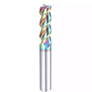
The Art of Geometric Angles: Combining Large Helix Angles with Robust Cutting Edges
In the heavy-duty roughing of aluminum alloys, geometric angles are never just about aesthetics. They are about striking a dynamic balance between cutting forces and chip evacuation. Aluminum might be softer than steel, but it possesses high instantaneous elasticity and a massive coefficient of thermal expansion. A single, uniform helix angle is rarely enough to handle this.
Through years of manufacturing, we’ve found that if the angle is too small, the entry impact slams directly into the machine spindle. If it’s too large, the axial “lift” increases, potentially pulling the tool right out of the holder. Navigating this trade-off is the core technical challenge in designing a high-performance aluminum roughing end mill. We favor a large positive rake angle paired with a specialized relief angle. This ensures the edge slices like a scalpel rather than crushing the metal. This reduces heat and prevents the material from softening and sticking.
How 35°/38° Variable Helix Angles Kill Vibration
We once helped a client running an older 3-axis mill with worn ball screws. Every time they tried side milling with a standard 35° tool, the whole machine emitted a deafening resonance. The system simply wasn’t rigid enough for the frequency. We swapped their tool for a 3 flute end mill for aluminum with a variable helix that alternates between 35° and 38°.
The logic is simple: we deliberately induce a “phase shift” in the cutting frequency. This disrupts the rhythmic vibrations before they can superimpose into a chatter storm. This “alleviates the load” on the machine. As the first edge exits at 35°, the second enters at 38°. This temporal offset dampens the spikes in axial and radial force. This support solution allowed our client to boost their feed rate by 40% on an old machine without a single hardware upgrade.
Enhanced Core Diameter: Preventing Breakage at High Feeds
In the hunt for the ultimate Metal Removal Rate (MRR), many operators push feeds to 0.2 mm/tooth or higher. This is where most “high-speed” cutters fail, snapping right at the tool root. Why? Because traditional tools sacrifice too much “core thickness” to make room for chips. In our labs, when the depth of cut (Ap) reaches 1.5x the diameter, shear stress at the root increases exponentially.
To fix this, we developed a tapered core design. It provides massive chip space at the tip but thickens progressively toward the shank. This “light-at-the-front, stable-at-the-back” architecture provides the torsional strength needed for high-feed roughing. We recently helped a die-casting client eliminate their “tool breakage anxiety” by simply increasing this core thickness by 15%.
Why Do “High-Performance” Tools Snap at 0.2mm/tooth?
We’ve seen many carbide end mills for aluminum on the market that look great because their flutes are incredibly deep. While this helps evacuation, it leaves a fragile cross-section. When the feed hits 0.2mm/tooth, the resistance exceeds the material’s fracture limit. Our destructive testing shows that tools prioritizing chip space to an extreme degree have 30% less bending resistance than reinforced designs.
Without a robust “skeleton,” those big flutes are just a house of cards. We incorporate subtle reinforcing radii into every tool to mitigate stress at the root. You might not notice it during routine jobs, but when you are trying to break cycle-time records, it’s the final line of defense for your spindle. Is your tool truly “tough,” or just “brittle”?

The “Invisible Criteria” for Choosing a Reliable Aluminum CNC End Mill Supplier
When we talk to technical directors in Europe and the US, their vetting process has moved far beyond “sample testing.” In 2026, a qualified aluminum CNC end mill supplier must be integrated into your entire process chain. A supplier who only hands you a box of tools and a sheet of generic speeds is failing you. The real competency is a “database” of solutions that translates into actionable productivity.
We position ourselves as “solution providers.” When we ship a batch of 3 flute end mills for aluminum, we include cutting strategies tailored to your specific machine rigidity and workholding. We can explain the performance shift between a CAT40 and an HSK63A holder, or help you optimize dynamic milling paths in your CAM software. The sale is just the beginning; the partnership is in providing proven parameters when you hit a vibration or finish defect.
Does Your Supplier Know Their Aluminum Grades?
Clients often ask: “How does your tool cut 6061?” We always ask back: “What’s the temper? Are you slotting thick plate or milling thin walls?” A professional supplier must understand materials science as well as tool grinding. If they don’t know why the “stickiness” of 5052 requires a different rake angle than the “brittleness” of 7075, they will only ever keep you at a “safe” speed, never an “efficient” one.
We deliver “digital twin” data. When we supply customized carbide end mills for aluminum to semiconductor equipment manufacturers, we provide the Tool Library files. This eliminates the trial-and-error phase for their engineers. This support, rooted in 15 years of industry data, is what separates a specialized manufacturer from a generic reseller.
Solving the “Second Batch” Problem: Total Consistency
“Why did the samples work, but the second batch started chipping?” This is the most common complaint in the industry. For a manufacturer, making one great tool is easy. Making the 1,000th tool identical to the 1st is the hard part. In aluminum machining, a deviation of just 3 to 5 microns in the edge geometry can cause tool sticking.
We use a “Total Lifecycle Consistency Management” system. Every four hours, we perform automated compensation and calibration on our grinding wheels. Every batch undergoes non-contact optical scanning. This ensures every tool exported shares the exact same “DNA.” In automated Western workshops, stability is more valuable than a one-time “hero” tool. We would rather sacrifice production volume than sacrifice uniformity. On a machine running at 3:00 AM, the slightest uncertainty can scrap a whole batch of parts. Do you have “hit-or-miss” tools in your warehouse right now? If so, you’re losing money on uncertainty.