When discussing high-efficiency milling of aluminum alloys, the fear that haunts machinists most isn’t gradual tool wear—it’s that heart-stopping “screeching” sound. The moment you hear it, you know exactly what’s happening: your aluminum end mill is recutting chips.
We’ve witnessed this scenario all too often while providing technical support to precision shops across North America. Imagine a five-axis machining center—worth hundreds of thousands of dollars—destroying a high-performance carbide end mill aluminum in less than ten minutes. The culprit? A tangled mass of aluminum “birds-nesting” that clogged the flutes. This isn’t just about losing a tool; it’s about the catastrophic surface scratches that turn a $5,000 aerospace component into scrap.
In our experience, chip recutting is the #1 silent killer of cycle time. Many machinists instinctively blame a “soft” coating or substandard carbide. However, as an aluminum CNC end mill supplier, our field-testing proves the root cause usually lies in overlooked process geometry. Especially during high-MRR (Material Removal Rate) cycles, if your aluminum cutting end mills aren’t matched to the specific alloy’s chip-evacuation needs, aluminum will fuse to the cutting edges like molten solder.
We have compiled the top 5 critical pain points we’ve resolved for Tier 1 suppliers. Stop sacrificing your feed rates for a “fake” sense of stability—here is how you actually fix the problem.
Why Doesn’t Your Aluminum End Mill Have Enough Chip-Evacuation Space?
In our diagnostics, we frequently find machinists opting for tools with larger core diameters to gain rigidity. For an aluminum end mill, this is often a critical misconception. Aluminum chips are voluminous and highly adhesive; if the cross-sectional area of the flute gullet is insufficient, these high-velocity fragments undergo secondary compression within the channel.
The fundamental purpose of chip evacuation space is to provide an “escape route.” Once this space is packed, cutting forces increase exponentially. The piercing whistling sound you hear is aluminum being forcibly crushed against the edges of the carbide end mill for aluminum. Rather than blindly increasing rigidity, re-evaluate the depth and geometry of the flutes to ensure every chip is carried away by coolant or air.
The Flute Count Trap: 4-Flute vs 3-Flute Aluminum Cutting End Mills
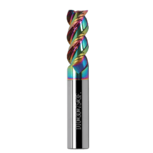
Last year, we supported a client machining 6061-T6 aerospace parts. They were struggling with a narrow cavity 3x deeper than the tool diameter and experiencing constant breakage. We found them running a 4-flute tool to get a better finish. While 4-flute end mills are standard for steel, in aluminum, they drastically reduce the chip-holding capacity per flute.
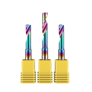
We recommended switching to a 3-flute aluminum CNC end mill. Although it has one fewer cutting edge, the chip evacuation volume per flute increased by nearly 30%. The breakage vanished, and they actually recovered efficiency by bumping the spindle speed. In deep slots, “space takes precedence over rigidity.”
Flute Polishing: Why We Insist on a Mirror Finish
As an aluminum CNC end mill supplier, we’re often asked: “Why do your flutes look like mirrors?” It’s not for aesthetics. Under a microscope, unpolished carbide flutes are riddled with grinding marks. For viscous aluminum, these marks act as “hooks,” inducing Built-Up Edge (BUE) where chips stubbornly adhere to the flute bottom.
Our testing shows that polished flutes reduce the friction coefficient by over 40%. Chips slide—rather than being squeezed—out of the channel. This attention to detail reduces heat and prevents the carbide end mill for aluminum from fracturing due to adhesion. If your flutes accumulate residue after minutes, the surface quality is substandard, regardless of your parameters.
Chip Accumulation Caused by Flawed Roughing Strategies
During the heavy-cutting phase, many shops reach a standstill because of conservative strategies. Machinists often apply a “steel mindset” to aluminum, thinking high RPM alone solves everything. But aluminum undergoes plastic deformation rapidly. If your aluminum end mill doesn’t cleanly shear the material, heat-expanded chips will encase the tool body like chewing gum. This BUE destroys tolerances and spikes spindle loads.
Success in roughing hinges on “chip morphology” rather than just chasing depth of cut. When performing deep cuts or large step-overs, you must account for the fluid-dynamic behavior of chips. If the geometric design of your aluminum cutting end mill cannot physically alter the form of these chips, your flutes will inevitably become “choked.”
Chip Control: Shattering Strands with an Aluminum Roughing End Mill
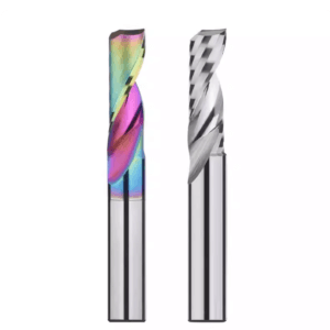
While troubleshooting for a client making large aluminum vehicle housings, the problem wasn’t efficiency—it was “bird’s nest” tangles of aluminum strands several meters long. These were dangerous and triggered collision alarms. We replaced their straight-flute tools with an aluminum roughing end mill featuring a wavy-edge (serrated) design.
This unique tooth profile creates physical fracture points, shattering ribbon-like chips into fingernail-sized fragments. While some worry about finish quality, in roughing, “evacuation safety is king.” Fragmented chips are easily flushed out by the conveyor. For unattended machining, this strategy is your ultimate line of defense.
Feed Rate Too Low: Don’t Be Afraid to Let Your Carbide End Mill “Run”
This is a common psychological pitfall: out of fear of breakage, professionals subconsciously lower the feed rate. For a carbide end mill for aluminum, an excessively low feed means the edge is “rubbing” rather than “cutting.” This friction generates massive heat, and since aluminum is highly conductive, that heat transfers to the tool tip, causing the material to reach its softening point and fuse to the tool.
We often say aluminum requires “brute force.” When you appropriately increase the chip load (feed per tooth), the chips carry away the majority of the heat, protecting the carbide substrate. We recently increased a client’s feed rate by 50% on 7075 aluminum; not only did tool life extend, but the BUE issue was completely resolved because the chips were being evacuated faster than they could heat up. Don’t let fear-driven parameters squander the potential of a high-performance aluminum CNC end mill.
The “False Sense of Adequacy” in Coolant and Chip Evacuation Pressure
When troubleshooting for clients, we frequently hear the same frustrated complaint: “I’ve cranked my coolant flow to the maximum, so why are chips still welding to the edge?” This is a classic case of “false adequacy.” Many operators assume that as long as there is a visible mist in the cutting zone, the cooling is sufficient. However, in high-MRR aluminum machining, the primary function of coolant isn’t just temperature control—it’s providing the kinetic energy to physically displace the chips. If your pressure is low, or if the nozzle is misaligned by even a few millimeters, those superheated chips fall right back into the path before the aluminum end mill completes its next rotation.
We contend that ineffective cooling is more dangerous than no cooling at all. It instills a false sense of security while the tool is actually failing. With ductile aluminum, if a chip isn’t forcefully evacuated within a fraction of a second of shearing, it instantly contracts and welds to the rake face of the carbide end mill for aluminum. This “secondary cutting” is the invisible culprit behind frequent tool breakage in many shops—a root cause that often remains elusive to the untrained eye.
The Coolant Barrier Surrounding Aluminum Cutting End Mills at High Speeds
When spindle speeds hit 15,000 RPM or higher, the rapidly rotating aluminum cutting end mill generates a powerful, invisible air vortex—an “aerodynamic barrier”—around the tool body. This phenomenon prevents standard low-pressure flood coolant from reaching the actual cutting edge; the fluid is simply flung away by centrifugal force. We often observe nozzles effectively “cooling the air” while the tool tip performs a dry cut. This is the primary catalyst for Built-Up Edge (BUE).
To breach this barrier, we advise abandoning the “scatter-gun” approach for adjustable, high-pressure directional nozzles. The optimal impact point must be precisely directed toward the tool’s relief groove at a 30° to 45° angle. As a specialized aluminum CNC end mill supplier, we’ve found that lubrication of the shear zone only happens when the kinetic energy of the jet exceeds the repulsive force of the vortex. Fine-tuning this angle is often more effective than upgrading to a more expensive tool material.
The Critical Role of Through-Coolant in Deep-Hole Machining
For deep holes or enclosed cavities, we follow a strict rule: utilize through-spindle coolant (TSC) whenever possible. We recently assisted a North American aerospace manufacturer machining wing connectors—specifically, a blind hole four times the tool diameter in depth. Using external cooling on a standard carbide end mill for aluminum, the chips turned into a viscous, porridge-like slurry at the bottom, causing cycle times to balloon.
Once we switched them to a specialized aluminum cutting end mill with a central through-coolant outlet, the results were dramatic. The “inside-out” flushing force aggressively drives every chip up the helical flutes and out of the exit. Data showed that at the same RPM, evacuation efficiency improved by 200%, and the hole bottom went from a matte finish to a mirror-like shine. In deep-hole applications, through-coolant is a vital lifeline that prevents the aluminum CNC end mill from being buried in superheated debris.
Coating Conflicts: Avoiding Materials That “Weld” Chips to the Tool
In our lab, we often see a regrettable mistake: machinists seeking “extra hardness” for their aluminum end mills choose high-end coatings designed for stainless or mold steels. Aluminum machining operates under different physics. Due to its reactive nature, aluminum has a high affinity for other metals at elevated temperatures. If you select a coating with a chemical attraction to the workpiece, that thin film acts as a “flux,” causing chips to weld firmly to the edge.
The role of a coating in aluminum machining isn’t “hardness”—it’s “lubricity.” If there is chemical affinity, edge chipping from secondary cutting is inevitable. As a veteran aluminum CNC end mill supplier, we know a truly high-performance tool must microscopically sever any chemical bond with the aluminum molecules. This ensures the edge remains sharp and free of debris even under extreme friction.
Why AlTiN is the Natural Enemy of Aluminum End Mills
The most common error we correct is the use of AlTiN (Aluminum Titanium Nitride) on aluminum cutting end mills. Because AlTiN contains aluminum, the heat of the cut triggers an “affinity reaction” with the workpiece. Like attracts like; the chips instantly weld to the tool tip. We analyzed a failure for a heat-sink manufacturer who thought AlTiN’s heat resistance would help with high RPMs. Instead, the chemical attraction clogged their flutes in less than sixty seconds.
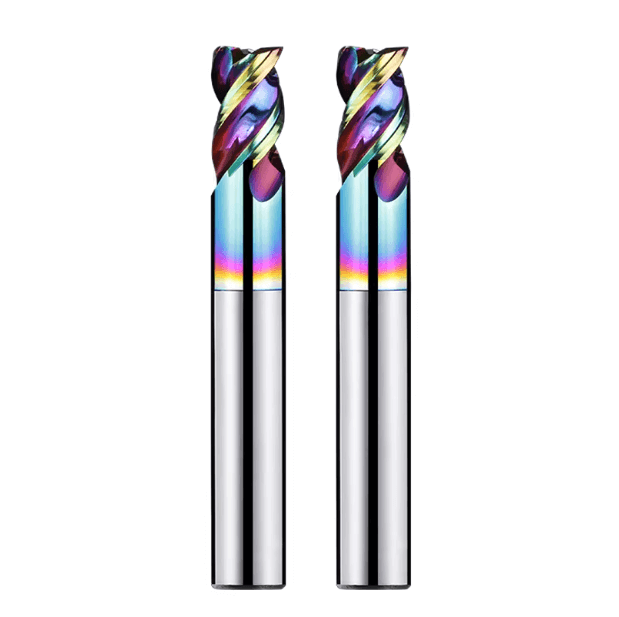
We consistently recommend ZrN (Zirconium Nitride) or DLC (Diamond-Like Carbon) coatings. Our lab tests prove that ZrN has an extremely low coefficient of friction against aluminum and, being aluminum-free, eliminates thermal adhesion. DLC is even better—it’s exceptionally hard and slick, allowing chips to slide across the carbide end mill for aluminum at astonishing speeds. While the initial cost is higher, the ROI is found in the hours of downtime saved by eliminating BUE.
Uncoated vs Coated: Real-World Testing in Our Laboratory
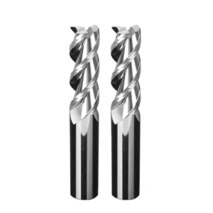
We recently ran a head-to-head test: a low-cost, commercially available titanium-coated tool versus our proprietary, highly polished, uncoated (Bright Finish) aluminum CNC end mill. The results defied expectations. Machining 5052 aluminum, the inferior coated tool failed after 15 minutes due to BUE and surface roughness. In contrast, our uncoated tool—benefiting from ultra-fine polishing and a pristine edge—cut smoothly for over 40 minutes.
The takeaway: if you are on a budget, it is far wiser to opt for a high-quality uncoated tool with a superior base material and precision-treated edges than a cheap coated tool. High-quality aluminum cutting end mills maintain a smaller edge radius, minimizing resistance and heat. However, this only works if the flutes have a mirror-finish polish. In many cost-sensitive scenarios, we recommend tools in their natural carbide state, as it allows you to monitor chip flow with total clarity.
Chip Evacuation “Dead Zones” in Toolpaths
After resolving thousands of real-world machining cases, we have reached a definitive conclusion: even if you are equipped with the world’s most advanced aluminum end mill, an ill-conceived toolpath makes it impossible to escape the dreaded “recutting” of chips. Many machinists still rely on traditional “slotting-style” paths—where the cutter is forced forward in a full-width engagement (100% Ae). In these paths, chips are trapped on both sides of the tool; with no lateral escape route, they are compressed upward, causing spindle loads to spike and heat to build instantly.
We view toolpath design as the management of the “chip evacuation window.” Whenever a path features sharp 90-degree corners or dwells too long in a narrow slot, chips accumulate and create a “dead zone.” A skilled programmer mentally simulates the trajectory of chip ejection before hitting cycle start. If your path fails to provide sufficient clearance for your carbide end mill for aluminum, even the highest-pressure coolant won’t save a process doomed by a flawed toolpath.
How Dynamic Milling Extends the Lifespan of Aluminum Cutting End Mills
To enhance machining stability, we have always been staunch advocates of Dynamic Milling (also known as Trochoidal or Cycloidal Milling). Traditional methods subject aluminum cutting end mills to severe radial shock. Dynamic Milling, however, maintains a constant angle of engagement, ensuring the radial depth of cut (Ae) remains low and stable. We recently helped a client machining 6061 aluminum plates by replacing their full-slotting strategy with a dynamic path at 10% Ae. The result was a 3x increase in feed rate (F) and a tool life extension of a full work shift.
The core advantage here is the physical “evacuation window.” Because the aluminum CNC end mill is not fully enveloped by the material, each cutting edge spends more than half of its rotation in a “no-load” state. This interval allows chips to be completely ejected by centrifugal force while allowing coolant to hit the edge directly. For shops chasing maximum MRR, this constant-load strategy is the best way to unlock the potential of high-performance carbide end mills for aluminum.
Corner Cleaning and Retraction: Preventing Failure at the Bottom of the Hole
In “Rest Machining” (corner cleaning) or deep blind holes, the most critical moment is the retraction phase. We’ve seen countless aluminum cutting end mills snap exactly when the tool finishes its pass and lifts. Why? Because residual chips at the bottom of the hole get re-entangled. If your retraction is a strictly vertical “dead-lift,” the tool tip will almost certainly collide with un-evacuated chips.
To fix this, we recommend an “Arc Out” or helical retraction logic. Before the tool stops its lateral motion, it should execute a small arc away from the wall. This ensures the edge is fully disengaged before the rapid vertical lift. As a specialized aluminum CNC end mill supplier, we’ve found this subtle tweak significantly reduces flank wear. Don’t underestimate this millisecond-long motion; it ensures your carbide end mill for aluminum exits the zone under pristine conditions, rather than struggling through a pile of “old chips.”
We Are More Than an Aluminum CNC End Mill Supplier—We Are Your Partner
In high-efficiency aluminum milling, the tool is only half the equation; the other half is chip evacuation logic. No matter how premium your aluminum end mill is, if you overlook gullet space, coolant momentum, or toolpath science, tool breakage is inevitable. As an aluminum CNC end mill supplier at the forefront of the industry, our mission isn’t just to sell carbide—it’s to help you find that “sweet spot” where efficiency and tool life intersect.
We share these insights so you can break free from the “it’s a bad tool” mindset. Instead, look at the color and shape of your chips the moment they fly off the edge. In today’s high-pressure market, preventing one instance of unplanned downtime is worth far more than saving a few dollars on a cheap cutter.
Actionable Advice: Chip Evacuation Troubleshooting Checklist
If you are facing a broken aluminum end mill or a marred surface finish right now, use our internal checklist for a rapid diagnosis:
-
Machining deep cavities or closed pockets? Check if you’re using a 4-flute tool. Switch to a 3-flute aluminum CNC end mill and verify that the flutes have a mirror-polished finish to prevent adhesion.
-
Chips tangling around the spindle? Introduce an aluminum roughing end mill with chip-breaking features. Also, check your feed rate; if it’s too low, you’re likely generating “heat-wrap” instead of clean chips.
-
Seeing “welded” aluminum on the edges (BUE)? Verify your coating. Avoid AlTiN; switch to a ZrN-coated or high-polish uncoated carbide end mill for aluminum. Bump up your coolant pressure to break through the high-RPM wind resistance.
-
Breaking tools during retraction? Review your paths. Incorporate an “Arc Out” motion and use Dynamic Milling to keep your radial load constant.
Every variable matters—from machine rigidity to the silicon content of your alloy (6061 vs. 7075). As fellow professionals, we’re happy to look at your specific part drawings or cutting parameters. We’d rather collaborate on a solution than see another high-performance aluminum cutting end mill go to waste.
So, is your current bottleneck in managing chip morphology, or are you struggling with coolant delivery at 15,000+ RPM? Let’s talk about it.