Just last week, we walked into a major mold shop and saw a familiar, frustrating scene. A high-precision 5-axis machine sat idle. Spindle-mounted, an expensive carbide end mill had its cutting edge chipped into a jagged mess. The operator stood by, staring helplessly at a scrapped mold steel workpiece.
We have seen this scenario far too many times over the last fifteen years.
At our core, we do more than just sell tools. We dive into the trenches to solve real machining challenges. We know that when you’re cutting high-hardness materials, a chipped steel end mill isn’t just a tool failure. It’s a broken cycle, ruined surface finish, and often a scrapped batch of expensive mold steel.
Many shops instinctively blame tool quality. However, when we bring in our diagnostic gear to check cutting parameters, tool paths, and chip evacuation, we invariably find “invisible killers” lurking in the details.
Working with top-tier mold manufacturers across the U.S. and Europe, we’ve found that recurring chipping usually points to a few specific technical pain points. Whether you’re using roughing end mills for steel for heavy stock removal or finishing a cavity to micron-level precision, the logic is the same. Chipping is the physical manifestation of thermal shock, uneven mechanical loads, or a collapse in system rigidity.
If you’re tired of seeing broken carbide fragments on your machine bed, this guide is for you. We’re locking the textbooks away. Let’s talk candidly about the real-world shop floor “catastrophes” and the battle-tested strategies we use as an end mill for mold steel manufacturer to keep your machines running.

Speed and Feed Mismatch: Why Your Carbide End Mill Can’t Handle the Heat
There’s a common myth in the shop: “If I buy the most expensive tool, I can run it however I want.” That’s a fast way to kill a tool. A carbide end mill is essentially a ceramic. It’s incredibly hard and wear-resistant, but it’s also brittle.
When your cutting speed (SFM) and feed rate are out of sync, the edge doesn’t shear the metal smoothly. Instead, it suffers chaotic vibrations. This mismatch creates uneven thermal stress, leading to coating delamination and substrate fractures.
When we optimize a line, we always look at the chips first. If they are scorched black or distorted, the heat isn’t leaving with the chip—it’s soaking into your tool. This heat softens the edge instantly. If your coolant hits that hot edge unevenly, the resulting thermal shock will chip it every time. In high-stakes mold work, we always trade a bit of theoretical speed to find that “sweet spot” where heat and toughness balance out.
Over-Aggressive Chip Load in Roughing End Mills for Steel
The biggest “sin” we see is cranking the feed per tooth (IPT) just to meet a deadline. When using roughing end mills for steel for heavy stock removal, it’s tempting to push the tool to the limit. But carbide has a finite ceiling.
If the chip thickness exceeds the flute’s capacity, the chips compress inside the tool. This internal pressure is immense. It will literally “blow out” the most fragile part of the tool: the tip.
We recently helped a client machining large structural brackets. They were full-slotting with a high-performance rougher at an aggressive feed. The tool snapped before the first pass was done. We dialed the feed back by 20% but increased the depth of cut. By using the full length of the flute to distribute the load, we actually finished the job 30% faster because we stopped breaking tools and resetting offsets. Respect the material’s toughness, and your tools will respect your deadlines.
The Hidden Danger of Low SFM on Hardened Steel
Everyone knows high speed burns tools. But did you know running too slow can be just as deadly? When machining hardened steel, if your SFM is too low, the edge doesn’t “cut”—it “plows.”
This creates massive radial pressure, causing the carbide end mill to undergo microscopic deformation. Even worse, low speeds lead to Built-Up Edge (BUE), or tool adhesion. When these tiny bits of cold-welded metal finally snap off, they take a chunk of your carbide edge with them.
We see this a lot with guys transitioning from carbon steel to mold steel. They use low RPMs out of habit, hear a dull “hum,” and then a loud crack. If your tools are chipping at low speeds, try bumping your RPM by 15-20% (if your setup is rigid). You’ll hear the sound change from a “gnawing” crunch to a smooth “hiss.”
Insufficient Rigidity: The Silent Killer for End Mills Machining Steel
Before the machine alarm sounds, a lack of rigidity is already killing your tool. Machining steel is a “head-to-head” battle. The winner isn’t just the tool; it’s the entire system—the spindle, the holder, the fixture, and the workpiece.
If there is a single weak link or too much overhang, the tool won’t glide; it will “bounce.” This high-frequency micro-vibration, or chatter, is lethal. It induces stress fatigue, causing your steel end mill to shatter long before it wears out.
Our first move on the shop floor is rarely checking the G-code. We check the vise and the spindle. We often find an aging vise or backlash in the axes. Even a tiny “deflection” disrupts your chip load. If you see chatter marks on your part, don’t just slow down—check your structural integrity. That is the “bedrock” of tool life.
Deflection Issues with Long-Reach End Mills for Mold Steel Machining
As an end mill for mold steel manufacturer, we know deep cavities are a nightmare. You need long-reach tools to get into those pockets. But remember: if you double the overhang, you don’t just double the flex—you decrease rigidity exponentially.
In hardened mold steel, a long tool acts like a slender spring. Under load, it deflects (bends) away from the cut, then snaps back. This radial runout is the primary reason long-reach tools chip.
We once solved a die-casting mold issue by switching from a standard long-shank tool to a tapered-shank design with a relief cut. It cost more upfront, but the tapered support killed the deflection at the tip. Pro tip: Never use a slender shank if a thicker one fits, and never compromise on overhang. Even 5mm less reach can save your cutting edge.
Tool Holder Runout and Its Impact on Steel End Mill Life
Your tool holder is the only bridge between the machine’s “soul” and the tool’s “body.” We’ve found that a tiny runout of just 0.01mm (0.0004″) is enough to kill a tool.
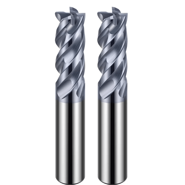
Think about a 4-flute carbide end mill. If the holder has 0.01mm runout, one flute is slamming into the metal while the opposite flute is “cutting air.” This imbalanced load causes that one overworked flute to fracture almost immediately.
If you’re struggling with tool life, ditch the old ER collets. Switch to heat-shrink or hydraulic holders. In our tests, moving from 0.015mm runout to 0.003mm doubled the tool life instantly. It’s not magic; it’s just uniform loading. Before you blame the tool maker, put a dial indicator on your shank. The data doesn’t lie.

Improper Chip Evacuation in Roughing End Mills for Steel
On a heavy-duty shop floor, metal chips are more than just waste—mishandle them, and they become a “death sentence” for your tooling. We often say that great machining isn’t just about how you cut metal away; it’s about how fast you get the hot chips out of the way. This is critical when using roughing end mills for steel. With high Metal Removal Rates (MRR), the volume of chips generated is staggering. If your evacuation path is blocked, chips pack into the flutes. This creates massive lateral pressure, leading to uneven stress and catastrophic tool failure.
When we visit clients, we don’t always need to look at the controller. We can hear the problem. An irregular “clicking” or “crunching” sound from the spindle usually means the tool is re-cutting its own chips. To protect your steel end mill, you must maintain a dynamic equilibrium: the higher the cutting force, the faster the chips must leave. Once chips soften under high heat and stick to the edge, your tool geometry is compromised. Spindle load spikes follow instantly. In our experience, your chip evacuation strategy is often more important than your actual cutting speed.
Re-Cutting Chips: The Fastest Way to Destroy a Carbide End Mill
Re-cutting chips is, without question, the fastest way to kill a carbide end mill. When steel chips fail to exit the zone and get pulled back between the workpiece and the rotating edge, they create extreme impact loads. This force far exceeds normal cutting resistance, causing microscopic fracturing in the carbide substrate. We often see chipping on the relief surfaces or secondary edges—classic signs of “rebound” damage from recirculating chips.
To stop this, we strongly recommend a through-coolant system whenever possible. High-pressure jets blasting from the tool tip provide the kinetic energy needed to flush chips out of deep slots. If you don’t have through-coolant, a powerful air-blow is your final line of defense. We once helped a client machining 4140 alloy steel who was struggling with short tool life. By switching from a side-spray to a high-pressure air purge, we reduced tool chipping by 60%. When cutting steel, keeping the zone “clean” is paramount.
Flute Design Secrets for Better Steel Chip Flow
As a manufacturer, we know flute design is what separates a mediocre tool from a high-performance one. Many of our peers fixate on large helix angles for a “lighter” cut and better finish. However, in heavy steel machining, a large helix can create a “suction effect” that pulls chips toward the tool root, causing packing. Through extensive trials, we’ve found that asymmetrical flute spacing is much more effective. It disrupts the evacuation rhythm and prevents chips from forming continuous, “snake-like” tangles.
In our optimization process, we apply a mirror-polish treatment to the flute bottoms. This minimizes friction, ensuring chips slide out the moment they are formed rather than sticking due to heat. Here is a trade-off to consider: if you are a mold steel manufacturer looking for maximum reliability, a slightly smaller helix angle paired with unequal spacing is often smarter than chasing the steepest angle. We manufacture our tools to ensure every chip has a clear, designated “escape route.”

Thermal Shock from Inconsistent Cooling on End Mills for Steel
In CNC programming, coolant is often seen as a “cure-all.” However, we see countless steel end mills scrapped specifically because of how they were cooled. While carbide is incredibly hard, it hates drastic temperature swings. When a cutting edge hits 800°C and is immediately quenched by an unstable coolant flow, it creates massive tensile stress. This “thermal shock” is a silent killer that causes high-performance tools to fail prematurely.
We’ve seen many operations where the nozzle is slightly misaligned or chips block the flow. This creates a “hot-and-cold” cycle that induces microscopic thermal cracks on the coating. Once these cracks hit the substrate, the edge becomes as brittle as glass. It will chip or spall the moment it hits any resistance. When machining steel, you have two logical choices: either fully submerge the tool in a flood of coolant, or go completely dry to maintain a constant, stable temperature. The worst thing you can do is “sporadic” cooling.
Why “On-and-Off” Coolant is Worse Than Dry Machining
Here is a hard-won conclusion: in many high-hardness applications, dry machining is actually safer for your carbide end mill than erratic wet machining. During continuous dry cutting, the tool tip reaches a high temperature but settles into a state of thermal equilibrium. In contrast, intermittent cooling shocks the carbide with internal stress several times greater than the actual cutting load.
When we analyze failed tools, we look for fine lines running perpendicular to the cutting edge—that’s thermal fatigue. Once those cracks form, impact resistance plummets. Even advanced heat-resistant coatings can’t stop the physical damage of rapid expansion and contraction. If we see a client with low coolant pressure or “dead zones” in their nozzle layout, we often recommend they forgo liquid cooling entirely. It sounds counterintuitive, but process stability extends tool life much better than inconsistent cooling.
Air Blow vs Flood Coolant for High-Speed Steel End Mill Applications
Why do we tell clients to “turn off the pump and turn on the air” for steels over 40 HRC? At high spindle speeds, centrifugal force slings low-pressure coolant away from the tool, creating an “air curtain” that prevents liquid from ever reaching the edge. A powerful air stream, however, provides a consistent cooling medium without the shock. More importantly, it physically blasts chips away. For steel end mills, a dry, stable environment allows the tool coating’s “self-lubricating” properties to actually work.
We once tested this for a client machining P20 mold steel. With liquid cooling, the tool lasted only two hours before micro-chipping. After switching to a high-pressure air blow, the same tool ran smoothly for five hours. While liquid cooling has its place, airflow is generally superior for preventing chip re-cutting and maintaining thermal stability in high-speed milling. Our recommendation: for high-hardness materials in tight spaces, prioritize air cooling combined with Minimum Quantity Lubrication (MQL). It’s often the best way to protect your investment.
Material Hardness Surprises for End Mill Manufacturers in the Mold Sector
In mold making, we don’t fear complex blueprints; we fear the “landmines” hidden inside the steel. As a long-standing end mill for mold steel manufacturer, we know that even a single block of pre-hardened steel can have “hard spots.” These metallurgical variations between the core and the surface are often caused by uneven heat treatment. They are the primary culprits behind sudden, unpredicted tool chipping. When your tool hits one of these spots at a constant feed, the cutting resistance surges instantly, pushing the carbide’s bending strength to its breaking point.
We often see chipping occur the exact moment the material property shifts. This uncertainty is why we build “safety margins” into our programming rather than blindly chasing maximum efficiency. If your cutting sound suddenly becomes sharp or you see a shower of sparks, you’ve likely hit a hard spot. At that point, complaining about material quality won’t save your part. You need tougher geometries and adaptive toolpath strategies to survive these “hard shocks.”
Dealing with Hard Spots in Pre-Hardened Mold Steel
When you hit a vexing hard spot, don’t engage in a head-on collision. Instead, “dissipate the force” by optimizing your toolpath. We recently helped a client machining 718H mold steel by switching them from linear slots to a trochoidal milling pattern. This dynamic path reduces the tool’s engagement angle. When the steel end mill hits an area of extreme hardness, the edge has the space and frequency it needs to shed heat and relieve stress. It adds a bit of programming complexity, but it’s the most cost-effective way to protect expensive, high-aspect-ratio tools.
Here is a veteran tip: if you feel the material is harder than expected, reduce your feed per tooth—not your spindle speed. In high-hardness zones, maintaining surface speed uses shear heat to locally soften the material. Too much feed, however, will simply crush the cutting edge. We train operators to watch the spindle load meter for subtle fluctuations. Learning to intervene with the feed override is what separates a master technician from an ordinary operator. It’s the best “old-school” method for extending tool life.
Entering and Exiting the Cut: The Moment of Maximum Risk
The most dangerous moment in machining mold steel is the split second the tool enters or exits the part. Over 40% of chipping incidents happen at these two points. Upon entry, the chip thickness jumps from zero to full load instantly. This “shock load” is brutal on brittle carbide edges. At the exit, if the path is poor, the remaining thin wall of steel can snag the edge like a hook. This creates reverse tensile forces that tear away both the coating and the carbide substrate.
To fix this, we strongly recommend Arc Entry (or “Roll-in”) techniques. By entering the steel with a helical or tangential arc, cutting forces build up gradually. Similarly, use tangential exits or decelerate at the end of a cut. We once helped a shop that was scrapping a tool every three parts. By simply switching to an Arc Entry, they reached ten parts per tool consistently. This meticulous attention to detail is what defines a seasoned machining engineer.
Summary Checklist: How We Stop Steel End Mill Chipping on the Shop Floor
Tool chipping is never an isolated quality issue; it is a “distress signal” from your machining system. When a carbide end mill shatters, don’t just grab a new one and hit “Cycle Start.” You’ll likely just repeat the mistake. After fifteen years in this business, we’ve learned to treat every failure as a data point for optimization.
To help you troubleshoot at the machine, we’ve condensed our protocol into this 5-point checklist. This is the exact process we follow as an end mill for mold steel manufacturer when we walk onto a client’s shop floor.
Quick Machine-Side Troubleshooting Checklist
-
Check Physical Runout If one specific flute always chips first, check your runout. Use a dial indicator on the shank and the flutes. Anything over 0.01mm (0.0004″) is a massive risk in steel. Switch to shrink-fit or hydraulic holders to equalize the load across all edges.
-
Evaluate Chip Load (Feed Per Tooth) If you see mechanical crushing on the tool tips during heavy roughing, your feed is too high. Reduce your IPT or switch to a dedicated roughing end mill for steel. Carbide has limits; don’t exceed the flute’s carrying capacity.
-
Verify Chip Evacuation Hear a “clicking” sound in a deep cavity? Your chips are packing. Increase internal coolant pressure or blast it with high-force air. Recutting chips is tool suicide. Clear them the instant they form.
-
Monitor Thermal Balance See fine, vertical cracks on the edge? That’s thermal shock. Shut off the coolant and go dry or use MQL. In hard steel, a stable high temperature is much safer than “on-and-off” cooling cycles.
-
Optimize Entry/Exit Chipping at the start or end of the program? Check your toolpath. Replace linear entries with arcs. Reduce the feed rate as the tool exits the material to avoid the “snap” of instantaneous impact.
Concluding Remarks
There is no “universal formula” for machining steel. Every material heat, every machine spindle, and every fixture setup changes the game for your end mills for steel.
We love hearing real-world feedback. If you are struggling with a high-toughness alloy or a complex mold geometry, let’s talk. Send us your parameters, material specs, or program screenshots. Often, the fix is just a minor tweak to a toolpath or a subtle change in flute geometry.
Do you have a challenging blueprint or a “nightmare” material on your desk right now? Let’s look at the force dynamics together and find the right tool for the job.