In our experience providing batch machining solutions for aluminum components to clients in Europe and North America, we frequently encounter a recurring problem: even when using high-quality CNC end mills, aluminum machining often suffers from issues such as chip clogging, severe material adhesion (“tool sticking”), and rough surface finishes. We’ve repeatedly worked with clients to fine-tune machining parameters, only to find that the root cause often lies not in the settings but in the fact that the tool’s geometric design is simply not suited for aluminum.
For instance, a client attempted to machine 7075 aluminum alloy using standard HRC55-rated CNC end mills. The result was rapid tool wear, difficulty in chip evacuation, and a surface finish far below expectations. After on-site analysis and tool modifications—specifically adopting an aluminum-specific end mill and adjusting the cutting edge and helix angles—chip evacuation became smooth, machining precision improved, and production efficiency increased by over 20%.
Through these real-world cases, we’ve realized that aluminum machining imposes specific demands on tool geometry: sharp cutting edges, large helix angles, and wide, smooth flutes for effective chip evacuation—all while maintaining sufficient tip strength for high-speed aluminum machining. Even high-precision tools produced by specialized CNC rough end mill factories in China can struggle to maintain consistent performance if their geometry isn’t optimized for aluminum.
Every challenge we solve deepens our understanding: tool geometry isn’t just a collection of parameters—it’s the result of ongoing validation and optimization through practical application. When working with various aluminum alloys and machining conditions, have you experienced similar difficulties with tool efficiency and chip evacuation?

Why Standard CNC End Mills Perform Poorly
In our extensive experience machining aluminum alloy parts, we’ve noticed that many standard end mills perform poorly in actual production environments. This is especially true for high-speed aluminum operations, where end mills designed for steel often struggle with chip evacuation and cutting stability. Even after adjusting feed rates and spindle speeds based on part geometry and cutting depth, the underlying problems often persist. Over time, we’ve come to understand that the key factor is the alignment between tool geometry and the aluminum material itself—not merely the machining parameters.
Tool wear and surface quality are frequent pain points for clients. Standard end mills in continuous aluminum production often develop microscopic burrs, causing surface tearing or degraded finishes. On-site, we see that these issues are directly related to chip evacuation, cutting edge sharpness, and overall geometry. Without a tool designed specifically for aluminum, consistent quality during long-run batch production is difficult to achieve, even at high spindle speeds.
Chip Clogging: The Most Common Problem in Aluminum Machining
We often see standard CNC end mills used in aluminum machining become clogged. Their flutes are typically too narrow, and helix angles are poorly matched to high-speed aluminum cutting. This is especially problematic in deep slots or complex contours, where aluminum chips clump together, forming “chip balls” that cause sudden spikes in cutting forces and tool chatter. Temporary fixes—slowing feed rates or increasing lubrication—rarely solve the core issue.
Poor chip evacuation affects not only efficiency but also tool life. Once clogged, localized heat rises quickly at the cutting edge, accelerating wear. That’s why we design aluminum-specific CNC end mills with wider flutes and optimized helix angles for smooth chip evacuation. Clients often notice the difference immediately, with improved efficiency and reduced tool wear.
Surface Quality Issues Caused by Built-Up Edge
During a 7075 aluminum project, standard HRC55 steel end mills quickly developed “Built-Up Edge,” where material adhered to the cutting edge. The result was a rough, torn surface finish. Through on-site observation, we determined that BUE forms when the cutting edge dulls or heat accumulates excessively. Standard steel tools, lacking sufficient sharpness and optimized geometry, cannot handle high-speed aluminum cutting effectively.
Optimizing cutting edge sharpness, helix angle, and flute design significantly reduces BUE formation. We frequently advise clients that selecting an aluminum-specific CNC end mill is more effective than simply reducing cutting parameters or increasing lubrication. This experience guides us in providing practical tooling solutions for a wide range of aluminum alloys.
Cutting Heat Accumulation Leads to Abnormal Tool Wear
In long-run, high-volume aluminum machining, ill-suited geometry can cause rapid heat buildup at the tool tip and cutting edges. This accelerates wear and sometimes leads to minor surface oxidation or deformation. Clients using standard tools—even those from reputable Chinese CNC rough end mill factories—often see lifespans far shorter than expected, especially during continuous operations.
We’ve found that controlling heat accumulation starts with tool geometry: large helix angles, sharp cutting edges, and efficient chip channels. Optimized geometry extends tool life while preserving workpiece surface integrity. Clients find this approach more reliable than simply adjusting feed rates or spindle speeds, resulting in measurable efficiency gains.

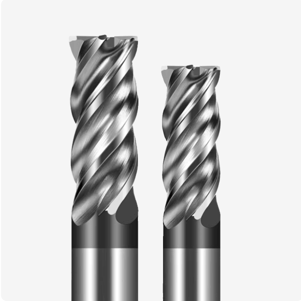
Geometric Structures We Prioritize When Designing Aluminum CNC End Mills
Through extensive experience in high-volume aluminum machining, we’ve learned that standard geometries often underperform in high-speed aluminum cutting. To ensure smooth chip evacuation and stable cutting, systematic optimization of helix angles, flute dimensions, and cutting edge sharpness is essential. Many clients using standard CNC end mill bits—even those with advanced coatings—still encounter chip evacuation issues, tool vibration, and surface marring. This underscores the critical importance of geometry.
Optimizing geometry affects not only surface quality but also tool life and efficiency. Aluminum-specific CNC end mills maintain stable performance even if spindle speed or feed rate isn’t at the theoretical optimum. When designing these tools, we perform extensive test cuts and parameter validation—beyond standard HRC55 protocols—to ensure robustness across aluminum alloys and machining depths.
The Impact of Large Helix Angle Design on Chip Evacuation and Cutting Stability
Tools with standard helix angles often suffer chip clogging and chatter during high-speed aluminum machining. We typically design aluminum CNC end mills with larger helix angles, which smooth chip evacuation and equalize cutting forces. In a comparative study machining 7075 aluminum, larger helix angles yielded better surface finishes and reduced tool wear.
Large helix angles also mitigate vibration. During deep-slot or complex contour machining, chatter can cause surface ripples. Optimized aluminum CNC end mills maintain stable performance even during continuous, 8-hour operations—critical for mass production.
How Large Flute Structures Minimize Aluminum Chip Accumulation
We frequently hear client complaints about “birds’ nest” aluminum chips in deep-slot or high-feed operations, which spike cutting forces and cause chatter. Our solution: wider flutes with optimized profiles to evacuate chips smoothly. Long-run batch machining then avoids the abnormal wear caused by chip clogging.
Adjusting flute angles balances chip evacuation with rigidity. Too wide reduces stiffness and invites chatter; too narrow leads to chip accumulation. We select flute geometry based on machining depth, feed rate, and material hardness—a methodology refined through years of on-site testing.
The Role of Sharp Cutting Edge Design in Preventing Chip Adhesion
Standard steel tools are prone to Built-Up Edge (BUE) in high-speed aluminum machining, creating rough surfaces. Our aluminum-specific CNC end mills feature sharper, thinner cutting edges to minimize adhesion. This is particularly effective on thin-walled components, improving surface finish and reducing rework.
We balance sharpness with structural integrity. Overly sharp edges can chip during roughing or deep slots. Years of client experience allow us to fine-tune edge angles for efficient chip evacuation, reduced adhesion, and durability—crucial for high-volume production in Europe and North America.

Why HRC55-Rated Steel-Cutting CNC End Mills Are Unsuitable for Machining Aluminum
Clients often attempt to use HRC55 steel end mills for aluminum. On paper, these tools are hard and strong, but in practice, they often clog, stick, and tear surfaces. Their geometry is optimized for hard steels, not soft, ductile, adhesive aluminum.
Steel tools resist high cutting forces and temperatures, which doesn’t translate to aluminum machining. Excess heat buildup accelerates wear and causes chatter in deep slots. We often recommend switching to aluminum-specific CNC end mills, adjusting helix angles and flute geometry to solve these issues.
Differences in Cutting-Edge Strength Design
HRC55 steel end mills prioritize edge strength and wear resistance, effective for steel but less so for aluminum. Excessive strength produces duller edges, leading to adhesion and surface tearing. Aluminum CNC end mills with moderately reduced edge strength and increased sharpness perform better, evacuating chips efficiently and producing more uniform cutting forces.
Edge geometry must be customized to wall thickness and groove depth. Thin-walled aluminum parts machined with steel tools often vibrate, leaving surface ripples. Optimized aluminum end mills balance durability and stability for reliable, high-speed performance.
Variations in Flute Count Design
Steel tools typically have more flutes to distribute cutting load, which works for hard materials. In aluminum, more flutes reduce chip evacuation space, causing accumulation. We’ve seen tools clog quickly, requiring frequent shutdowns. Aluminum CNC end mills with 2–3 flutes evacuate chips smoothly while maintaining precision.
Flute count decisions consider depth and material hardness. Fewer flutes suit deep slots and high-volume runs for unobstructed evacuation; more flutes suit light-load, high-speed machining with properly sized channels. This approach balances tool efficiency and operational stability.
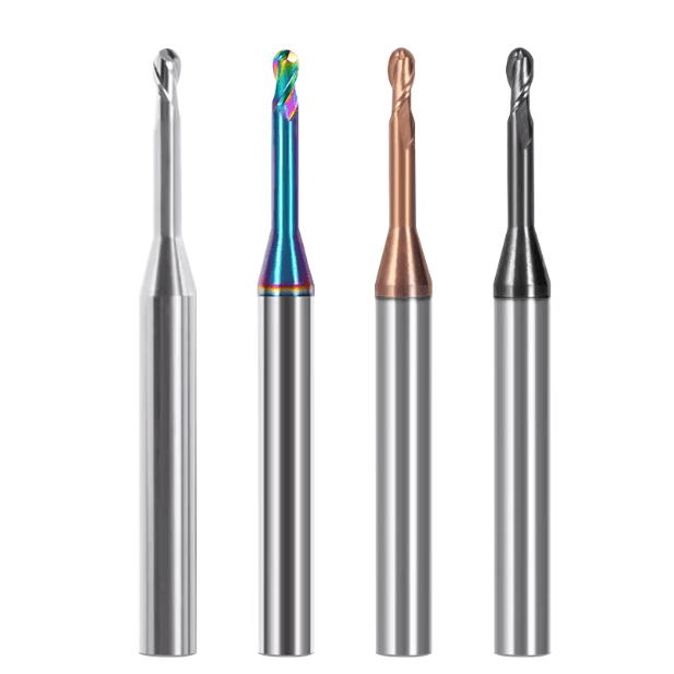
Practical Differences Between Coated and Uncoated Tools
High-friction coated steel end mills often cause aluminum adhesion, increasing cutting forces and reducing surface quality. Uncoated or low-friction tools help chips evacuate and reduce heat buildup.
For long or high-speed runs, uncoated tools may wear faster. Our aluminum CNC end mills enhance edge durability while keeping low-friction characteristics, extending life and preserving surface quality.

Common Structural Variations in Custom Aluminum CNC End Mills for Western Clients
From our experience machining aluminum alloys for clients in Europe and North America, tool structure profoundly impacts machining efficiency and surface quality. During mass production runs, issues such as poor chip evacuation, cutting vibrations, or surface marring frequently arise. These can often be resolved by selecting aluminum CNC end mills with the correct number of flutes and optimized structural design. We do more than follow standard specifications; we consider cutting depth, material type, and spindle speed to customize the optimal tool structure for each client.
On-site testing consistently reveals significant performance differences among tools with varying flute counts. Choosing the right structure not only improves chip evacuation but also extends tool life and reduces rework rates. Depending on batch size, machining type, and cutting force requirements, we often recommend a combination of 2-flute, 3-flute, and roughing tools to meet the demands of high-speed aluminum cutting in large-scale production.
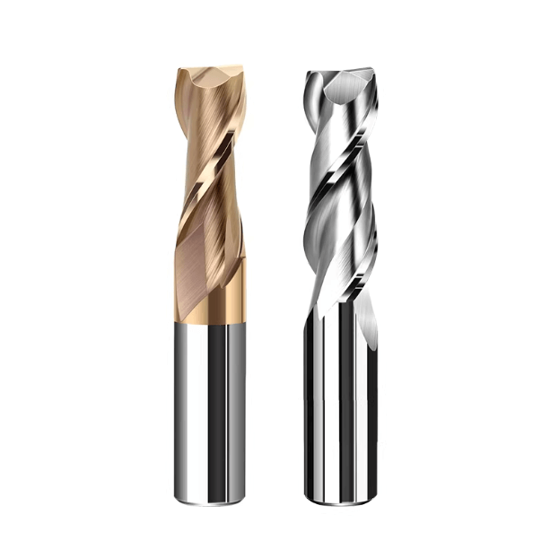
Application Scenarios for 2-Flute Aluminum CNC End Mills
In high-speed aluminum machining, 2-flute CNC end mills are the most frequently chosen, especially for thin-walled parts or long slots. The larger chip evacuation space allows aluminum chips to exit smoothly, minimizing tool clogging and cutting vibrations. Through numerous on-site trials, we’ve verified that 2-flute tools maintain high cutting speeds while delivering superior surface finishes.
For deep-slot or complex contour operations, 2-flute tools generate less heat buildup compared to multi-flute options. Cutting forces are more concentrated with fewer flutes, but by adjusting feed rate and spindle speed, we maintain efficiency without compromising tool durability. If you are machining long slots or thin walls, you can consider a 2-flute geometry and then refine parameters based on material hardness and spindle speed.
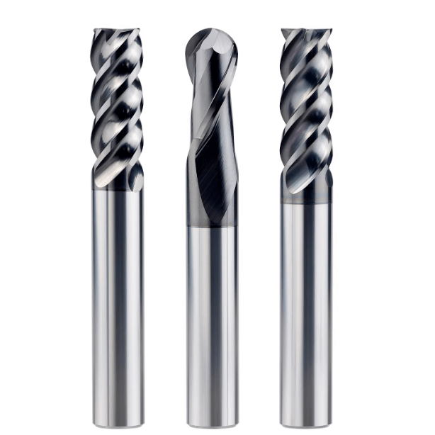
The Balance Between Efficiency and Chip Evacuation with 3-Flute CNC End Mills
Many clients favor 3-flute aluminum CNC end mills to balance cutting efficiency with chip evacuation. Compared to 2-flute tools, 3-flute end mills increase the number of cutting edges, boosting material removal rate—ideal for medium-depth aluminum parts. On-site validation shows that, with optimized helix angles and flute geometry, 3-flute tools maintain a stable surface finish.
We often adjust the tool geometry based on machining depth and aluminum alloy characteristics. If chip evacuation is insufficient, modifying helix angle and cutting edge sharpness ensures smooth aluminum chip flow. If you are handling medium-batch production, you can use 3-flute tools, provided chip evacuation channels are optimized to avoid clogging and tool vibration.
Structural Characteristics of Dedicated Roughing CNC End Mills
For large-volume projects, we recommend dedicated roughing tools to remove material efficiently. Roughing end mills from our china CNC rough end mill factory partner feature robust cutting edges, deep and wide flutes, and evenly distributed cutting forces. On-site testing confirms that these tools enhance material removal while minimizing tool wear and vibration.
However, roughing tools are not suited for finishing. Their coarse cutting edges may compromise surface finish. After roughing, we switch to aluminum-specific finishing end mills to ensure dimensional accuracy and part quality. If you are running large production batches, using a roughing-to-finishing workflow can maximize efficiency and maintain consistent surface quality.

Practical Manufacturing Insights from Our China CNC Rough End Mill Factory Partner
Years of collaboration with our china CNC rough end mill factory partner have shown that every manufacturing stage—from design to final inspection—directly affects aluminum machining outcomes. Flute geometry, cutting-edge polishing, and dynamic balance all determine chip evacuation and surface quality. We’ve participated in on-site cutting trials and parameter validation tests to ensure CNC end mill bits meet rigorous standards for European and North American clients.
Even minor deviations during manufacturing can amplify problems in high-speed aluminum operations. Inadequate flute precision or insufficient edge polishing can lead to chip accumulation and tool vibration. Therefore, we prioritize meticulous geometric optimization tailored to cutting depth, material hardness, and spindle speed, rather than relying solely on material or coating.
The Impact of Flute Machining on Aluminum Processing Performance
Flute machining precision is critical. Improper flute width, depth, or helical angle leads to chip accumulation, poor evacuation, and cutting vibrations. In one 7075 aluminum mass production project, optimizing flute geometry on-site resulted in smooth chip evacuation and reduced tool wear.
Even with the correct base material and number of flutes, small deviations in flute machining can cause localized clogging at high speeds. Integrating flute design with helix angle and cutting-edge geometry ensures consistent performance across production batches. If you are designing tools for large-scale aluminum production, consider flute geometry as a primary factor for both efficiency and tool life.
The Importance of Cutting-Edge Polishing in Aluminum Processing
Cutting-edge polishing minimizes chip adhesion and prevents BUE, while preserving surface finish. On-site comparisons show polished tools reduce surface roughness by 20–30% and extend tool life.
Excessive polishing, however, can create overly sharp edges prone to chipping. We calibrate polishing based on production volume, part thickness, and cutting speed to strike the optimal balance between adhesion prevention and durability. For high-speed aluminum machining, you can prioritize a polished edge while monitoring tool integrity during roughing or deep slots.
The Importance of Tool Dynamic Balancing in High-Speed Aluminum Machining
High-speed spindles in Europe and North America require dynamically balanced tools. Unbalanced tools cause vibrations, chatter, and surface ripples at high spindle speeds. Our aluminum CNC end mills undergo rigorous dynamic balancing inspections and fine-tuning, which, together with optimized cutting-edge geometry, ensure stable, high-quality machining even during continuous high-speed operations.
If you are working with high-precision or thin-walled aluminum parts, dynamic balance should be a key selection criterion. Properly balanced tools extend life, reduce vibration, and improve surface quality—critical in mass production.
Our Recommendations for Selecting Aluminum CNC End Mills
Tool geometry—number of flutes, helix angle, and chip evacuation design—has a greater influence on performance than material or coating alone. Varying alloys, cutting depths, spindle speeds, and batch sizes all require different optimal geometries. We recommend evaluating material properties, machining parameters, and part geometry first, then consider chip evacuation efficiency, cutting forces, and tool durability.
Clients often attempt to use general-purpose HRC55 steel end mills or standard CNC end mill bits for high-speed aluminum. This leads to chip clogging, tool adhesion, and accelerated wear. By comparing tools with different flute counts and geometries, we identify solutions that balance efficiency with tool longevity. If you are currently designing your aluminum machining process, you can start by evaluating cutting depth, spindle speed, and alloy hardness, then reference our proven geometry optimization methods.
Differences in Tool Geometry for Various Aluminum Materials
6061 aluminum is relatively soft with low adhesion, benefiting from slightly sharper edges, large helix angles, and wide chip flutes for high-speed cutting. 7075 is harder, generating greater cutting forces and heat, so we prioritize edge strength while maintaining large flutes to prevent clogging.
If you are machining multiple aluminum alloys, you can adjust cutting edge geometry and helix angle based on material hardness and expected forces. For thin walls or complex contours, sharper edges with large helix angles improve chip evacuation and surface finish. For thick sections or high-strength alloys, balance edge durability and machining stability. You are welcome to share your part drawings or materials for tailored advice.
Tool Selection for High-Speed vs. Standard Machining
High-speed machining demands sharper edges, large helix angles, and optimized chip flutes. Standard-speed operations allow slightly more latitude but still require a balance between durability and chip evacuation. For high-speed applications, aluminum-specific CNC end mills with optimized geometry are recommended. For standard operations, increasing flute count can enhance material removal rate.
You can apply our experience from previous production projects by assessing part size, depth, and aluminum hardness to choose the most suitable tool. Sharing your machining conditions or material drawings allows us to provide precise recommendations.
How to Balance Tool Life and Efficiency in Batch Production
Tools with excessively sharp edges maximize cutting efficiency but accelerate wear. Too thick edges improve durability but reduce efficiency. For batch production, trade-offs should consider alloy hardness, part geometry, and spindle speed to maintain both surface quality and tool life.
Conduct small-batch trials to verify chip evacuation, cutting stability, and wear patterns before finalizing geometry and feed parameters. This approach balances efficiency and tool life, and we encourage peers to use the same judgment based on their specific conditions. Sharing operating conditions or material drawings ensures precise and actionable optimization.