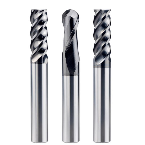
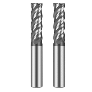
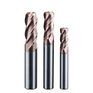
In our project experience over the past decade, breakage of end mill solid carbide has consistently been one of the most common problems our clients face. Whether using solid carbide end mill cutters for side milling high-hardness mold steel or solid carbide roughing end mills for deep roughing cuts, we frequently observe sudden chipping at the tool tip and mid-edge. This is particularly true when using 4-flute solid carbide end mills for deep grooving, where poor chip evacuation or mismatch between cutting parameters and machine rigidity can significantly shorten tool life.
Our field experience indicates that the main factors behind breakage are straightforward: excessive feed rates, incorrect radial-to-axial depth of cut ratios, clamping system runout, excessive tool overhang, inappropriate cooling, and even minor operational errors during the first cut can trigger edge chipping. Tools from different solid carbide end mill manufacturers also vary in particle matrix stability, edge grinding quality, and coating adhesion, all of which directly affect durability under on-site conditions.
We often see clients mistakenly blaming the tool quality when the root cause is actually machining parameters, program settings, or machine rigidity. Tool breakage is never random; there are always patterns and clear signals. When you encounter frequent breakage, can you identify whether the issue stems from the tool, the cutting parameters, or machine conditions?
Common End Mill Solid Carbide Fracture Locations and Causes in the Field
During our on-site tracking of European and American mold factories and mechanical parts clients, we observe tool breakage almost daily. By analyzing fracture locations, we classify breakage into three types: tip breakage, mid-edge chipping, and shank breakage. Understanding these categories allows engineers to quickly determine whether the root cause lies in machining parameters, the clamping system, or the tool itself.
We compile these observations into inspection checklists. Whenever a client reports early tool breakage, we examine fracture morphology and then correlate it with depth of cut, feed rate, machine rigidity, and cooling methods. Our experience confirms that most breakages are caused by operational conditions rather than inherent tool quality. Mastering this assessment logic enables adjustment of machining strategy to prevent repeat incidents.
Tool Tip Breakage – Cutting Method and Instantaneous Load
Tip breakage typically occurs during initial deep groove cuts or ramp feeds. Our field observation shows that sudden increases in depth of cut or excessive radial depth can cause the instantaneous load to exceed the tool tip’s tolerance. This is particularly evident in 304 stainless steel deep grooves. We perform slow trial cuts to assess tool tip load, observing for slight vibration or stringy chips, which indicate cutting force beyond safe limits.
Tip breakage is often accompanied by micro-vibrations of the spindle or abrupt cutting force changes. If microcracks appear on a new tool, we recommend checking the entry path and feed rate for the material. In our experience, gradual ramping and proper entry paths extend tip life more effectively than simply increasing feed rates.
Chipping in the Cutting Edge – Microcrack Propagation Due to Poor Chip Evacuation
Mid-edge chipping usually happens during continuous side milling or deep grooving. Chip recutting, tool sticking, and poor evacuation concentrate stress, forming microcracks that propagate along the edge. For example, during roughing with solid carbide roughing end mills in mold steel, deep cuts combined with insufficient chip clearance often result in noticeable edge chipping.
On-site, we observe chip shape and evacuation paths, and then correlate with machine rigidity and tool overhang. Mid-edge chipping is typically cumulative, not sudden. Adjusting feed rates, improving chip evacuation, and fine-tuning helix angles can significantly reduce breakage frequency.
Shank Breakage – Caused by Clamping System Instability
Shank breakage is closely related to overhang, clamping stability, and spindle condition. Even with appropriate cutting parameters, excessive overhang in ER chucks can induce lateral forces that propagate microcracks along the shank. We measure chuck runout and vibration to verify this effect.
Differences in toolholder design between solid carbide end mill manufacturers also influence overhang capacity. In practice, we often recommend heat-shrink toolholders or reinforced clamping for long overhangs, rather than replacing the tool immediately. This approach maintains machining efficiency while reducing breakage risk.
Typical Cases of Tool Breakage Due to Incorrect Parameter Selection in Solid Carbide End Mill Cutters
In our long-term work with European and American machining clients, tool breakage is often not caused by the tool itself. Instead, it usually results from instantaneous stress concentration due to mismatched cutting parameters. When the depth of cut, feed rate, or the ratio of radial to axial cutting depth is not properly balanced, microcracks can accumulate during machining, eventually leading to edge chipping or tool failure.
To address this, we conduct on-site verification of parameters, taking into account machine rigidity, tool overhang, and material hardness. Our goal is to ensure the cutting load remains within the tool’s capacity. When clients use solid carbide roughing end mills for deep roughing cuts, they often push feed rate and depth of cut to near machine limits. While this improves short-term efficiency, it greatly increases the instantaneous load on the cutting edge.
Excessive Feed Rate and Instantaneous Edge Chipping
We frequently see clients reporting tool breakage shortly after replacement. Careful analysis shows that in most cases, excessive feed rate causes instantaneous loads that exceed the tool’s capacity. We confirm this by observing chip shape, tool vibration, and machine current fluctuations. Importantly, this type of breakage usually results from a single load peak, not gradual wear.
Based on our experience, especially in deep grooving or continuous side milling, solid carbide end mill cutters are prone to tip and mid-edge chipping if feed rate and cutting load are not carefully controlled. We recommend reducing the feed rate or using segmented feeds. Observing chip color and morphology provides a reliable check on load stability, which is often more effective than relying solely on nominal tool parameters.
Excessive Spindle Speed Triggers Microcrack Propagation
In high-speed steel machining, even with normal feed and depth of cut, excessively high spindle speeds can accelerate microcrack propagation along the cutting edge. Field observation shows that delayed chip evacuation at high speeds increases frictional heat, raising localized temperatures and promoting crack growth.
We usually advise clients to monitor chip length and color and check for tool vibration. Some materials are prone to localized overheating at high speeds. Reducing speed while slightly increasing feed can often extend the life of solid carbide roughing end mills. This method has been repeatedly verified on-site and is based on observed machining feedback rather than theory alone.
Incorrect Radial-to-Axial Depth of Cut Ratio
On-site, we observe that many breakages are caused by excessive radial depth or an improper radial-to-axial cut ratio, rather than tool quality. In machining mold steel or high-hardness steel, a large radial cut can produce instantaneous load peaks in the mid-section or tip, triggering microcracks.
Through practice, we advise clients to adjust radial and axial depths based on tool diameter, machine rigidity, and material hardness. By slightly increasing axial depth while reducing radial depth, and combining with proper cutting fluid and chip evacuation, tool life improves significantly. Trial cuts on-site ensure parameter adjustments match the workpiece and machine conditions rather than relying solely on theoretical values.
Fracture Characteristics of Solid Carbide End Mills under Different Machining Materials
Material type has a major impact on tool fracture patterns. Even with identical cutting parameters, 304 stainless steel, mold steel, and aluminum alloys behave very differently due to variations in hardness, cutting temperature, chip viscosity, and chip evacuation. Understanding these differences helps us select appropriate parameters and tool types, reducing edge chipping and sudden tool breakage.
On-site, we often compare tool wear and breakage locations across materials. Observing edge wear patterns, chip morphology, and residual heat allows us to determine whether breakage is caused by thermal stress, operational factors, or machine rigidity. Adjusting feed, depth of cut, and cooling, along with choosing the right tool type—such as solid carbide roughing end mills or 4-flute solid carbide end mills—can significantly reduce breakage risk.
Stainless Steel – Built-up Edge Leading to Edge Chipping
Edge chipping is most common in deep-hole machining of 304 and 316 stainless steel. When cutting speed is excessive or chip evacuation is insufficient, a built-up edge forms, causing sudden local force spikes that propagate microcracks along the edge.
We advise clients to start with a small depth and low feed when machining deep holes or high-hardness stainless steel. Observing chip behavior helps decide whether adjusting parameters is more effective than replacing the tool. This approach has proven to extend tool life while avoiding unnecessary interruptions.
Mold Steel – Heat Concentration Induces Microcracks
In mold steel, heat concentration is a primary cause of gradual microcrack propagation along the cutting edge. In H13 or S136 machining, high continuous loads often result in localized overheating. Microcracks typically start mid-edge and propagate toward the tip along the helix.
Segmented machining, reducing depth of cut, increasing axial feed, and proper cooling are recommended to disperse heat. While not eliminating risk entirely, these adjustments substantially reduce edge chipping or tool breakage in most cases.
Aluminum Parts – Even Light Cutting Can Cause Instant Tool Breakage
Even though aluminum alloys are soft, instantaneous breakage can occur during high-speed machining. Thin walls or light cuts amplify tool vibration, and chip entanglement can propagate microcracks quickly, causing tip or mid-edge failure.
We recommend optimizing chip evacuation paths, controlling tool speed and feed, and considering a 4-flute solid carbide end mill with a helix or wavy edge to improve cutting stability. While not guaranteeing zero breakage, these measures significantly reduce risk and enhance tool life and machining stability.
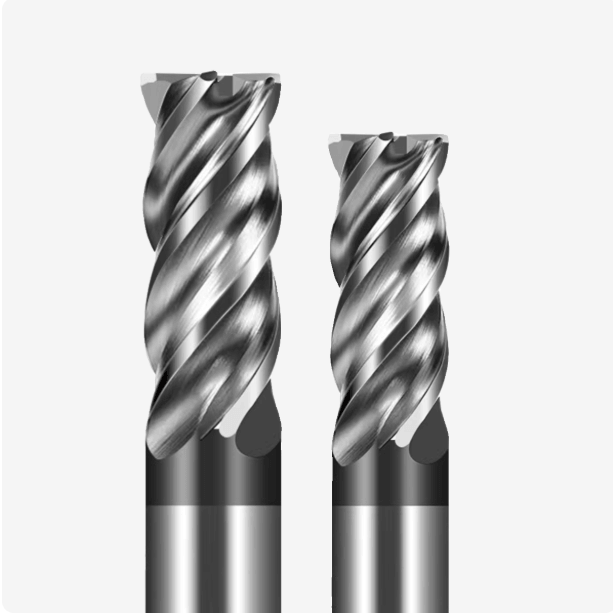
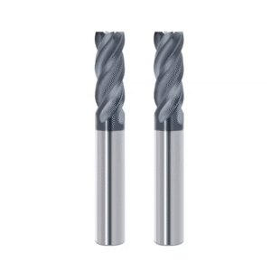
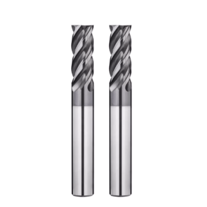
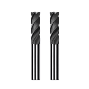
Common Problems of Tool Breakage in 4-Flute Solid Carbide End Mills
In our years of field observation, 4-flute solid carbide end mills perform stably in shallow side milling. However, tool breakage becomes significant in deep grooving or long-stroke operations. We have found that insufficient chip evacuation and chip accumulation are the main contributors to cutting edge failure. In practice, chip backflow or groove blockage can suddenly increase cutting force, causing microcracks to propagate at the tool tip or mid-edge, often resulting in abrupt tool breakage. To evaluate this, we first examine chip condition and machine vibration on-site.
We also observed that tool breakage is closely related to tool diameter and machining depth. Small-diameter 4-flute end mills in deep grooves or continuous cuts experience slightly longer overhangs, and machine rigidity is often reduced, amplifying vibration. Microcracks at the tool tip can propagate rapidly under repeated load cycles. Based on field experience, we advise customers to check chip evacuation and cutting stability first, rather than immediately replacing the tool. This approach effectively reduces tool breakage rates.
Insufficient Chip Evacuation Space in Deep Grooving
In our customer work, insufficient chip evacuation space is the most common issue for 4-flute tools in deep grooves. When the depth of cut is large, the tool diameter is small, or the helix angle is unsuitable, chips tend to flow back and clog the groove. This causes a sudden spike in tool load. We evaluate chip evacuation by observing chip morphology and cutting noise. Significant chip back-cutting or tip scraping indicates that cutting parameters need adjustment or chip path improvement.
Optimizing chip evacuation is not limited to reducing depth of cut or feed rate. Adjusting the helix angle or selecting a wave-edge design can also improve chip flow, reducing stress on the mid-section and tip. These methods, validated in field operations, help extend tool life and reduce breakage in deep groove machining.
Secondary Chip Cutting Leads to Rapid Edge Breakage
In high-efficiency machining with small-diameter 4-flute tools, chips often fail to evacuate promptly and may be recut by the cutting edge. This accelerates microcrack propagation, leading to tip or mid-edge breakage. Customer case studies show that continuous machining of thin-walled mold steel or stainless steel is particularly susceptible to this issue. We monitor chip length and morphology and assess edge load through vibration analysis.
To mitigate this, we recommend increasing axial feed, reducing the radial cutting ratio, applying high-pressure coolant, and optimizing the tool helix angle. These field-proven strategies significantly reduce tool breakage in small-diameter deep-groove operations while maintaining productivity.
Hidden Risk of Vibration in Small-Diameter 4-Flute Cutters
During on-site monitoring, vibration in small-diameter 4-flute cutters is often overlooked but significantly affects microcrack propagation at the tool tip. Even with appropriate depth and feed, insufficient machine rigidity or clamping runout can amplify high-frequency vibrations, causing sudden breakage. We determine vibration severity through on-site measurement and overhang analysis.
Mitigating vibration relies on proper machining parameter matching, tool rigidity, and clamping selection. For deep grooves with high overhang, heat-shrink tool holders or short-overhang solutions, combined with optimized feed and cutting speeds, have been repeatedly verified to reduce breakage. However, this must be judged based on specific workpiece and machine conditions.

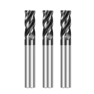
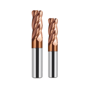
The Real Cause of Solid Carbide Roughing End Mills Breakage in Roughing
In our long-term experience tracking customer sites, tool breakage during roughing is rarely caused solely by tool quality. In scenarios with large depths of cut and high feed rates, cutting and impact forces often exceed expectations. By observing chip morphology, vibration, and tool wear, we have determined that fractures primarily originate from cutting impact, machine tool rigidity, and accumulated thermal cycling, rather than simple edge brittleness. Understanding these factors helps us quickly pinpoint the root cause on-site and guide customers to adjust machining strategies effectively.
We also observed that many customers attribute breakage to the solid carbide itself. However, field practice shows that adjusting cutting parameters and improving clamping and cooling methods can often reduce breakage significantly. Based on on-site data and customer feedback, we categorize roughing tool breakage into three main factors: impact from the wavy edge structure, insufficient machine rigidity, and micro-fatigue crack propagation due to thermal cycling.
Wavy Edge Structure is Susceptible to Impact
In our field experience with wavy edge roughing end mills, intermittent cutting or scrap entry frequently damages the cutting edge. Particularly during roughing of die steel or high-hardness steel, the impact force from scrap can exceed the edge’s bearing capacity, initiating microcracks that propagate along the cutting edge. We typically assess potential damage by observing chip morphology, cutting noise, and machine current fluctuations.
If you are using wavy edge roughing end mills, we recommend starting with shallow depths of cut and low feed rates to monitor tool load. Gradually increasing these parameters, while observing chip behavior, helps match cutting parameters to the wavy edge design, reducing impact damage and extending tool life. Controlling residual material entry and ensuring smooth chip removal are also critical to preventing edge chipping.
Insufficient Machine Rigidity is More Common Than Tool Issues
Through on-site monitoring, we found that tool breakage in deep-cut roughing is often more linked to machine rigidity than tool material. Even high-quality solid carbide roughing end mills can develop microcracks in the mid-edge or shank if the machine experiences runout under large overhangs or heavy loads. We determine whether breakage stems from machine rigidity by measuring clamping runout, tool vibration frequency, and overhang length.
Experience shows that optimizing machine support and clamping is more effective than replacing the tool. For deep grooves or large mold blanks, reducing overhang, increasing clamping rigidity, and distributing cutting loads properly significantly reduces breakage. We advise customers to combine these adjustments rather than relying solely on tool strength.
Thermal Cycling Leads to Micro-Fatigue Fracture
During long continuous roughing operations, we frequently observe tool breakage caused by accumulated micro-fatigue. Cutting force and tool surface temperature fluctuate over time, generating microcracks within the edge. These cracks expand with each cutting cycle, eventually causing breakage. We assess thermal cycling effects by observing chip color changes, tool wear distribution, and vibration patterns.
Practical experience indicates that reducing peak cutting temperatures and optimizing cooling and chip removal can significantly slow micro-fatigue crack propagation. On-site, we often use segmented machining, adjust feed rate and depth of cut, and implement rotation and thermal management strategies. While not absolute rules, these methods consistently extend roughing end mill life, validated across numerous long-term projects.
Clamping System Issues as Hidden Causes of Tool Breakage
Long-term on-site monitoring reveals that many tool breakage incidents are not due to the tool itself but are often caused by clamping system problems. Even with proper cutting parameters and tool selection, insufficient chuck runout control or tool holder rigidity can allow microcracks to propagate at the tip and along the edge. This risk is especially pronounced in deep grooving, small-diameter tools, or operations with large overhangs. Understanding clamping impact helps determine the root cause of breakage on-site rather than relying solely on tool strength.
We have also observed wide variations in clamping system maintenance and usage among customers. Even high-precision machines can experience tool vibration due to chuck wear or improper installation. We recommend measuring chuck runout regularly, monitoring tool vibration, and checking chip evacuation to assess clamping impact comprehensively. This practical approach reduces the risk of tool breakage caused by clamping issues.
Runout Exceeding 0.01mm Causes Edge Load Imbalance
Our experience shows that when chuck or tool holder runout exceeds 0.01mm, cutting edge load becomes unbalanced. Even with appropriate depth and feed, this small deviation can quickly propagate microcracks, leading to tool breakage. We typically evaluate this by measuring runout, observing vibration, and monitoring machine current.
If you notice abnormal tool life, we advise checking the clamping system first rather than replacing the tool immediately. Adjusting chuck installation, ensuring cleanliness, and proper tool holder positioning can significantly reduce breakage risk. This method is actionable and practical rather than relying solely on the tool’s nominal specifications.
Heat Shrink Tool Holders vs. ER Chucks – Performance Differences
In our practice, heat shrink tool holders outperform ER chucks in deep grooves or large overhang machining. Heat shrink holders provide higher radial stiffness, reducing tool tip vibration and the likelihood of microcrack propagation. ER chucks, being less stiff, allow slight vibrations to accumulate at the tip, accelerating breakage.
In actual operations, we select clamping solutions based on tool diameter, overhang, and workpiece material. Not all tools are suitable for long overhangs; choosing the right holder, combined with optimized cutting parameters, reduces breakage while maintaining efficiency. Recommendations are based on field data and repeated verification, not absolute theory.
Vibration Amplification from Increased Overhang
We have observed that small-diameter tools with excessive overhang amplify vibration, transmitting it to the tip and promoting microcrack propagation. Even with appropriate depth and feed, long overhangs can create uneven load and higher breakage probability. We assess vibration effects by measuring overhang, observing chip morphology, and monitoring machine vibration.
For deep grooving or thin-wall machining, shortening overhang or using high-rigidity holders, combined with proper cutting parameters, effectively reduces vibration-induced breakage. We advise on-site test cuts to verify chip and vibration conditions before adjusting overhang or clamping. This balances efficiency with reduced tool wear, based on long-term field experience.
Improper Cooling Accelerates Solid Carbide End Mill Cutter Damage
Field monitoring of customer machining operations shows that cooling methods directly influence tool life and fracture behavior. Even with appropriate cutting parameters, intermittent or insufficient coolant flow can accelerate microcrack propagation along the cutting edge. This effect is most pronounced in deep groove and cavity machining, where inadequate heat dissipation leads to localized overheating, reducing the tool’s load-bearing capacity. Observing chip color and tool wear allows quick assessment of cooling adequacy.
Cooling requirements vary by material and machining method. For high-hardness steels or titanium alloys, rapid localized heat accumulation can propagate microcracks even with intermittent cooling. Continuous or high-pressure cooling not only lowers edge temperature but also improves chip evacuation, extending solid carbide end mill cutter life. We advise selecting a cooling strategy based on machine tool conditions, not solely on the tool’s heat resistance.
Intermittent Cooling May Lead to Microcrack Propagation
On-site, several mold and machine parts manufacturers have experienced microcrack propagation along the helical cutting edge under intermittent cooling. Continuous deep-groove cutting in high-hardness steel or stainless steel causes periodic temperature spikes at the cutting edge. These thermal cycles accelerate microcrack growth, eventually leading to breakage. We assess the risk by monitoring chip morphology and tool vibration.
For deep grooves or high-load roughing, intermittent cooling often fails to remove heat timely. Continuous or high-pressure cooling helps maintain stable cutting-zone temperature while reducing microcrack accumulation. Observing tool wear and chip conditions during trials is more reliable than assuming the tool material alone can withstand thermal stress.
Practical Effects of High-Pressure Cooling in Deep Cavity Machining
High-pressure cooling significantly improves chip evacuation and reduces peak edge load during deep cavity machining. Stable coolant flow removes localized heat and helps clear chips, lowering the risk of edge chipping and tool breakage. Field verification shows that even in deep-cut roughing, appropriate high-pressure cooling extends the lifespan of solid carbide roughing end mills.
For optimal results, pay attention to nozzle position and flow direction to ensure direct cooling of the cutting edge and chip channel. Experience indicates that high-pressure cooling combined with optimized feed and depth of cut often protects the tool better than reducing feed or depth alone.
Materials Prone to Thermal Chipping under Air Cooling
Thermal chipping is severe when machining heat-sensitive materials such as high-hardness steels and titanium alloys using air or low-flow cooling. Even with proper feed and depth, inadequate heat removal causes rapid tool-edge temperature rise, accelerating microcrack propagation and eventual tool breakage. Chip morphology, edge wear, and machine vibration help assess thermal chipping risk.
For heat-sensitive materials, air cooling alone is insufficient. Field operations usually combine optimized cutting parameters, reduced overhang, high-pressure or continuous cooling, and tool temperature monitoring to lower thermal chipping. This approach is based on extensive on-site experience and significantly improves solid carbide end mill durability.
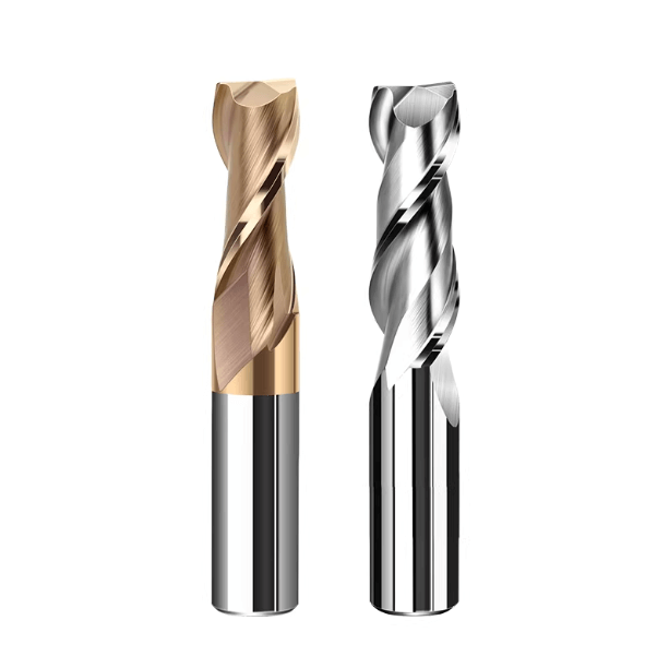
Why Cutting Tools from Different Solid Carbide End Mill Manufacturers Perform Differently
Our long-term experience with European and American machining clients shows that even under identical cutting conditions, cutting tools from different manufacturers can perform very differently. This variation is primarily due to matrix particle stability, edge treatment processes, and coating adhesion stability, which directly affect crack resistance and tool edge life. On-site observations of chip morphology, tool wear, and breakage location help us quickly identify the source of performance differences, rather than relying solely on tool diameter or material hardness.
Even within the same batch, machining consistency can differ significantly between manufacturers. On-site test cuts and vibration monitoring reveal that some tools develop micro-chipping faster during continuous machining of high-hardness steel or deep grooves, while others remain more stable under the same conditions. Choosing the right end mill manufacturer and tooling process is therefore critical for machining stability and extending tool life.
Matrix Particle Stability Strongly Influences Crack Resistance
In field machining, we observed that the more stable the tool’s matrix particles, the better it resists microcrack propagation under high loads and deep-groove operations. For example, in rough machining of mold steel, tools with uniform particle distribution and high sintering quality show less mid-section crack propagation, even under instantaneous cutting impacts. Cross-section inspections and cutting load analysis confirm that matrix particle stability is a key factor in crack resistance.
Tool fracture is rarely caused by a single factor. Repeated cutting impacts and thermal cycles cumulatively fatigue the matrix particles. Selecting tools with high particle stability significantly improves the service life of solid carbide roughing end mills and 4-flute end mills under high-load conditions. Field experience shows this selection is often more effective than solely optimizing cutting parameters.
Edge Treatment Determines Micro-Chipping Initiation
Field tracking of tools from different manufacturers shows that micro-chipping often starts at poorly treated edges. Tools with fine polishing and chamfering delay crack initiation and reduce micro-chipping propagation during deep-groove machining of high-hardness steel or stainless steel. Tools with uneven edge sharpness are prone to micro-cracks at the tip or mid-section, increasing breakage risk.
We advise customers to prioritize edge machining processes and tip chamfering quality when selecting tools. Even with identical machining parameters, finely finished edges provide more reliable performance during continuous machining of high-hardness materials, reducing production interruptions.
Coating Adhesion Stability Impacts Continuous Machining
Coating adhesion stability strongly affects tool performance during high-load continuous machining. Tools with uneven or weak coatings are more likely to experience localized friction, edge overheating, and microcrack propagation, leading to premature breakage. We assess coating adhesion and its impact on tool life by observing chip formation and surface wear.
Tools with uniform coatings and appropriate thickness maintain cutting stability and lower tip wear, even during long-duration, high-load machining of stainless steel, high-hardness steel, or deep grooves. This assessment is based on extensive field practice and customer feedback.
Recurring Tool Breakage Often Stems from Program Details
On-site, we often find that tool breakage—whether tip breakage, mid-edge chipping, clamping system vibration, or cooling-related crack propagation—is triggered repeatedly by the same toolpath details. After confirming no abnormalities in tool specifications, spindle status, or clamping methods, subtle movements in the program often cause localized impact. Many breakages occur at cut end, corner transitions, or when re-contacting residual material, rather than during continuous cutting.
We advise reviewing tool breakage by rerunning the program and observing tool load changes during entry, exit, turning, and subsequent machining moves. For deep grooves, narrow cavities, or high-hardness materials, focus on sudden spikes in the tool load curve. Often, premature solid carbide end-mill failure is due to localized load spikes rather than incorrect overall parameters.
Secondary Collision During Retraction
Many cases show stable main cuts, but during retraction, insufficient tool lift or a small lateral exit angle causes the cutting edge to contact already-machined sidewalls, resulting in micro-chipping. This is especially common with small-diameter 4-flute tools or deep grooves. Micro-cracks can propagate in unseen areas if retraction causes secondary contact.
For long grooves or continuous contours, verify clean tool retraction, checking for any scraping between the Z-axis lift and lateral departure. On-site, slowing down single-segment toolpaths often prevents last-millimeter breakage. Specific toolpaths or machining diagrams can help pinpoint these issues, which are rarely identifiable from a single broken tool photo.
Insufficient Corner Deceleration Causes Localized Impact
Cutting edge life often drops when entering corners, even if straight-line machining is fine. On-site tests show insufficient deceleration at corners causes localized spikes in radial cutting load. Particularly in mold steel or stainless steel, these sudden spikes can break previously stable cutting edges if heat and stress are not released in time.
Verify corner radius and feed decay settings. Adding a buffer zone at corners often improves tool life more effectively than reducing overall parameters. Monitor spindle load curves to detect abrupt spikes, as consecutive breakages frequently originate here.
Residual Material Entry Causes Instantaneous Load Doubling
During roughing-to-finishing transitions or multi-area machining, tools can encounter incompletely removed residual material. This sudden change in cutting thickness significantly increases impact on the first cutting edge, causing apparent sudden breakage even if fatigue has already accumulated.
For layered machining, corner clearing, or repeated passes, ensure stable allowances between layers. Even a 0.2mm residue can spike tool-tip load at high spindle speeds. Analyzing material grades, allowance settings, and on-site chip conditions together clarifies these issues.