In a CNC workshop, the most dreaded sound isn’t the roar of the spindle—it’s that sharp, piercing shriek. The moment you hear high-frequency vibration (chatter), you know your expensive long end mill is on borrowed time.
We recently assisted a German Tier 1 automotive supplier with a recurring nightmare: finishing deep corners in HRC 58–62 hot-work tool steel. They were using long reach end mills with extreme overhangs to reach the bottom of the mold. The results were predictable: poor surface finish and frequent edge chipping. Even with “premium” brands, their yield rates were a total gamble.
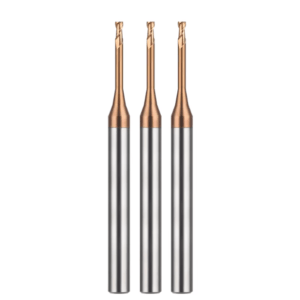
As a China long end mills manufacturer with over 15 years in the trenches, we know that once your length-to-diameter ratio exceeds 5:1—or 8:1—the rules of machining change. You cannot rely on brute force. You have to balance rigidity and cutting forces like a tightrope walker.
This is especially true for an HRC65 long neck end mill. Many peers fall into the trap of thinking higher RPMs or drastically lower feeds are the only solutions. In our experience, if you don’t manage the relationship between cutting resistance and chip evacuation, a long neck end mill for hardened steel will fail. Excessive friction leads to built-up edges (BUE), and the tool is ruined instantly.
Here are five “deep-cavity strategies” we’ve validated across hundreds of deliveries to help you escape the vibration quagmire.
Have you ever slashed your feed rate to 20% just to keep a 50mm-deep tool from snapping? Let’s talk about why you might not have to.
Prioritizing Rigidity: Why We Recommend Long Reach End Mills Over Full-Flute Tools
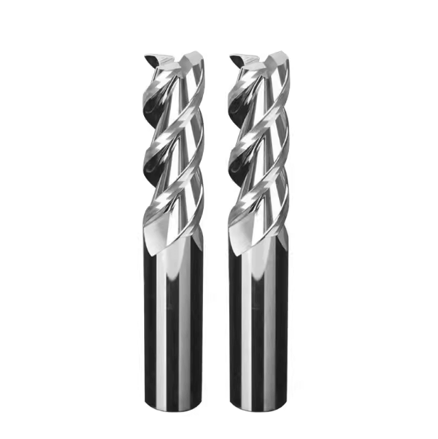
When facing deep cavities, many operators instinctively grab a full-flute end mill. They assume more cutting edge equals more versatility. However, our manufacturing data shows this is often where the disaster begins.
A full-flute tool has a much larger surface area engaged in the cut. This causes the cross-sectional rigidity to decrease exponentially as the flute length increases. Even with a conservative feed, the tool will deflect. This triggers harmonic resonance (chatter) and dimensional inaccuracies.
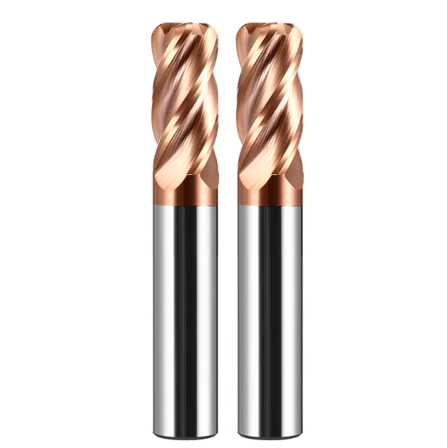
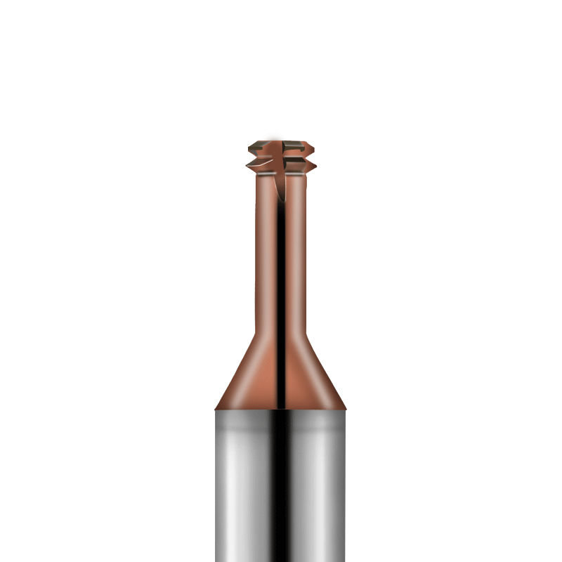
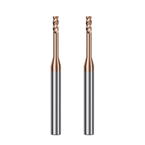
We prefer long reach end mills—tools with a relieved neck. This design shortens the effective cutting edge and reinforces the neck diameter. It concentrates the cutting force at the tip. When we develop custom solutions for Western clients, we consistently see that a short-flute, long-neck design offers at least 30% more bending resistance than a full-flute tool of the same length. The goal isn’t just to stop the tool from breaking; it’s to keep your side walls perfectly perpendicular.
The Physics of Deflection: Relieved Necks vs. Full-Length Cutting Edges
Deflection is the arch-enemy of deep cavity work. Think of a full-flute tool like a slender leaf spring. Lateral forces are distributed across the entire flute length, creating a ruinous arc-like curvature. This is why you get “barrel-shaped” walls—wider in the middle and narrow at the ends.
A relieved-neck design confines the cutting resistance to a short segment at the tip. The rest of the tool acts as a rigid support shaft that absorbs tensile and compressive loads. This structure suppresses radial deflection.
In our lab tests, the tip displacement of a long end mill with a relieved neck is significantly lower than a full-flute version. This allows you to run higher surface speeds without the tool “shattering.” For a China long end mills manufacturer, optimizing that neck taper and the transition radius (R-angle) is the secret to high-stability finishing in hardened steel.
Calculating the Optimal “Effective Length” for High-Precision Molds
We often see engineers leave too much safety margin. They might pick a tool with a 50mm effective length (L1) for a 40mm deep cavity. In our view, every extra millimeter of overhang is a waste of rigidity.
When using a long neck end mill for hardened steel on HRC65 material, our rule is: “Just enough is perfect.” Ideally, the effective length should only exceed the machining depth by one or two pitch lengths. This provides just enough clearance for chip evacuation and prevents shank interference.
When calculating this, you must account for the relief angle and the gage length of the tool holder. We always advise clients to use CAM simulation to check the tool holder-to-workpiece clearance. Rigidity is a calculated value, not a “feeling.” Cutting that extra 5mm of redundant overhang is often the difference between a screaming tool and a silent, “butter-like” cut.
When you look at your setup, have you calculated exactly how much feed rate you’re sacrificing to unnecessary overhang?
The Ultimate Tool for High-Hardness Steel: Parameter Tuning for HRC65 Long Neck End Mills
When machining materials over HRC 60, the process is no longer simple “cutting.” It is more like high-pressure material fracturing. In our experience—especially when using HRC65 long neck end mills—the biggest challenge isn’t the hardness itself. It is the sudden softening of the cutting edge due to heat.
This environment is both ultra-hard and brittle. It demands extreme substrate toughness and “red hardness” from the tool coating. We have found that with long-overhang setups, if you don’t channel cutting forces into the spindle, the tool shank will resonate. When that happens, even the most expensive carbide tools become as fragile as glass.
We advise against blindly following standard handbook parameters for ultra-hard materials. Instead, we watch the chips. Ideally, chips should be fine, fragmented, and show slight thermal discoloration (turning blue or straw-colored). As a China long end mills manufacturer, our factory tests show that a “small steps, fast pace” approach is best. Reducing the axial depth of cut (Ap) and using high-frequency, reciprocating toolpaths protects your expensive workpieces from the debris of a chipped tool.
Tackling HRC65 Hardened Steel: Why Constant Chip Load Prevents Chipping
In hard milling, sudden load fluctuations are catastrophic. This is a major risk when a long neck end mill for hardened steel enters a corner. As the tool’s engagement angle (arc of contact) spikes, the feed per tooth—or “Chip Load”—spikes with it.
This sudden overload causes the slender neck of the tool to “bounce” or deflect. This is the #1 trigger for tool chipping. We always urge clients to use CAM software to maintain a dynamically constant cutting load. Whether the tool is moving in a straight line or an arc, the resistance on the cutting edge must remain uniform.
We’ve applied this “constant load” logic to high-precision gear molds. By precisely controlling minute variations in the radial depth of cut (Ae), we compensate for the lack of rigidity in long-overhang setups. When cutting forces stay within a predictable range, tool wear stays linear. This allows you to forecast tool changes with pinpoint accuracy. In HRC65 steel, stability is far more valuable than raw speed.
The RPM-Feed “Sweet Spot” for Long-Neck End Mills
Finding the balance between RPM and feed rate is like dancing on a knife’s edge. Many assume higher RPM equals faster results. However, with a long end mill, excessive speeds trigger high-frequency harmonic vibrations. These vibrations destroy micron-level cutting edges instantly.
When tuning for high-hardness components, we favor a specific combination: low RPM, moderate feed, and shallow radial depth. This setup reduces frictional heat and protects the tool’s nano-coating.
One lesson from the field: when the cutting sound shifts from a dull rumble to a sharp, crisp tone, you’ve likely crossed the “sweet spot.” It is wiser to find a parameter set that lets the tool run for four hours without needing radius compensation. For long reach end mills, we recommend limiting surface speed to 80% of catalog values and increasing the frequency of passes. It looks slower, but for “zero-scrap” precision work, it is the most reliable strategy.
Are you really willing to risk a $5,000 mold just to save five minutes of cycle time?
Toolholders and Clamping Systems: The Overlooked Source of Vibration
When vibration ruins a deep-cavity finish, most engineers blame the tool or the RPM. But on our shop floor, we’ve found that 40% of vibration issues start with the clamping system. For a long end mill, the holder is the most critical link in the damping chain.
If the concentricity is poor or the clamping force is uneven, centrifugal forces at high speeds are amplified. No matter how perfect the tool geometry is, a bad holder will leave irreparable chatter marks.
We advise checking the dynamic balance and taper contact ratio before starting any long-reach project. While standard ER collets are versatile, they often lack the lateral rigidity needed for deep-cavity work. As a China long end mills manufacturer, our lab tests show that switching to a high-rigidity holder can reduce machining noise by 5–8 decibels. A better clamping system allows the tool to focus on cutting, not chattering.
Why Even the Best Tools Perform Better in Shrink-Fit Holders
Side-lock (Weldon) holders have a fatal flaw: eccentricity. The side screw forces the tool against one side of the bore. For long reach end mills, this is an absolute nightmare. In tests with our Western clients, we saw that the minute deviations in a side-lock holder are amplified several times at the tool tip.
In contrast, shrink-fit holders use thermal expansion to achieve 360-degree, uniform clamping. This symmetry is critical for dynamic stability. Shrink-fit holders also have a slender profile, which works perfectly with our neck-relief designs for tight spaces. Yes, they require an equipment investment, but they pay for themselves in longer tool life and zero polishing time. If you’re still using side-locks for HRC65 finishing, you are squandering half your tool’s potential.
Eliminating Radial Runout: The “1-Micron Principle”
In our shop, we live by the “1-Micron Principle”: for every extra micron of radial runout, tool life drops by roughly 10%. On a long neck end mill for hardened steel, the edges are incredibly delicate. Uneven runout puts a disproportionate load on a single edge, leading to a chain reaction of chipping.
Because of the extended lever arm on long-neck tools, a tiny error at the spindle becomes a massive oscillation at the tip. This is the root cause of high-pitched chatter.
We mandate that technicians use a dial indicator to measure runout at the furthest point of the Effective Length. If it exceeds 0.005 mm (5 microns), do not proceed with high-speed machining. While checking runout takes time, it ensures you can run your machines unattended through the night shift. This attention to detail is what separates a top-tier mold shop from an average one.
Have you ever noticed how that annoying vibration vanishes the moment you re-seat the tool and fix the runout?
Optimizing Toolpath Strategies: Using Trochoidal Milling to Mitigate Force Fluctuations
When machining complex deep-cavity molds, traditional linear toolpaths are a nightmare for tools with high length-to-diameter ratios. Whenever a long end mill engages in full-width cutting or hits a “dead corner,” cutting forces spike instantly. This leads to deflection—the inevitable result of excessive overhang.
To solve this, we strongly recommend adopting Trochoidal Milling or dynamic milling strategies. By using a continuous series of small circular motions, the cutter maintains a constant angle of engagement. This fundamentally eliminates the force fluctuations that long reach end mills usually encounter.
The principle is simple: use “mechanical fluidity” to overcome material resistance. While assisting a medical device manufacturer with deep-slotting in stainless steel, we used trochoidal paths to break heavy loads into smooth, light cycles. This created ample room for chip evacuation and, more importantly, suppressed the resonance triggered by sudden load changes. As a China long end mills manufacturer serving global markets, we know that even the best tool is useless if paired with a poor toolpath. It’s like driving a supercar through a swamp—you’ll never see its true potential.
Depth-First or Width-First? Fine-Tuning Step-over for Corner Finishing
When “Rest Machining” (clearing residual material) in deep cavities, we’re often asked: is it better to increase axial layers (depth) or reduce lateral step-over? For an HRC65 long neck end mill in hardened steel, we always favor a “Width-First” strategy using an extremely small radial step-over (Ae).
Radial rigidity is the weakest link for any long-neck tool. By minimizing the Ae value, you ensure the tool isn’t “sucked into” the side wall, preserving your profile accuracy.
In one project for automotive lighting molds, we reduced the step-over from 10% of the cutter diameter down to 3%. It looked slower on the CAM simulation, but the actual efficiency soared. Why? Because we eliminated the downtime for tool replacements and inspections. When you adjust that slider in your CAM software, don’t think about “metal removal rates.” Think about whether that micron-scale edge on your long neck end mill for hardened steel can glide smoothly under pressure.
Trading Axial Depth (Ap) for Machining Stability
Many machinists prioritize efficiency by increasing the axial depth of cut (Ap), believing a deeper cut is necessary for a robust chip load. With long-reach tooling, this is a major mistake. Our destructive testing shows that excessive Ap leads to a massive surge in cutting torque. This creates a “lever effect” that twists the tool at its most vulnerable point: the neck.
For maximum stability, we recommend limiting the Ap to 0.05 – 0.1 times the cutter diameter. You then compensate for the shallow depth with a high feed rate. This “shallow and fast” strategy is the gold standard for the unmanned, “lights-out” operations our clients run in North America. Reducing the Ap allows heat to escape through the chips rather than baking into the bottom of the cavity. We’ve found that halving the Ap while increasing the feed rate by 1.5x significantly drops vibration and creates a superior surface finish.
Be honest: have you ever pushed your depth of cut to save a minute, only to spend an hour trying to extract a broken tool head from the bottom of a mold?
Cooling and Chip Evacuation: Preventing Vibration and Recutting in Hardened Steel
In deep-cavity work, operators focus on rigidity but overlook a hidden killer: chip recutting. When a long end mill is deep in a pocket, chips that aren’t cleared immediately get pulled back into the cutting zone. This compaction generates massive instantaneous loads and that high-pitched vibration that sends shivers down an engineer’s spine.
In our experience, most “unexplained” tool failures can be traced back to chip accumulation. For steels exceeding HRC 60, thermal management and evacuation are inseparable. Chips carry away the heat. If those incandescent metal strands stay in the cavity, they drive up the temperature at the tool tip, causing the coating to oxidize and spall.
In deep-cavity work, chip evacuation is a higher priority than cutting speed. If your path is obstructed, even the most expensive tool will suffer structural rigidity collapse due to heat soak.
Air Blast vs Oil Mist: A Case Study in Temperature Management
We once assisted a die-casting mold manufacturer who was using traditional emulsion coolant in a 60mm deep narrow cavity. It was a disaster. The fluid couldn’t establish convection; it just turned into a “boiling bath,” cutting the life of their long neck end mill for hardened steel in half.
We had them switch to high-pressure Air Blast and MQL oil mist. The air forcefully clears the chips, while the MQL creates a molecular-level lubricating film that prevents chips from welding to the tool.
For an HRC65 long neck end mill, we favor this “cold-dry” philosophy. Liquid coolant hitting a hot, brittle carbide tool in a deep pocket causes thermal shock, leading to micro-cracks. Stability in edge temperature is more critical than the lowest temperature. High-pressure air clears the path so that every pass cuts virgin material, not old chips.
Why a China Long End Mills Manufacturer Obsesses Over Flute Geometry
As a China long end mills manufacturer providing custom solutions, we run rigorous simulations to model chip trajectories across different flute shapes. Under long-overhang conditions, torsional rigidity is low. If flutes clog, cutting torque can double instantly.
We tell our export clients: deep-cavity machining isn’t about “brute force miracles”—it’s about controlling the path of every single chip. We optimize the surface finish of our flutes specifically to reduce metal-to-metal friction.
We often see engineers reduce air pressure to keep the machine clean, only to pay the price when their long reach end mills snap. A clean evacuation environment keeps the cutting sound crisp. If you hear a dull, grinding “squeak,” chips are already packing in. For stable, unattended machining, would you rather have a slightly messy machine or a broken tool lodged in your workpiece?