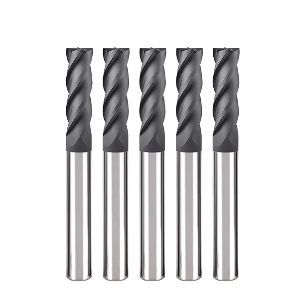
As a team with fifteen years of experience as a carbide end mill manufacturer, the most frustrating issue we handle isn’t standard wear—it’s sudden, unpredicted “edge chipping.”
Just last week, a long-term client was machining 4140 alloy steel (HRC 35). Their end mills for steel, which usually run with rock-solid stability, suddenly suffered severe chipping during the second pass. The client’s first instinct was to blame the carbide substrate quality. However, once we reviewed the G-code and spindle load data, we found a classic disconnect between the process and the tool’s physical limits.
This happens constantly in B2B support. In reality, edge chipping is rarely a manufacturing defect. It is almost always a result of systemic rigidity failure or parameter errors. Whether you use premium custom tools or standard end mill bits for steel, ignoring chip control, thermal shock, or runout will make the hardest carbide as fragile as glass.
This is especially true for roughing end mills. Many machinists fall into the trap of thinking a lower feed rate protects the edge. Actually, the opposite is true: a feed rate that is too low causes friction and rubbing, which accelerates chipping.
We aren’t going to give you textbook definitions. We’re sharing hard-won, real-world experience from our labs and our clients’ shop floors. We will dissect the “invisible killers” of carbide end mills so you can stop them in your own shop.
Have you ever matched every catalog parameter perfectly, only to have the edge “explode” the moment it hits the part?
Insights from the Shop Floor: Typical Characteristics of Chipping in End Mill Bits for Steel
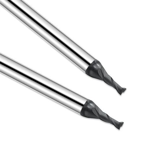
When we troubleshoot a field complaint, our first step is always the same: stop the machine and grab a magnifying glass. When machining grades like 4140 or H13, the damage pattern on end mill bits for steel acts as a “crime scene report.” Unlike wear, chipping isn’t gradual. It usually comes with a sudden change in sound—moving from a crisp hum to a dull thud or a metallic screech. If you see irregular scratches on the part or spikes on the load meter, your edge has failed.
In our decade-plus of tracking tools, chipping usually hits the corner radius or the peripheral edges first. Technicians often confuse coating delamination (peeling) with a substrate fracture. However, if your carbide end mills have “notches” reaching deep into the material, the mechanical stress has exceeded the carbide’s rupture strength. This is common in interrupted cuts or when squaring shoulders. Once this damage starts, you can’t “offset” your way out of it. You must find the root cause, or a catastrophic tool break is next.
Distinguishing Between “Normal Flank Wear” and “Abnormal Micro-Chipping”
In the lab, we look for a uniform flank wear band. For carbide end mills in steel, normal wear should look smooth and continuous—like it was sanded down evenly. This is predictable and helps us calculate tool life. Micro-chipping, however, looks jagged or serrated. Under a microscope, it looks like tiny craters. This distinction tells you whether to tweak your parameters or inspect your machine’s rigidity.
We tell our clients: if the wear land is clean, your speed (Vc) and feed (Fz) are likely dialed in. But if the edge looks “chewed”—even by just 0.02mm—it’s an abnormal failure. In hard steels, micro-chipping leads to heat spikes that kill the coating instantly. A quick tip: check your chip color. If they transition uniformly from silver to light purple, you’re fine. If they are fragmented and vary wildly in color, your edge is likely micro-chipping.
Why We Prioritize the “First Chip-Out” When Troubleshooting
Most engineers look at a tool only after it’s scrapped. We prefer to find the “first chip-out.” If it’s near the tip, we check impact forces or runout. If it’s on the periphery, away from the end, we look at vibration and length-to-diameter ratios. As a carbide end mill manufacturer, we know the substrate’s toughness has a limit. That first chip is a “cry for help” that points to the weakest link in your setup.
We once worked with an automotive client whose roughing end mills kept chipping right in the middle of the side flutes. By analyzing that first chip, we found the culprit: workpiece resonance at a specific point in the cycle. Don’t just swap the tool. Look at it under a lens. Was it a thermal crack? Or secondary cutting from poor chip evacuation? Solving the root cause is always cheaper than buying a “better” tool.
Insufficient Rigidity: The Invisible Killer Behind Carbide End Mill Chipping
In our support library, 60% of chipping failures come down to one thing: rigidity. Users often obsess over coatings while ignoring the static and dynamic rigidity of the setup. If the spindle, holder, tool, or workpiece is “loose,” the edge will hammer against the part at high frequencies. This chatter—often invisible—shatters brittle carbide.
On older machines, we often see operators try to stop vibration by dropping the feed rate. In steel, this backfires. If cutting forces aren’t released steadily, energy builds up at the tool tip. There is no such thing as a “perfect” tool—only tools that perform when supported by a rigid system. If your shop floor is filled with a rhythmic, piercing shriek, your rigidity is failing.
Tool Holder Clamping: Why We Advice Against Side-Lock Holders
For high-precision steel work, we strongly suggest avoiding Weldon-style side-lock holders for your end mill bits for steel. While they prevent pull-out, their asymmetrical design creates radial runout. We tested 0.01mm vs. 0.05mm runout; the latter forces one flute to take a massive, disproportionate load. This eccentric cutting is a primary trigger for chipping.
We recommend hydraulic or shrink-fit holders. They offer consistent clamping and better damping. Good concentricity ensures every tooth shares the load. We once doubled a tool’s chipping resistance just by switching from side-lock to shrink-fit at a mold shop—no other changes. If the same tooth keeps breaking, check your holder’s precision first.
The Critical Impact of Overhang Length on Tool Performance
As a carbide end mill manufacturer, we respect physics: doubling the overhang reduces bending stiffness to one-eighth. We often see operators extend a tool much further than needed just to avoid a tool change. This makes the tool act like a spring. It deforms when it hits the steel and recoils when it exits, causing micro-chipping on the back end.
Our rule: go for the “shortest and stoutest” setup possible. If you must use a long reach, you have to reduce your radial depth (Ae) and bump up the speed (Vc). You cannot run a long-reach tool with standard-length logic. The tool savings from a shorter setup usually far outweigh the cost of buying a specialized long-neck tool.
Workpiece Clamping: How Secondary Vibration Destroys Edges
Don’t ignore the workpiece. On thin-walled parts or components with overhangs, workpiece vibration kills roughing end mills. Even with a great holder and short overhang, a resonating part will cause uneven stress on the flutes. This vibration is hard to fix with just spindle speed because it’s a fixture problem.
We once helped an aerospace shop where fixtures had loosened over time. The part was oscillating like an anvil under the tool. If you have unexplained chipping, check your clamping pressure or add auxiliary supports. In machining, stability beats parameters every time. If the foundation is weak, the cut is suicidal.
After checking your holder and overhang, have you considered that the part itself might be “shaking”?

Roughing Strategy Errors: The Wrong Way to Use Roughing End Mills
In our technical support cases, we’ve found that many chipping incidents are “decided” in the very first second the tool touches the part. The core logic of roughing end mills is to remove large volumes of metal stably. However, “roughing” doesn’t mean you can treat the tool roughly. We often see veteran machinists prioritize speed to meet deadlines, overlooking the massive force surge a tool feels when it first enters the material. If your entry strategy is off, the cutting edge faces violent impact loads instead of uniform shear forces.
In our surveys of large machine shops, we found that most chipping occurs at contour corners or when starting an enclosed slot. As a carbide end mill manufacturer, we know that irregular, fluctuating loads are the greatest enemy of carbide. If your toolpath fails to maintain a consistent load, even the toughest tools will develop micro-cracks from the mechanical shock. Remember: efficient roughing isn’t just about speed; it’s about maintaining the highest Metal Removal Rate (MRR) without sacrificing the edge.
Incorrect Entry Methods: Why Direct Vertical Plunging Is “Suicidal”
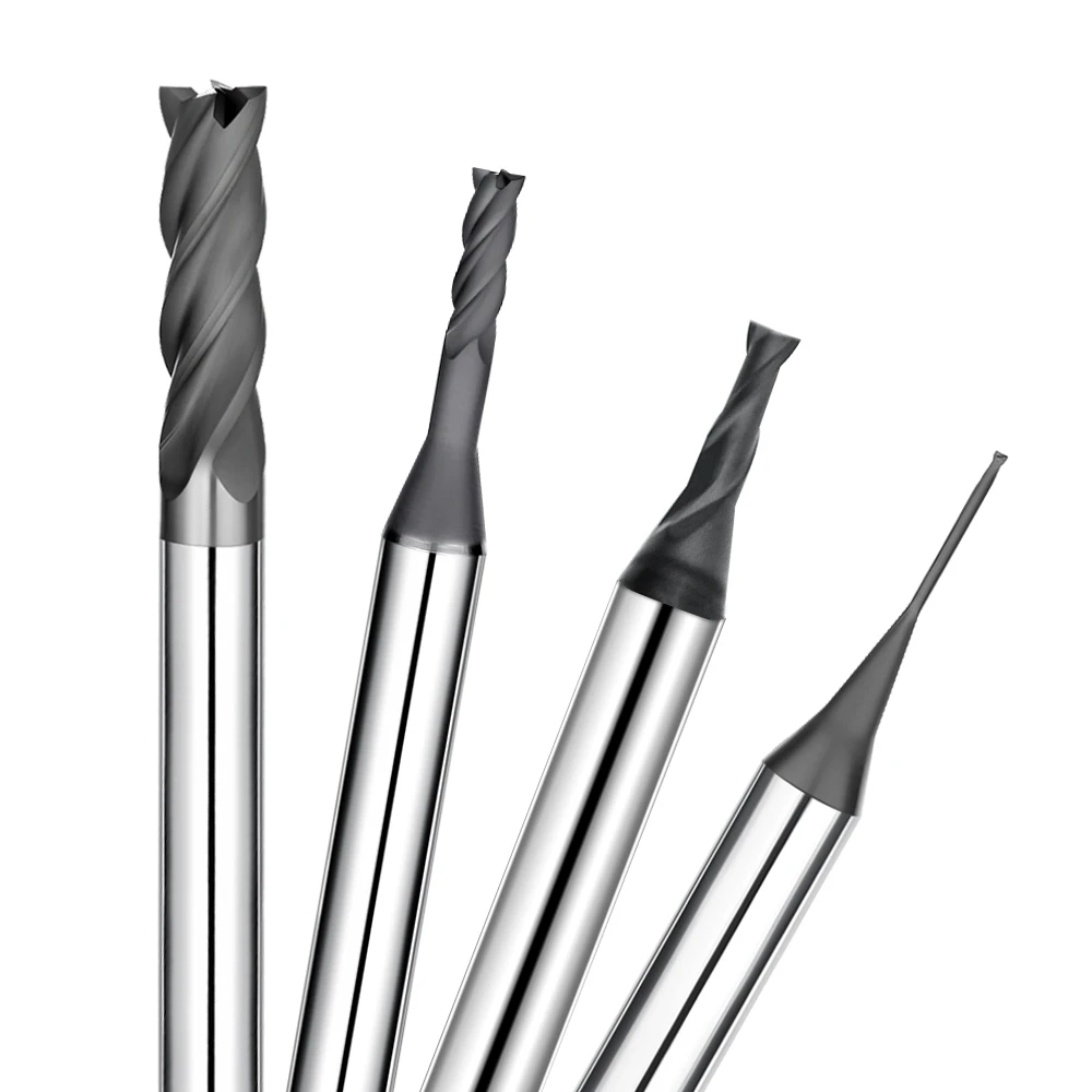
Feeding end mill bits for steel vertically downward—like a drill bit—is essentially defying the laws of physics. Milling geometry isn’t designed for vertical chip evacuation. Plunging forces chips into a confined space, causing heat and pressure to skyrocket instantly. We tell our customers: unless it’s a very specific scenario, always use Helical Interpolation or Ramping.
Angled entries allow the load to increase gradually, providing a buffer for the coating and the substrate. Our lab tests show that a ramp angle of 1.5° to 3° can extend tool life by nearly 30% compared to a straight plunge. If your end mills for steel are chipping before they’ve even started the actual cut, check your G-code. You might be asking the tool to bear an impossible initial load.
Edge Chipping from Imbalanced Radial (Ae) and Axial (Ap) Depths
When it comes to the Ap to Ae ratio, we advocate for a “material-specific” approach. In high-hardness steels, many operators stick to the old-school strategy: large Ae (width) and small Ap (depth). This is often the wrong choice for modern carbide end mills. Large radial engagement increases the “wrap” around the tool, trapping heat and causing thermal cracks. We prefer a “tall and slender” strategy: use more of the flute length (high Ap) and a much smaller radial step-over (low Ae).
This approach leverages the “chip thinning” effect, which reduces the load on each individual tooth. However, be careful—blindly increasing Ap without considering your spindle’s torque can lead to heavy chatter. In one mold-steel project, we dropped the Ae from 50% to 10% and increased the Ap to 1.5x the diameter. The chipping issues vanished instantly. Finding this balance is an art, but an imbalanced setup is a death warrant for your edge.
The Impact of “Air Cuts” and Re-entry in Trochoidal Milling
Trochoidal milling (high-speed machining) is popular, but operators often ignore the forces during entry and exit. When high-performance roughing end mills transition between “air cuts” and the material at high feed rates, every re-entry is a high-frequency impact. If your CAM software doesn’t use a smooth, arcing transition, the tool undergoes “rapid start-stop” loading. This is a nightmare for brittle carbide.
We’ve even seen cases where aggressive retraction speeds cause the tool to flick against the workpiece due to inertia. This “invisible” damage accumulates until the edge visibly chips. If your tool life is shorter than expected, look at your dynamic toolpath settings. Those high-speed reciprocating motions need smooth curves, not abrupt linear entries, to save your tool.
Cooling and Chip Evacuation: Real-World Debates on End Mills for Steel
The “coolant on or off” debate never ends in the shop. For carbide end mills, coolant does more than just lower the temperature; it provides lubrication and helps clear chips. However, in hard steels, the wrong cooling strategy can actually act as a catalyst for failure. Many operators aim the nozzle at the tool body, but at high RPMs, centrifugal force flings the water away. This leaves the edge in a dangerous “wet-dry” cycle.
Efficient chip evacuation is the “golden rule” for uninterrupted machining. If chips aren’t cleared immediately, they pack into the flutes and ruin the tool’s geometry. We’ve found that the stress from uneven heat dissipation is often more destructive than the heat itself. Before you turn on the pump, evaluate your evacuation space. Don’t just assume “more is better.”
Thermal Shock from Intermittent Cooling: The Case for Dry Cutting
When machining steel over HRC 45, we often recommend switching off the coolant and using a high-pressure air blast instead. Carbide substrates are heat-resistant but hate temperature swings. When an edge hits 800°F in the cut and is instantly doused with cold coolant, it creates “thermal shock” cracks. These cracks propagate quickly into large chips under mechanical stress.
In one mold shop, we tripled a tool’s lifespan simply by switching from flood coolant to air. With a high-quality heat-resistant coating, dry cutting allows the heat to leave with the chips. This keeps the tool edge at a stable temperature. If you see fine, transverse cracks at your tool tip, turn off the water. Give your tool a stable thermal environment.
Recutting: How Chip Accumulation Ruins Elite Steel End Mills
The worst sound in a shop is the “clicking” of chips being recut. Even the best end mill bits for steel will fail in seconds if they start crushing old chips. When chips aren’t cleared and get swept back into the gap between the tool and the part, the compressive forces skyrocket. This is why tools often fail in deep slots or pockets.
We often see “built-up edge” (BUE), where chips fuse to the cutting edge. This ruins the surface finish and destroys the tool’s ability to cut. To avoid this, program your toolpaths to account for chip flow—use gravity or high-pressure air to guide them away. Remember: your tool is a slicer, not a chip grinder.
The Vital Role of Through-Coolant in Deep-Cavity Steel
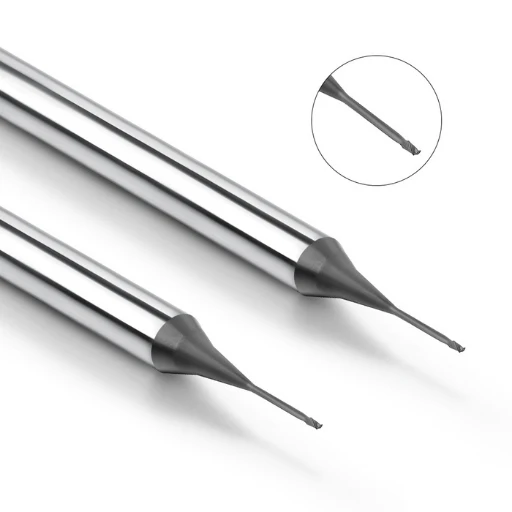
For deep cavities (depth-to-diameter over 3:1), external nozzles are mostly decorative. This is where roughing end mills with internal coolant (through-coolant) are game-changers. High-pressure coolant jets from the tool tip, providing precise cooling and—more importantly—an “inside-out” force that blasts chips out of the hole.
We tested this on a 50mm deep 304 stainless part. The external coolant setup broke the tool halfway through due to chip packing. The through-coolant setup finished the job with “silky-smooth” precision. We strongly recommend investing in through-coolant spindles and tools. The higher price pays for itself the first time you avoid a scrapped part or a broken tool deep in a cavity.
So, when you’re looking at that deep, narrow pocket, are you going to keep stopping to blow out chips, or are you going to switch to a real pressure-management solution?
As a Carbide End Mill Manufacturer, How We Suppress Chipping Through Geometry
In the R&D lab, we aren’t just grinding a tool to a sharp point. We are using geometry to “tame” the massive stresses of metal cutting. As a carbide end mill manufacturer, we know that while carbide is incredibly hard, its brittleness means it has zero tolerance for vibration. If we only improved the raw material without innovating flute design, edge chipping would remain an unsolved problem.
We’ve seen many general-purpose tools fail in alloy steels because their uniform geometry triggers physical resonance. By fine-tuning the ratio between the Rake Angle and the Relief Angle, we strengthen the edge while keeping the cut smooth and free. This micron-level balance ensures that cutting forces are directed toward the tool’s strongest structural axis, preventing the stress concentrations that cause fragmentation.
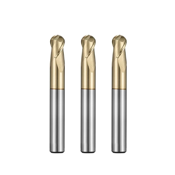
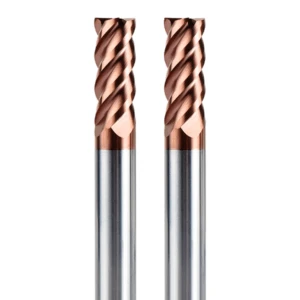
The Power of Variable Helix Angles to Stop Chatter
Our most potent weapon against “chatter” (that high-pitched whistling) is the variable helix design. Traditional end mills for steel with a fixed helix angle hit the material at a constant frequency. This creates harmonic vibrations, leading to wavy finishes and chipped edges. By alternating helix angles (for example, between 35° and 38°), we disrupt that rhythm. Because each tooth enters and exits at a slightly different time, the cutting forces are staggered, effectively killing resonance.
We recently helped a client machining automotive gears. By switching them to a variable helix series, we cut vibration feedback by 40%. The micro-chipping they were seeing on the side flutes vanished. This design is a lifesaver for deep slots or long-overhang jobs. If your shop floor sounds harsh and unstable, a geometric vibration-damping strategy is usually more effective than just chasing spindle speeds.
Edge Reinforcement: Why You Need Honing (Passivation)
A common mistake among new technicians is thinking “sharper is better.” From a manufacturer’s view, a “razor edge” is actually a jagged, unstable mess under a microscope. In tough steel, these paper-thin edges can’t handle the thermal and mechanical shock of the first cut—they simply shatter. That’s why we “hone” or passivate our end mill bits for steel. This process polishes the edge into a tiny, controlled radius.
A honed edge also provides a much better “anchor” for surface coatings. On our lines, we calibrate this radius (usually 0.02mm to 0.05mm) based on the application. It might feel slightly less “crisp” at first touch, but the impact resistance is vastly superior. If your brand-new tool fails in the first five minutes, it likely didn’t have enough edge reinforcement.
Matching Coatings and Substrates for Hardened Steels (> 45 HRC)
When you’re cutting steel over 45 HRC, the substrate grain size and coating formula must be perfect. For these extreme cases, our roughing end mills use sub-micron or nano-scale grains to maintain strength at high temperatures. We then pair them with AlTiN or nano-silicon coatings. During the cut, these coatings form a dense aluminum oxide layer that acts as a heat shield for the tool body.
We once consulted on a die-casting mold repair where the client only cared about “hardness.” The coating was so hard it didn’t match the thermal expansion of the substrate, causing it to flake off and take the cutting edge with it. Harder isn’t always better; the key is “toughness matching.” We fine-tune the cobalt content to give the substrate a bit of “spring” or elastic resilience. That synergy is what keeps the tool in one piece in extreme environments.
Engineer’s Summary: A Checklist to Stop Carbide End Mill Chipping
We’ve covered a lot of “pitfalls,” so let’s boil this down to a checklist you can take to the shop floor. When troubleshooting carbide end mills, we always advocate for a “subtractive” approach: eliminate the basics first. Chipping is rarely caused by obscure theories; it’s usually a loose bolt, a bad holder, or a sudden load spike in a corner.
This is the same logic we use when we help clients salvage expensive parts. Treat these not as rigid rules, but as a framework for your specific setup.
-
If you have unpredictable, random chipping: Check your spindle runout and holder precision. For end mills for steel, a runout of just 0.0008″ (0.02 mm) forces one edge to do all the work. Fix this before you change any other parameters.
-
If you’re roughing at high MRR and the tool breaks: Look at your entry path. Switch from a vertical plunge to a helical or ramped entry. If the chipping moves from the bottom of the tool to the side, you’ve successfully identified an impact load issue.
-
If you see tiny thermal cracks on the edge in hard steel: Turn off the liquid coolant and switch to a high-pressure air blast. Maintaining a stable temperature in the carbide end mills substrate is often more effective than buying a more expensive tool.
-
If your surface finish is rough and edges are chipping on long reaches: Re-evaluate your overhang. If you can shorten the tool by just 0.200″ (5 mm) while still hitting your depth, do it. The jump in stability is massive.
-
If you’re milling deep cavities or slots: Check for “recutting.” If your chips are different colors or look like powder, your roughing end mills are grinding old chips. Crank up the through-tool coolant pressure or optimize your toolpath to keep the cut clean.
As fellow engineers, we know every B2B project is different. No “universal parameter” covers every grade of steel. Every tool we grind in our lab faces its real test on your machine.
If you’ve gone through this list and the chipping is still baffling you, let’s talk. Send over your blueprints, material specs, or macro photos of the failed edges. Sometimes the best fix comes from a direct conversation between two people who know the sound of a bad cut.
In your shop right now, which part of this checklist hits closest to home?