


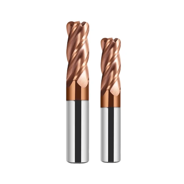
Last week, we sat down with a long-term aerospace client in Ohio. Their supervisor pointed to a pile of end mill roughing cutter units in the tool crib and just shook his head. Instead of standard flank wear, these tools were riddled with irregular chipping; some had lost a third of their cutting edge.
This scenario is far too common. Over 15 years in our own production lines and global field support, we’ve seen this disaster play out repeatedly. Pushing feed rates to the limit is great for efficiency, but a sudden chip-out is a nightmare. It ruins the tool and leaves carbide fragments in the part, which usually destroys the next finishing tool and scraps high-value workpieces.
We know that in heavy-duty roughing or High-Efficiency Milling (HEM), the balance between chip evacuation and impact force is razor-thin. When a shop sees chipping, the first instinct is to blame the wholesale carbide end mill quality. However, as manufacturers working with high-rigidity geometries every day, we know the root cause is rarely that simple.
Chipping happens when mechanical impact or thermal stress hits the carbide substrate’s breaking point. If you use a standard end mill cutter 4 flute but ignore chip compression in the flutes—or skip the specific micro-honing needed for an hrc65 milling cutter—you are essentially planting a ticking time bomb on your tool edge.
To fix this, we often re-evaluate the entire process. We frequently recommend switching to a bullnose milling cutter to distribute stress away from sharp corners while aggressively correcting spindle runout. Success isn’t luck; it’s about hunting down the “invisible killers” in your shop. Is your chipping caused by evacuation issues, or has your tool holder quietly drifted out of tolerance?
16 Years of Field Diagnostics: The Four “Invisible Killers” Causing Abnormal Chipping
In the shop, we say a tool either dies of “natural causes” (normal wear) or a “violent accident” (catastrophic chipping). When an operator pulls a shattered tool, they usually blame material hardness or tool quality. As engineers, we know these excuses often mask deeper systemic issues. Roughing is brutal on equipment, and the real culprits are usually hidden variables in the toolpath or system rigidity.
Our data from thousands of field tests shows that most chipping stems from four specific dimensions. When you push MRR to the limit, any weakness in evacuation, resonance, thermodynamics, or spindle precision will break the tool edge. We are going to dissect these “invisible killers” to help you find the technical leaks currently killing your shop’s profit margins.
Secondary Cutting and Jamming Caused by Insufficient Flute Clearance
We recently assisted a client roughing deep slots in heavy machinery bases. From the spindle side, we saw that the chips weren’t curling out; they were packing into a tangled mess. When the end mill roughing cutter rotated back around, it was forced to “re-cut” those work-hardened chips. This instant mechanical compression exceeded the carbide’s strength, shattering the edge in milliseconds.
Slotting and deep-cavity work are the most dangerous zones for chip packing. Engineers often chase depth of cut but forget the dynamic volume of the chips within the wholesale carbide end mill flutes. If the geometry lacks enough clearance or chips stick due to heat, the resulting impact is devastating. It won’t just chip the edge—it can snap the entire tool at the shank.
Low-Frequency Resonance and Mechanical Shock from System Rigidity Issues
Last month, we visited a shop machining stainless structural parts and heard that classic “piercing screech” from the 4-axis center. That resonance creates chatter marks and kills tools fast. In this case, thin workpiece walls and excessive tool overhang destroyed the system’s dynamic rigidity. Every time the edge engaged, it took a “hammer blow” that made the carbide highly susceptible to micro-chipping.
Impact resistance is the “make or break” factor for successful roughing. When resonance hits, cutting forces can fluctuate by hundreds of kilograms instantly. To fight this, we manufacture our end mill cutter 4 flute with variable helix and pitch to disrupt harmonic cycles. However, if your fixtures or hydraulic holders are weak, even the best tool can’t overcome a lack of system rigidity.
Instantaneous Thermal Shock and Crack Propagation from Improper Cooling
We’ve seen countless tools shattered by flawed cooling strategies, especially when machining low-conductivity alloys like Titanium. The cutting zone can hit 1,000°C in seconds. If an operator sprays coolant on a high-speed tool, centrifugal force keeps the liquid away until the edge exits the cut. This creates a “quench and heat” cycle that tears open micro-cracks in the coating and substrate.
Once thermal micro-cracks form, they propagate along grain boundaries under the stress of the next cut. We’ve used microscopy to see these “domino-effect” collapses on many retired tools. For high-speed roughing, we strongly suggest using high-pressure Air Blow or MQL. By avoiding the “thermal shock” of traditional wet cooling, you can significantly extend the life of your hrc65 milling cutter.
Uneven Loading Caused by Spindle Runout During High-Hardness Machining
In precision mold shops, runout determines if you win or lose. We once saw a project machining HRC60+ blocks where the hrc65 milling cutter chipped in under 10 minutes. We put a dial indicator on their spindle taper and shrink-fit holders, finding a 0.015 mm cumulative runout. In the world of ultra-hard machining, that much runout is a guaranteed disaster for any carbide tool.
When runout exceeds tolerance, the actual feed per tooth (Fz) becomes unbalanced. The edge on the “high side” takes double or triple the intended load, while the other side barely grazes the part. This asymmetrical loading causes the burdened edge to fail via mechanical overload. If you are working with hard materials, your tolerance for runout disappears, making clamping precision your top priority.
From Roughing to Residual Stock Cleanup: How to Optimize End Mill Roughing Cutter Lifespan Through Fracture-Resistant Geometric Design
When facing premature tool failure, many process engineers spend all their time tweaking speeds and feeds. However, our 16 years in tool R&D proves that if your cutting edge geometry isn’t tailored to your specific workpiece condition, parameter adjustments are just temporary band-aids. Throughout the entire cycle—from roughing to residual stock cleanup—the tool battles extreme radial forces and varying material allowances. We solve this by modifying the physical shape of the cutting edge, redirecting stress away from the fragile tip and deep into the robust core of the substrate.
Managing macro-stresses through micro-geometric design is our go-to strategy during on-site technical interventions. Every minute change in tool angles—from cross-sectional core thickness in slotting to the tip’s entry model—is magnified hundreds of times under high-speed machining. Let’s break down how specialized flute layouts, corner radius transitions, and micro-edge treatments give an end mill roughing cutter the structural integrity to turn brutal residual cleanup into a reliable, efficient process.
Why We Recommend a 4-Flute Structure for Enhanced Resistance to External Impact Forces Under Heavy Cutting Loads
During a heavy-duty valve body roughing project, a shop initially chose a 2-flute cutter to maximize chip clearance. However, deep axial cuts caused massive radial resistance, leading to frequent brittle fractures across the tool’s primary load zones. We analyzed the failure and stepped them up to a higher flute density. Increasing the flute count while maintaining the same outer diameter instantly expands the tool’s core diameter, creating a beefier cross-section that stops fatigue breakage from heavy bending moments.
The trick is balancing chip evacuation space with this newfound structural rigidity. We recommend an unequal-pitch, end mill cutter 4 flute configuration for heavy-duty setups because it ensures continuous, stable material engagement through every rotation. This layout distributes the peak mechanical load across more cutting edges while the variable-helix design dampens the harmonic vibrations of interrupted cuts. This balance allows your machining system to maintain extreme stability, even at aggressive axial depths of cut (Ap).
Utilizing the Bullnose Milling Cutter’s Rounded-Corner Design to Replace Sharp Edges and Prevent Corner Chipping
During 3D cavity roughing and pocket corner cleaning, standard square-shoulder end mills consistently develop micro-chipping at their sharp 90-degree tips. We recently inspected a die-maker’s retired tools under high magnification and saw massive stress concentrations right at the sharp points. Because a sharp corner lacks mass, simultaneous axial and lateral forces crush it instantly. Replacing that weak 90-degree intersection with a smooth radius is the fastest way to mitigate stress-induced edge failure.
Switching to a bullnose milling cutter with a dedicated corner radius completely changes how cutting forces travel through the tool. The radius disperses the mechanical shock across a smooth curve, moving the load away from a single point and into the thick transition zone between the side and bottom edges. This extra metal mass at the tip significantly boosts resistance to thermal and mechanical shock. It also eliminates the dangerous “catch-and-chatter” effect when cleaning out tight corners, protecting your most vulnerable cutting zones.
Process Control for Negative Chamfering and Micro-Edge Honing on HRC65 Milling Cutters for Machining Ultra-Hard Materials
When milling quenched die steels like H13 or D2, micro-edge geometry dictates whether your tool survives its first pass. We often see less-experienced programmers try to cut hard materials with a razor-sharp edge, only for it to shatter within seconds of engagement. In ultra-hard milling, an unhoned, sharp edge lacks the structural backing to survive immense compressive forces. That is why the final stage of our manufacturing process involves a strict micro-edge passivation protocol for every hrc65 milling cutter.
Our edge prep combines negative chamfering (K-land) and micron-level edge rounding (honing) via 5-axis grinding equipment. This micro-honing transforms a fragile, sharp edge into a micro-scale wedge. While this geometry slightly increases initial cutting resistance, it forces cutting heat into the chips rather than the tool body while providing incredible resistance to chipping. In high-hardening applications, this micron-level edge control is our primary defense against thermal-brittleness fractures.
The “Golden Rigidity Ratio” of Radial Depth of Cut (Ae) and Axial Depth of Cut (Ap) in Slotting and Side Milling
How a shop splits its Ae and Ap parameters shows how well its team understands process rigidity. We once troubleshooted a titanium structural project where the shop used a traditional full-slotting strategy with a shallow axial depth. The massive radial forces caused severe torsional vibration and immediate edge chipping. We resolved this by supplying a custom wholesale carbide end mill engineered with expanded chip flutes, paired with a HEM path using deep axial engagement (High Ap) and small radial steps (Low Ae).
Altering your Ap-to-Ae ratio fundamentally changes the forces hitting your tool edge. In full slotting (Ae=1D), the arc of engagement is 180 degrees, maximizing chip evacuation resistance and requiring a shallow axial depth to avoid tool deflection. Conversely, high-efficiency side milling drops the radial engagement to 10% or 15% of the tool diameter. Even though Ap increases to 1.5D or 2D, the tiny contact arc lets heat escape instantly with the flying chips, keeping your edge cool and preventing catastrophic failure.
Real-World Workshop Case Study: A Checklist for On-Site Parameter Adjustments Following the Adoption of High-Efficiency Roughing End Mills
Testing a tool’s lifespan in a laboratory cleanroom means nothing if it can’t survive on a real shop floor in the American Midwest or Stuttgart. We have audited dozens of machine shops and found a recurring theme: even with premium tooling, if the “speeds and feeds” sheets aren’t tuned to the machine’s actual wear, the spindle’s torque curve, and the material batch hardness, you lose 40% of the tool’s capacity. Roughing isn’t a crude hacking operation; it’s a precise thermodynamic balancing act.
Through these field turnarounds, we developed a dynamic optimization checklist. Cutting parameters are never static numbers—they are fluid strategies that adapt to machining feedback. When you upgrade to a high-performance end mill roughing cutter, your first step must be recalibrating the entire system’s safety boundaries. This means tracking everything from spindle vibration to chip color. The following three real-world cases show exactly how we adjust parameters on-site to secure maximum efficiency.
A Heavy-Duty Roughing Case Study with a German Automotive Mold Client: Dynamic Correction of Surface Speed (Vc) and Feed Per Tooth (Fz)
At a toolroom near Frankfurt, a client was roughing out a massive automotive body panel die from P20 pre-hardened steel. The shop floor reported a deafening screeching noise and highly irregular edge wear. We jumped on-site and checked the chip morphology; the deep blue color and thin profile proved their surface speed (Vc) was too high, causing severe friction and plastic deformation. We immediately lowered the surface speed by 15% and increased the feed per tooth (Fz) to form a thicker chip that could absorb and carry away the heat.
This adjustment targets the ideal balance between thermal loading and mechanical force. For high-volume, premium wholesale carbide end mill batches, excessive spindle speed acts as a poison that cooks the cobalt binder. Conversely, stepping up the feed rate stabilizes the cutting path and thickens the chip to shield the edge from thermal saturation. This quick correction silenced the chatter and boosted their metal removal rate by 30%, proving that chasing raw RPM rarely equals true machining efficiency.
Optimized Trochoidal Milling Paths for HEM of Aerospace Titanium Structural Components
Milling aerospace titanium (Ti-6Al-4V) is notoriously difficult. At a tier-one subcontractor in Seattle, their main headache was instantaneous tool chipping whenever the cutter hit a corner. Traditional toolpaths caused the tool’s arc of engagement to spike in tight spaces, overloading the teeth. We introduced an HEM strategy using optimized trochoidal toolpaths to ensure our end mill cutter 4 flute maintained a perfectly constant average chip thickness, eliminating sudden load spikes.
We focused heavily on the entry and exit transitions, implementing smooth “roll-in” entries via CAM software. By limiting the tool’s maximum contact arc to between 15 and 30 degrees in tight zones, the cutting edges spent ample time in the air to cool down during every rotation. This simple path adjustment drastically reduced the rapid oxidative wear common to titanium. For long-term production, optimizing your path profile always beats simply cranking up parameters on an outdated, abrupt toolpath.
How Switching from Flood Coolant to Dry Machining with Air Blow Saved High-Temperature Alloy Tool Tips
Many shops dealing with nickel-based superalloys or materials over HRC55 automatically flood the machine enclosure with full-pressure emulsion. However, at a facility milling aerospace turbine disks, we had the operators turn the coolant pump completely off. At high speeds, the liquid cannot penetrate the high-pressure zone at the edge; instead, it strikes the tool intermittently, causing brutal thermal shock. This constant heating and quenching makes the coating on an hrc65 milling cutter flake off like fish scales.
We swapped the fluid for a high-volume compressed air blast paired with MQL to clear hot chips and manage heat. The operators were nervous about running dry, but the results spoke for themselves. Eliminating the liquid stopped the thermal micro-cracking, preserving the carbide core’s natural toughness while the air blast kept chips from being re-cut. When your tool life drops unexpectedly under tough conditions, do you have the courage to shut off the coolant and let the air do the work?
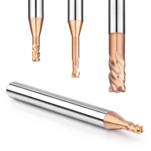
Avoiding Hidden Supply Chain Pitfalls: Why Choosing High-Quality Wholesale Carbide End Mills Can Prevent Cutting Edge Chipping at the Source
In our years in the tooling industry, we have realized a hard truth: 80% of inexplicable tool chipping happens before the tool ever touches the spindle. Many purchasing managers focus entirely on unit price, completely overlooking the hidden costs of cheap carbide. As manufacturers, we buy raw rod stock too, and we know the massive quality gap between discount rods and premium brands. Running a heavy-duty roughing cycle with cheap tools is like forcing an injured athlete to run a marathon; no parameter tuning can save a tool with a flawed substrate.
Supply chain transparency directly dictates your workshop’s process stability. The true value of a premium wholesale carbide end mill vendor isn’t a flashy logo; it is the brutal quality control built into their production line. Every step matters—from the purity of the virgin powder formulation to the exact density achieved during vacuum sintering. Any shortcut in the manufacturing process eventually shows up as a catastrophic failure on your CNC spindle. Let’s expose the raw material, grinding, and coating pitfalls that cause tools to die early.
How Microporosity and Grain Inhomogeneity in Substandard Carbide Raw Materials Manifest During Medium-to-Heavy Rough Machining
We have run metallographic cross-section tests in our lab on several low-cost import tools. The microscopic views were shocking: the interiors of these cheap rods were riddled with microporosity and massive, uneven cobalt pools. When you push an end mill roughing cutter made from this material into a heavy roughing cycle, cutting stresses concentrate directly on these voids. It is like building a skyscraper on a cracked foundation; under heavy loads, these micro-pores instantly turn into crack initiation sites, causing the edge to blow out.
Non-uniform grain size is another silent efficiency killer on the shop floor. High-quality tungsten carbide requires a perfectly uniform, sub-micron grain structure to balance hardness and toughness. Low-grade rods, suffering from outdated sintering cycles, exhibit erratic grain distribution that creates weak zones across the tool. When you push cutting speeds to the limit, these coarse-grain areas suffer rapid fatigue spalling. That is why we tell our peers to audit their supplier’s raw material source before signing a bulk contract.
Evaluating the Polishing Process on 5-Axis CNC Grinders: The Direct Impact of Flute Surface Roughness on Chip Evacuation Velocity
Many machinists assume cutting performance depends entirely on the sharp outer edge, but flute surface finish is just as critical. We ran a head-to-head test for a client using two tools with identical geometry. The only difference was that one end mill cutter 4 flute received an extra high-precision flute polishing step on our 5-axis grinders. That polished tool achieved a 40% jump in tool life during deep slotting. A mirror-smooth flute drops the friction coefficient, letting red-hot chips slide out effortlessly rather than packing and nesting.
When a manufacturer rushes tool production by over-feeding the grinding wheel, it leaves deep microscopic ridges inside the flutes. When milling gummy materials like stainless steel or aluminum, these rough grinds act as anchor points that trap evacuation chips. Once chip velocity drops, intense heat builds up in the flute, cooking the cutting edge and causing immediate failure. We highly recommend inspecting your bulk tool shipments under a loupe; a clean, polished flute is a hallmark of a tool built for heavy material removal.
Our Hardness Testing Standards for Anti-Peeling Composite Nano-Coatings on Wholesale Carbide End Mills
Coating technology is the ultimate body armor for modern tooling, but not all coatings are created equal. We constantly see tools marketed with “space-age coatings” that peel off like cheap automotive paint after three minutes of cutting hardened steel. In our facility, we prioritize coating adhesion strength over raw hardness during quality checks for our wholesale carbide end mill batches. If the atomic bond between the PVD layer and the carbide substrate fails, even a diamond-hard coating becomes useless under heavy friction.
To handle extreme applications over HRC 55, we rely on multi-layer composite nano-coatings that block micro-cracks from penetrating the carbide core while maintaining red-hardness at 1,000°C. We test these layers against the strict adhesion standards required for an hrc65 milling cutter using aggressive scratch and indentation methods. A quality coating should wear down gradually and uniformly, turning dull over time. If your coating is flaking off in large chunks, your supplier’s surface prep is failing, and your tool budget is taking the hit.
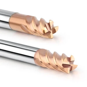
The 3-Minute Workshop Self-Checklist: When Your Roughing End Mill Chips Again
In a high-production CNC shop, downtime destroys profit margins. The moment you hear an ugly harmonic pitch from the operator station or spot sudden chatter marks on a part face, your tool has likely chipped. When an emergency hits the floor, we know the immediate instinct is to swap the tool, clear the alarm, and hit cycle start. However, if you don’t find the root cause of the edge failure, you are throwing money away. The next tool you install will almost certainly break in the exact same spot.
We created this quick 3-minute self-checklist so engineers can troubleshoot problems right at the machine enclosure. It requires no lab equipment—just your professional eyes and intuition. If you are battling recurring edge chipping or sudden tool snaps, use these three dimensions to reverse-engineer the failure. Investigating the crime scene saves your next end mill roughing cutter and gives you the data needed to permanently stabilize your production line.
Step 1: Stop the Machine and Observe the Chipping Morphology (Cold Cracking, Mechanical Chipping, or Thermal Fatigue)
Hit feed hold, pull the tool, and grab a magnifying glass to check the fracture face. If the chipped edge looks like jagged, shattered glass and failed the second it touched the workpiece, you are dealing with raw mechanical impact from excessive shock. However, if you are milling tough alloys and see a series of tiny vertical cracks along the edge, your tool is suffering from thermal fatigue caused by erratic temperature swings from your coolant lines.
This visual check gives you instant feedback on your cutting environment. If you see massive chunks missing or the entire core snapped, stop and check if your flutes are packing and re-cutting chips. Every unique wear pattern points to a specific mistake in the setup. If you aren’t sure how to read your tool’s wear geometry, or if you are struggling with a difficult material, send us a clear macro photo of the damaged edge; we can audit the failure mode together.
Step 2: Use a Dial Indicator to Verify the Static and Dynamic Runout of the Spindle and Shrink-Fit Toolholder
Often, tool failure has nothing to do with the cutter itself—the culprit is a worn spindle or holder. If you have gone through three premium tools and they all chip immediately, grab a 0.002mm indicator. Check the spindle taper runout first, then clamp the tool and check the runout at the nose. When running an hrc65 milling cutter, even a tiny 0.01mm dynamic runout deviation overloads a single tooth, causing it to take 200% of the intended chip load and breaking the tool.
If your static runout looks clean but the machine roars during a cut, check the balance of your tool holder or look for grease and fretting inside the bore. A worn-out holder acts like a blunt hammer on carbide tooling, destroying even the highest-grade cutters. If you are struggling with long-overhang setups or want to review your high-precision tool holding options, let’s talk about your fixturing rigidity. We can help you adjust your setup to handle these structural limits.
Step 3: Verify the CAM Software’s Entry Method (Ramp-in vs Plunge) and Deceleration Strategy
For the final check, head back to your programming workstation and look closely at your toolpath entry lines. If your tools consistently chip on the very first entry cut or snap right as they transition into a 90-degree corner, your CAM entry strategy needs work. Never plunge a heavy end mill cutter 4 flute straight down into material; always use a smooth helix or ramp-in path to gradually load the tool core. Also, make sure your software drops the feed rate inside tight internal corners.
If you are trying to maximize MRR but still using traditional linear toolpaths, it is time to step up to trochoidal milling or high-efficiency side milling. Modern CNC machining is won through smart software algorithms, not brute force. If your current CAM paths are hitting a wall, or you aren’t sure how to program proper step-overs for a bullnose milling cutter, let’s take a look at your part prints and optimize the workflow together.






