


Last month, we received an urgent email from a shop supervisor at a long-standing partner facility in Ohio. They were attempting to rough-machine a block of H13 mold steel using a standard carbide square end mill for steel. The tool suffered frequent micro-chipping and outright breakage in tight cavity corners and heavy, intermittent cuts. This broke the tool, left hardened carbide fragments embedded in the workpiece, and delayed their entire mold production line for two full days.
We see this exact scenario far too often in our 16-plus years of cutting tool manufacturing and on-site process optimization. When machining tough mold steels, many shops habitually reach for a conventional roughing end mill cutter. Alternatively, they opt straight for a flat-bottomed square end mill to get perfectly vertical walls in one shot. The inevitable result? Spiraling tool costs and constant machine downtime.
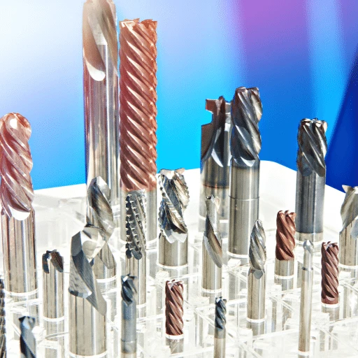
As a source manufacturer dedicated to high-quality china milling cutter tools, we have proven a hard truth across countless real-world projects: under harsh mold roughing conditions, a premium bullnose milling cutter is the true “King of Chip Resistance.” It is the one tool that genuinely safeguards your production output and your machine spindle.
We will skip the dry, textbook definitions today. Instead, let’s talk about the raw physics of cutting mechanics, tool-tip heat dissipation, and the grinding data we collect on our 5-axis machines. Why does switching to a radius-tipped tool allow your machine to rough high-hardness steels faster and more reliably?
Are you also enduring that nerve-wracking, ear-piercing chatter every time you rough-machine mold steel?

Starting with Urgent Calls from Western Clients: Why Do Square End Mills So Often Fail in Mold Steel?
Late one night, our technical support hotline rang. A stressed workshop supervisor from Stuttgart, Germany, was on the line. His team was racing to finish a batch of automotive front-grille die-casting molds. During the initial roughing pass with traditional flat-bottomed milling cutter bits, the sharp corners of the tools were chipping micro-fractionally. This erratic edge failure caused the spindle load to spike wildly. Worse, broken carbide fragments got packed into the bottom of deep slots, instantly destroying the next tool that hit them.
In our 16 years of large-scale tool manufacturing, we have fielded dozens of these desperate calls. When facing high-alloy, pre-hardened mold steels like H13, D2, or P20, many European and American programmers assume a square end mill saves time by cutting vertical walls in a single pass. They overlook how brutally these high-tensile, hot-hardened steels test a cutting edge during interrupted roughing cuts. A sharp-corner design creates a violent, rigid collision. This leads to high shop floor downtime and bleeding tool budgets.
The Structural Weakness of Sharp Corners: Stress Concentration in H13/D2 Machining
The instant a square end mill engages hard steel, the entire cutting impact converges on a sharp corner—a theoretical point with a radius of zero. During heavy metal removal, this tiny corner must handle simultaneous radial cutting forces and axial compression forces. These bidirectional stresses superimpose intensely at a single point. This easily exceeds the transverse rupture strength of the carbide substrate.
Compounding the issue is intense thermal load. Because the volume of metal at a sharp corner is minuscule, its heat dissipation capacity is incredibly poor. The cutting heat cannot escape into the tool body or the chips fast enough. Instead, it concentrates right at the cutting edge. This combination of mechanical and thermal shock degrades the tool tip’s hardness, causing micro-thermal cracks. This is why microscopic inspection always shows the corners failing first.
Why a Bullnose Milling Cutter Instantly Disperses Cutting Forces
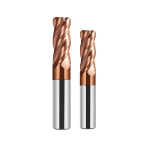
When we swap out a square tool for a bullnose milling cutter with a defined corner radius, the stress dynamics across the cutting zone transform completely. The continuous arc of the radius eliminates the sharp stress concentration point. The cutting forces are no longer focused on an isolated tip; they spread uniformly along the curved edge. This slashes the pressure per unit area, dramatically increasing the tool’s resistance to heavy shock loads.
The corner radius also changes your chip formation. At the same feed rate, the chip thickness thins out progressively across the radius profile. This inherent chip thinning effect unloads the machine spindle and dampens high-frequency harmonics. For your operators, the most obvious change is a massive drop in jarring chatter. The cutting action becomes incredibly smooth, providing the process reliability your shop needs.
German Case Study: Corner Chipping vs Radius Heat Dissipation
Let’s look back at our German client. To solve their chipping bottleneck, we supplied custom milling cutter bits engineered with an optimized R1.5 corner radius for high-hardness steels. We kept their core machining parameters virtually identical but updated their CAM toolpath to follow the contour smoothly. The feedback from their shop floor was an immediate relief; they eliminated the mid-cavity tool changes entirely.
When we compared the failed square tools to the used bullnose cutters, the physics were clear. The rounded nose provides a larger volume of carbide material directly behind the cutting edge. This mass acts as a thermal sink. During high-speed dry machining with air blast, heat conducts smoothly away from the cutting zone into the tool body. This prevents the localized thermal softening that ruins sharp corners. For heavy mold roughing, leveraging a radius for better stress and thermal management outperforms a square end mill every single time.
The Limitations of Traditional Roughing End Mill Cutters in Deep-Cavity Mold Steel Processing
In the eyes of many veteran CNC machinists, roughing large-to-medium-sized molds means reaching for a serrated roughing end mill cutter. Historically, when machining standard carbon steel or softer materials, this classic design excelled due to its unique chip-breaking flutes. However, as workshops transition to deep-cavity molds pre-hardened above 40 HRC, traditional serrated cutters reveal severe limitations and become an invisible bottleneck dragging down shop efficiency.
We frequently discuss deep-cavity machining with shop floor process engineers who face major challenges with tool stability and smooth chip evacuation. Running a serrated tool deep inside a narrow cavity with long tool overhangs induces high-frequency, periodic fluctuations in cutting forces. These mechanical vibrations amplify exponentially, triggering spindle resonance and making the tool highly susceptible to sudden jamming during heavy pocketing cuts.
Micro-Spalling Phenomena: Why Serrated Edges Fail in Pre-Hardened Steel (>40 HRC)
During tool-life trials at our testing center, we machined NAK80 pre-hardened mold steel at 45 HRC using a serrated roughing end mill cutter. High-magnification microscopic observation revealed that because its cutting edge is a continuous series of sinusoidal curves, it generates high-frequency shear forces. The crests of the wave profile take immense normal compressive forces, resulting in an uneven stress distribution across the tool’s rake face.
Compounded by rapid thermal expansion and contraction from intermittent cutting, this lopsided stress distribution rapidly induces micro-thermal fatigue cracks at the wave crests. On the shop floor, rows of minute micro-chipping appear along the tips of the wave-shaped edge, causing cutting resistance to rise exponentially. This inevitably leads to widespread coating delamination and the premature scrapping of the entire tool.
Metal Removal Rates (MRR) Compared: Wave-Edge Cutters vs. Bullnose Cutters
To provide solid data for our high-volume purchasing clients, we conducted a rigorous field trial on an automotive headlight mold production line. When running traditional wave-edge tools, the harsh impact forces from the hard material forced us to limit both the axial depth of cut (Ap) and feed per tooth. As a result, the MRR stagnated at a conservative plateau and proved extremely difficult to improve.
The situation completely reversed when we switched to a premium bullnose milling cutter optimized for hard steels and paired it with high-speed machining (HSM) CAM strategies. Even though a bullnose cutter lacks chip-breaking grooves, its unique geometry triggers a highly effective chip-thinning mechanism. This allows us to increase both cutting speed (SFM) and feed per tooth to 1.5 or 2 times the original values, boosting total MRR by over 25%.
Why We Recommend Large Corner Radius Bullnose Cutters for High-Rigidity Machining
As modern workshops upgrade to high-rigidity, high-spindle-speed CNC machining centers, we increasingly recommend a bullnose milling cutter with a large corner radius during technical consultations. The core logic lies in achieving a holistic balance of rigidity across the entire machining system. A large-radius bullnose cutter utilizes modern geometric principles to efficiently “peel” material away, redirecting a massive portion of the cutting forces from the radial axis into the more rigid axial axis.
This shift in force direction is critical for extending your machine’s spindle life and maintaining long-term machining precision. Simultaneously, the large-radius design provides the cutter tip with a much thicker carbide substrate for structural support against slag inclusions or inconsistent material hardness. Selecting large-radius bullnose cutters is the smartest industry consensus for modern, high-rigidity mold machining.
How We Design and Optimize the Geometric Parameters of Our Mold Steel Bullnose Cutters
Whenever clients visit our R&D center, they ask why bullnose cutters that look identical to the naked eye perform so differently when cutting hardened mold steel. The true essence of a high-performance tool lies entirely within its microscopic geometric parameters. On our production floor, manufacturing involves far more than simply grinding a radius onto a standard carbide blank; we must meticulously fine-tune the rake angle, relief angle, and core diameter ratios.
If you blindly prioritize sharpness by making the rake angle too large, you compromise the cutting edge strength, leading to chipping in hard steels. Conversely, if you over-emphasize strength by excessively dulling the cutting edge, cutting resistance skyrockets, triggering severe chatter. To strike the perfect balance between tool strength and cutting efficiency, we ran countless cutting trials while developing this specialized tooling line.
Core Technical Challenges: Precision Radius Tolerances and Variable Pitch Design
During the grinding process, our first major technical hurdle was achieving precise control over the geometric profile of the corner radius. Tools from standard manufacturers often exhibit minute “step” marks or subtle discontinuities where the corner radius meets the peripheral cutting edge. By upgrading the closed-loop control systems on our 5-axis grinding machines, we rigorously confine arc tolerances to an extremely narrow, micron-level range to eliminate premature chipping.
Beyond arc precision, we fully integrated Variable Pitch and Variable Helix designs into these specialized milling cutter bits. If you meticulously measure our multi-flute tools, you will discover that the angular spacing between adjacent flutes features subtle variations like alternating between 89 and 91 degrees. This variable pitch geometry disrupts periodic cutting impact frequencies, breaking up acoustic resonance and suppressing tool chatter at the source.
Selection Criteria for Premium Carbide Substrates and Ultra-Fine Micrograin Rod Stock
As the old adage goes, “even the cleverest cook cannot make a meal without rice.” No matter how perfect the geometric design, a tool will barely survive a few meters of cutting if the substrate fails to meet rigorous standards. When customizing high-quality milling cutter bits for our industrial clients, we employ an uncompromising screening process, exclusively relying on ultra-fine micrograin carbide substrates with an average grain size between 0.4 and 0.6 microns.
Under actual heavy-duty roughing conditions, the cobalt (Co) content directly determines the material’s toughness and wear resistance. Following extensive comparative field testing, we identified a specific “golden ratio” for the cobalt content in substrates used for roughing mold steels. This premium ultra-fine-grain substrate features microscopic grain boundaries that effectively inhibit the propagation of micro-cracks, preserving cutting edge integrity during heavy interrupted cuts.
Field Performance: Advanced AlTiN/nACo Nanocoatings for High-Speed Dry Machining
In modern mold manufacturing, we strongly recommend that clients employ dry machining techniques combined with air-blast chip evacuation. This prevents the high-frequency thermal stresses caused by rapid heating and cooling cycles from fracturing carbide tools. Under dry machining conditions, localized temperatures generated by friction between the tool tip and the workpiece surface can instantly skyrocket past 800°C, sometimes exceeding 1000°C.
To ensure our tools remain sharp under extreme thermal challenges, we apply a multi-layer composite coating—either AlTiN or a nanostructured nACo—to the cutting edge after passivation. Based on practical feedback, our premium china milling cutter tools demonstrate a resistance to flank wear that is more than 40% superior to standard-coated tools when machining hardened steel exceeding 50 HRC, proving the genuine strength of our surface engineering technology.
A Practical Guide for Western Workshops: How to Properly Program and Utilize These Milling Cutter Bits to Maximize Lifespan
We frequently see a regrettable trend in our technical support case library: Western purchasing managers meticulously select top-tier rotary cutting tools, only for them to fail on the shop floor. This underperformance typically stems from improper configurations in the CAM software or legacy habits carried over from machining older, softer steel grades. An excellent milling cutter bits line is only halfway to success out of the box; the rest depends entirely on the cutting data you input.
We consistently advocate for prioritizing tool protection as early as the toolpath generation stage when collaborating with frontline CAM programmers. Roughing operations should not merely aim for maximum metal removal rates, but rather for absolute stability in cutting forces throughout the cycle. If your toolpath results in momentary over-engagement at corners or excessively steep entry angles, even premium carbide will fail under the sudden shear stress.
Core Parameters: Adjusting Feed Per Tooth (IPT) and SFM Based on Mold Steel Hardness
When adjusting parameters, we advise against blindly adhering to the recommended values printed on tool packaging; instead, correlate settings with machine rigidity, spindle torque, and workpiece hardness. When working with pre-hardened mold steels like H13 or D2 (38–44 HRC), a delicate dynamic balance exists between cutting speed (SFM) and feed per tooth (IPT). Blindly reducing the feed rate causes severe rubbing, leading to a nasty work hardening layer that rapidly destroys the cutting edge.
The correct approach when using an end mill for steel is to apply chip-thinning compensation calculations based on the unique corner radius of the tool. Because the true chip thickness generated by a radius is significantly thinner than the programmed IPT value, you can moderately increase table feed to ensure the edge bites into the material. However, if the steel hardness exceeds 50 HRC, decisively reduce cutting speed by 20% to 30% while maintaining a stable, aggressive feed.
The Actual Wear Patterns of Round-Nose Cutter Bottom Edges During Helical Entry and Ramping Operations
Safely feeding a tool into solid mold steel is the most critical phase of roughing and heavily tests a programmer’s expertise. We strongly advise against any form of direct vertical plunging, as this subjects the center of the tool’s bottom edge to extreme compressive forces where chip evacuation is impossible. During continuous contouring operations, we recommend prioritizing either helical entry or ramping at a shallow angle to preserve your milling cutter bits.
During a helical ramp-down, the corner radius is subjected to dual stresses: a blind cut at the bottom and multi-directional loads from lateral engagement. Our microscopic analysis shows that if the helical ramp angle exceeds 2.5 degrees, the non-cutting center zone frequently rubs against the workpiece, causing built-up edge (BUE) formation. A low-angle linear ramp distributes forces more evenly, but high-pressure through-spindle compressed air is always required to prevent chip recutting.
Why the Calculation of Residual Height Directly Determines the Fate of Subsequent Finishing Tools
Many workshop supervisors focus solely on the cutting speed of the roughing tool while overlooking the erratic stock left behind for subsequent operations. After a roughing pass using a roughing end mill cutter or a large-radius tool involving large step-downs, the stepped surfaces retain a wave-like texture known as scallop height. If this residual metal stock is distributed highly unevenly, subsequent semi-finishing and finishing stages will face catastrophic tool failure.
Imagine a finishing tool spinning at high RPM encountering a massive metal step caused by an ill-planned roughing pass; the radial depth of cut instantly surges several-fold. This sudden impact load triggers high-frequency fractures within milliseconds, causing expensive tools to fail inexplicably during corner-cleaning operations. When guiding clients, we emphasize setting a reasonable scallop height between 0.2 mm and 0.5 mm in CAM to ensure the residual stock is perfectly uniform.

Unveiling Our “Hard Power” as a Chinese Cutting Tool Manufacturer: How to Choose a Reliable Supplier for China Milling Cutter Tools
Through years of technical exchange, we frequently sense the dilemma overseas buyers face when selecting supply chain partners. Native Western tool brands offer stable quality but carry high unit costs and lengthy lead times that severely squeeze your workshop’s profit margins. Conversely, when confronted with a vast array of Chinese suppliers, managers worry about inconsistent product quality, material instability, or tolerance deviations that increase scrap rates.
We firmly believe that the reliability of a china milling cutter tools supplier should not be judged by catchy PowerPoint marketing slogans. Instead, scrutinize them with the same rigor applied when inspecting workpieces: drill down into their manufacturing equipment, quality control protocols, and engineering depth. If you are experiencing inefficient machining on difficult steel components, use our factory standards detailed below as a benchmark to evaluate your supply chain.
Western Buyers’ Stereotypes Regarding Chinese Cutting Tools—and Our Rigorous Control Over Runout (Runout < 0.005mm)
To be frank, the old perception of Chinese rotary tools was stuck in a phase characterized by low-end quality, poor wear resistance, and soft-material limitations. However, modern high-end Chinese tool manufacturing has long since completed a comprehensive technological evolution. In many workshops, short tool life during hard steel machining is largely due to excessive radial runout, which causes a single edge to bear the vast majority of the load.
To shatter this stereotype, we have established an extremely rigorous, 100% inspection protocol for runout before any tool leaves our facility. Through specialized cutting-edge grinding processes and precision collet systems, we strictly limit the radial runout of every outgoing tool to less than 0.005mm. Only when runout is controlled at this micron level can every cutting edge of a multi-flute bullnose milling cutter achieve truly uniform load distribution.
How German 5-Axis Grinders (ANCA/Walter) and Zoller Measuring Systems Guarantee Quality
Hardware investment is the ultimate proof of quality; a sophisticated geometry design requires a top-tier multi-axis grinding machine to accurately reproduce it. Across our entire production line, we have fully integrated high-end 5-axis CNC grinding machines from Australia’s ANCA and Germany’s Walter. Powered by high-rigidity spindles and intelligent software, this elite equipment ensures that the rake angle, relief angle, and core diameter precisely match design specifications.
In the inspection phase, we utilize a German-made Zoller non-contact optical measuring system to guarantee the quality of every batch. Our quality control engineers perform 3D profile scans and comparisons of the tool’s corner radius and cutting-edge honing radius, ensuring tolerances do not deviate by a single micron. Only when backed by world-class machine tools and inspection equipment can our tools demonstrate a level of stability that easily rivals any leading international brand.
Our B2B Customization Process: How We Tailor Cutting-Edge Geometry to Specific Mold Blueprints for Western Clients (OEM/ODM)
Over sixteen years of providing on-site technical support, we have observed that fully standardized, off-the-shelf tools often struggle with unique workshop environments. Variations in machine rigidity, differences in cutting fluids, and even mold steels of the same grade from different master batches introduce subtle performance nuances. Consequently, we act as a technical partner capable of integrating deeply into your process chain rather than just a warehouse.
If you are currently facing the challenge of machining complex-surface molds or attempting to process novel, ultra-hard alloy steels, we invite you to contact us. You can readily exchange your machining conditions, part blueprints, or material hardness specifications with our team. Our engineers will work directly with your CAM programmers to fine-tune variable helix angles, cutting-edge sharpness, or customize unique non-standard length-to-diameter ratios before shipment.


