


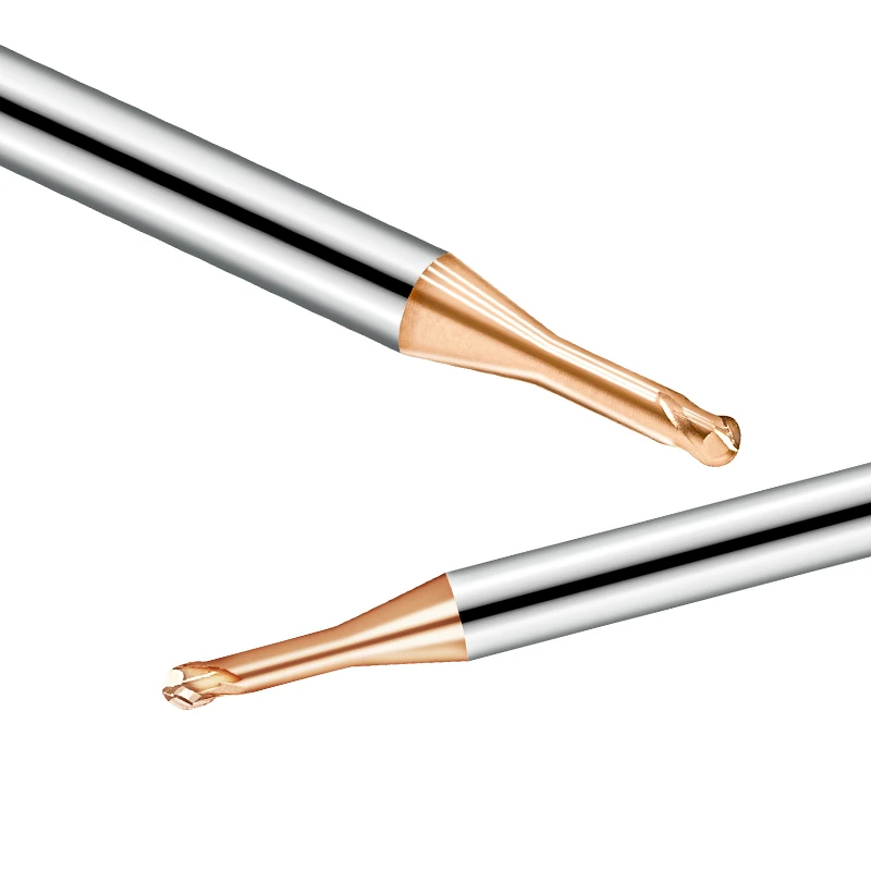
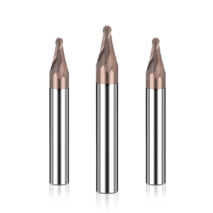
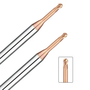
In the deep-machining zones of mold workshops, a common scene unfolds: a 4mm 2 flutes ball nose long neck milling cutter is buried in a narrow cavity rib exceeding 40mm in depth. The operator keeps a hand firmly on the feed override knob, listening with palpable tension to the faint whistling sounds coming from the spindle.
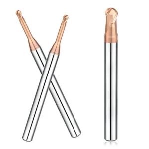
As a ball nose end mill cutter manufacturer, we are repeatedly asked one core question while supporting Tier 1 suppliers in the US and Europe: When facing deep-cavity steel, should you choose a straight neck or a tapered neck?
Many customers focus solely on the precision of the ball nose radius or the coating. They often overlook “neck rigidity”—the hidden factor that makes or breaks a project. We recently stepped in on an H13 mold steel project (HRC 48–52) where the client used a standard solid carbide ball nose milling cutter with a straight neck. The tool suffered from frequent deflection during corner-cleaning. This didn’t just ruin the surface finish; it caused micro-chipping that scrapped an expensive, nearly finished mold block.
With 16 years of CNC machining and manufacturing experience, we know that balancing “rigidity” and “clearance” is a mandatory lesson. While straight-neck tools offer versatility, they struggle to control chatter when cutting steel. A tapered neck ball nose milling cutter, with its geometrically increasing strength, is almost always the superior choice for high lateral cutting forces.
Should you prioritize maximum clearance, or optimize the neck taper to double your feed rates? Let’s look at the data.
Why Do We Advise Against Blindly Using Straight Neck Ball Nose Milling Cutters for Deep-Cavity Steel Machining?
In both our factory labs and our customers’ shops, the straight-neck ball nose milling cutter is often seen as a “universal solution.” Its simple structure seems to eliminate interference concerns in deep slots. However, when cutting steel with high hardness and resistance, this “universal” approach becomes an efficiency killer. We often see engineers slashing feed rates to 50% of the recommended values just to compensate for a lack of rigidity. In a competitive market, sacrificing 50% of your productivity for “safety” is not a sustainable strategy.
A ball milling cutter for cutting steel should not be chosen just because it can “reach” the bottom. In finishing operations, a straight-neck tool has the same diameter from the shank to the cutting edge. This means torsional resistance is constant and diminishes geometrically as the overhang increases. If you use a straight-neck cutter for depths exceeding 5xD (five times the diameter), you are pitting a fragile structure against extreme forces. This doesn’t just gamble with your yield; it kills your spindle life.
A Disparity in Rigidity: Assessing the Risk of Tool Breakage via the L/D Ratio
When the Length-to-Diameter (L/D) ratio exceeds 8:1, our reliability assessment for any solid carbide ball nose milling cutter becomes extremely rigorous. Carbide is hard, but it is highly susceptible to fatigue from high-frequency micro-vibrations. In deep cavities, a straight-neck cutter acts like a long lever. The torque generated at the tip is transmitted directly to the slender neck.
In our tests on P20 mold steel, a mere 0.02mm of radial runout was amplified into violent chatter at extended overhangs. This breakage is insidious; it often doesn’t happen immediately. After hours of machining, as the coating wears and resistance rises, the neck instantaneously exceeds its stress limit. If your path allows even a 1° to 3° clearance angle, a tapered neck tool is the best insurance for your workpiece. The cost of EDM-extracting a broken tool from a deep cavity far exceeds the price of a premium cutter.
Case Study: Addressing Tool Deflection and Chatter Marks in HRC40+ Steel
Last year, we helped a German automotive mold maker resolve corner-cleaning issues in H13 steel. The client used a standard 2 flutes ball nose long neck milling cutter but reported constant tool deflection. Even with light, layered cuts, the sidewalls showed visible, step-like chatter marks.
Our on-site observation found that even on a high-precision machine, the radial deflection caused the tool to deviate from the programmed CAD path. These errors are catastrophic in the finishing stage, as they require hours of manual polishing. We discovered that this chatter was a result of resonance—the tool’s natural frequency was clashing with the machine’s cutting frequency.
Because straight-neck tools have a fixed area moment of inertia, they have a lower natural frequency. You can’t always “tune out” that resonance just by adjusting RPM. As a specialized ball nose end mill cutter manufacturer, we’ve found that increasing tool rigidity—even marginally—is more effective than endlessly tweaking parameters. Changing to a tapered neck structure resolves the root cause: structural deficiency.
The Practical Advantages of a Tapered Neck: Enhancing Stability in Steel Ball Milling
In our years of technical support, we’ve found that switching to a tapered neck is often the turning point for resolving efficiency bottlenecks. The logic is simple: “exchange space for strength.” Whenever deep cavities or mold features with draft angles allow it, we consistently recommend a tapered-neck solution.
This design doesn’t just improve static rigidity; it fundamentally changes the tool’s damping characteristics. By altering the harmonic frequency, the taper suppresses the high-pitched chatter common when machining high-strength alloy steels. This makes the entire cutting process more robust and predictable.
From a manufacturing standpoint, our biggest concern with a ball milling cutter for cutting steel is deflection at the neck under lateral loads. A tapered design distributes cutting stress evenly across the tool body rather than concentrating it at a single vulnerable cross-section. In our tests on 45# steel, tapered-neck tools showed 35% less radial runout than straight-neck tools at the same overhang. This stability leads directly to a superior surface finish, drastically reducing the time you spend on manual polishing.
Stepped Rigidity: Reinforcing the Tool Root Against Lateral Forces
In extreme scenarios—like clearing tight corners in deep cavities—we focus on one thing: resistance to deflection. The beauty of a tapered neck is that it leverages an expanding moment of inertia. We call this “stepped rigidity.” When you use a solid carbide ball nose milling cutter for side milling or contouring, the reinforced root acts as a sturdy fulcrum. It counteracts the bending moments created by long overhangs in a way that software compensation simply cannot match.
We recently handled an automotive grille mold for a North American client. Because of an excessive overhang, the tool tip’s initial engagement was extremely poor. By switching to a slight 1.5° taper, we increased the bending strength at the root by an order of magnitude. Remember: tool rigidity strengthens geometrically, not linearly, with every 10% increase in root diameter. This geometric advantage ensures your complex contoured surfaces stay within strict design tolerances.
Optimizing Feed Rates for 2-Flute Ball Nose Long Neck Milling Cutters
In machining, rigidity is money. When using a 2 flutes ball nose long neck milling cutter in deep cavities, many operators adopt a “skimming” approach to protect the tool. However, the purpose of a tapered neck is to break that cycle of inefficiency. With superior structural support, you can confidently increase the feed per tooth (Fz) without fearing tool fracture.
In a project involving 316L stainless steel, we replaced a straight-neck tool with a tapered-neck version and optimized the trochoidal path. The result? We increased the feed rate by 40% while actually extending the tool’s service life. A stable cutting process minimizes friction and impact, allowing heat to escape through the chips rather than soaking into the tool. For large-volume steel orders, investing in the right neck geometry pays dividends in saved labor hours.
Clearance and Interference: Selecting the Right Ball-Nose End Mill for Tight Constraints
Clearing deep corners often presents a dilemma: you want the thickest neck for rigidity, but you need clearance for complex contours. When machining undercuts or steep slopes, the margin for error is often less than a millimeter. We’ve seen many engineers choose a high-taper tool for stability, only to have the shank crash into the sidewall midway through the program. Selecting a ball nose milling cutter for steel is a constant balancing act between cutting strength and the “red line” of interference.
Don’t rely solely on a catalog’s “overall length” (OAL). In the real world, spindle head dimensions, fixture height, and even coolant nozzles affect clearance. This is especially true in 5-axis or 3+2 machining, where a tilt angle can instantly eliminate your safety zone. We always simulate using our clients’ STP files. We would rather recommend a tool with slightly lower rigidity that can finish the path safely than risk a catastrophic collision that scraps a mold base.
Preventing Collisions Through CAD Simulation
We no longer rely on gut feeling for complex projects. We guide our clients to use CAD software for precise, dynamic toolpath simulations. When using a solid carbide ball nose milling cutter in “bottomless” cavities, your interference check must cover every orientation the tool takes. We recommend creating a digital model of the tool holder and defining a safety envelope (clearance buffer) of at least 0.1 mm to 0.2 mm.
This data-driven approach saves massive headaches. I recall a client who insisted on a large-angle tapered neck. Our simulation showed the shank would scrape the upper edge of the workpiece while sweeping the bottom radius. We compromised with a “step-neck” design instead. As a ball nose end mill cutter manufacturer, we want our users to have total confidence. All collision hazards should be eliminated on the screen—not discovered by the jarring sound of a crash in the spindle.
Narrow Slot Strategies and Chip Evacuation
When machining slots less than 2mm wide, chip evacuation determines your tool life. We pay close attention to the environment at the bottom of the slot. Deep in a narrow groove, coolant rarely reaches the tool tip effectively. If chips aren’t expelled fast, they get recut, leading to instant breakage. While a 2-flute design has less edge strength than a multi-flute tool, its massive flute space is a lifesaver for deep slots.
Most tool breakages we analyze are caused by chip packing, not excessive force. For narrow slots, we advise against “full slotting.” Instead, use trochoidal or step-cutting techniques. This allows the 2 flutes ball nose long neck milling cutter to leverage its clearance, moving chips smoothly up the helical flutes. In high-hardness steel, even small chip accumulations cause heat that triggers thermal fatigue in the carbide. Always inspect the grinding finish of the flutes; a smooth, polished flute is what keeps your deep-slot operations running without a hitch.
The Engineer’s Logic: When to Contact Your Ball Nose End Mill Manufacturer for Custom Specs
In an era where standard catalogs cover 90% of routine jobs, why go custom? As an engineer dealing with complex blueprints daily, I see many peers try to “muscle through” chatter or tool life bottlenecks by tweaking machine parameters. They rarely consider that the tool’s geometry itself is the problem. When you face extreme overhangs or steel grades that push standard coatings to their limit, a custom consultation with a professional ball nose end mill cutter manufacturer can save you from an endless cycle of trial and error.
We recently handled a high-volume mold insert project. The client’s standard tools required a tiny step-over to avoid neck interference, ballooning the cycle time to four hours per part. We intervened by redesigning the neck taper and reducing the shank diameter by just a few microns. While the per-tool cost rose slightly, the boost in rigidity increased efficiency by 30%. Intelligent tool selection isn’t just about buying a cutter; it’s about finding the geometry that optimizes your entire process chain.
Depths Exceeding 10xD: Matching Substrate and Coating for Solid Carbide Ball Nose Milling Cutters
When machining depths exceed ten times the diameter (10xD), the physics of cutting change completely. At this stage, choosing a solid carbide ball nose milling cutter becomes a contest of material science. The tool’s Transverse Rupture Strength (TRS) and grain size are critical. We often adjust cobalt content based on the steel grade. It’s a delicate balance: if the substrate is too hard, it snaps; if it’s too tough, it deforms. This balance is a lesson we’ve earned through years of analyzing failed tools.
Beyond the substrate, the coating must shift from “wear resistance” to “friction reduction.” At the bottom of a deep cavity, heat dissipation is nearly impossible. We use specialized composite nano-coatings that maintain a low coefficient of friction at temperatures exceeding 800°C. This prevents Built-Up Edge (BUE) and secondary cutting—both of which ruin surface quality. If you are running 10xD operations, ask your supplier for coating adhesion data. In high-vibration environments, delamination is the first sign of impending failure.
Standard vs. Custom: The Long-Term ROI of Tapered-Neck Tools
Procurement managers often ask: “Why pay double for a custom tapered-neck tool?” My answer is simple: “What does it cost when a standard 2 flutes ball nose long neck milling cutter snaps and ruins a €20,000 workpiece?” Or when tool deflection adds 10 hours of manual polishing for a bench technician? Standard tools are built for compromise. Custom tools are precision weapons tailored for efficiency.
Our data shows that a tapered-neck angle matched to your specific cavity slope allows the system’s resonant frequency to bypass the machine’s typical spindle speed range. This results in superior finishes and protects your spindle bearings. Conduct a cost-benefit analysis early: if a custom tool boosts life by 50% or ensures uniform finishing stock, the long-term savings will dwarf the initial price. Profitability comes from stability, not the lowest sticker price.
16 Years of Field Experience: A Selection Guide Based on Steel Hardness
After thousands of deep-cavity cases, we’ve learned one truth: there is no “best” tool—only the geometry that fits the conditions. When buying a ball milling cutter for cutting steel, your neck geometry determines your cutting load limit. For medium-to-low hardness steels (like NAK80 or 718H), a slight taper that prioritizes chip evacuation allows for faster feeds. For high-hardness tool steels, rigidity is everything. Our rule of thumb: “Taper over straight neck; short over long.” This eliminates 80% of sudden breakages.
We use this logic to balance machine stability with tool integrity. If you’re fighting surface chatter or inconsistent tool life, try fine-tuning your specs based on the data below. These aren’t lab numbers; they are “shop-proven” conclusions earned at the cost of actual material and machine time.
Vibration Mitigation for P20/H13 Steel: Recommended Taper Parameters
In mold manufacturing, P20 (HRC 30–38) and H13 (HRC 48–52) require different vibration strategies. For P20—which can be “sticky”—we recommend a 1.5° to 3° neck taper. Pair this with a solid carbide ball nose milling cutter featuring a high helix angle to balance rigidity with chip flow. For high-hardness H13, where cutting forces are extreme, increase the taper to 5° or higher if the geometry allows. This uses the tool root’s strength to kill high-frequency vibration.
If you still hear a “whistling” sound after adjusting your Speeds and Feeds, your neck design is likely hitting a resonance zone. Increasing the taper by just 0.5° often dampens vibration more effectively than a 20% RPM reduction. For depths exceeding 12xD, we can perform technical calculations to propose a custom neck design that standard tools simply can’t match.
Why We Insist on Dynamic Balancing for Every Long-Neck Tool
For a 2 flutes ball nose long neck milling cutter, the slightest eccentricity becomes a massive centrifugal force at high RPMs. If a tool isn’t balanced before it leaves our facility, it becomes a source of destruction for your high-speed spindle. This imbalance causes surface waviness and kills spindle bearings. That is why we perform dynamic balancing corrections to a G2.5 precision grade on every long-neck tool we ship.
If you are finishing at speeds above 15,000 RPM but your tool life is poor, check your dynamic balance grade. Often, breakage isn’t caused by aggressive parameters, but by radial runout that creates uneven loads on the cutting edges. As a specialized manufacturer, we are happy to share our testing data or provide balancing recommendations for your specific tool-holding system. In precision machining, invisible vibration is your worst enemy.
Dealing with intractable vibration or frequent tool failure? Send us your material specs and interference drawings. We’ll help you formulate a robust, manufacturing-grade solution.


