


Last week, we received an urgent email from a long-standing client in Stuttgart, Germany. Attached were several ruined 65 HRC tools that had suffered catastrophic chipping while machining hardened SKD11 mold steel. The client was deeply frustrated, noting they used top-tier 5-axis machines and shrink-fit holders with rigorously optimized toolpaths. Yet, the tools failed via extensive micro-chipping within ten minutes.
In our 15 years of providing technical support to European and North American precision workshops, we have encountered this exact nightmare hundreds of times. Machining hardened mold steel forces many shops to dump their entire budget into premium carbide substrates and advanced nano-coatings. However, they consistently overlook a silent killer: the tool’s micro-geometry, commonly known as edge preparation.
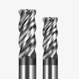
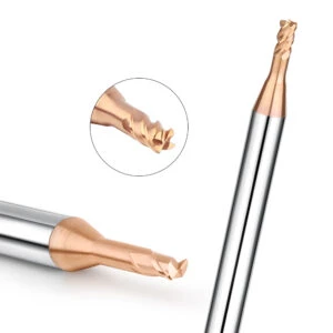
As a dedicated end mill for mold steel manufacturer, we know that fresh tools straight off a 5-axis grinder possess an extremely fragile, as-ground sharp edge. Under hard milling conditions, immense cutting forces concentrate right at the fragile tip. Without precise control over edge rounding or chamfering, this severe stress delaminates the coating almost instantly. This triggers rapid structural chipping of the underlying carbide substrate.
This engineering rule applies to medium-hardness materials like NAK80 or pre-hardened H13 just as much as it does to ultra-hard steels. Micron-level edge honing on a 55hrc end mill for mold steel completely dictates the tool’s final lifespan. This baseline is exceptionally critical when running a ball nose end mill for 3D profiling. Because the cutting velocity drops to near zero at the center tip, an unhoned or asymmetrical edge will rub and extrude rather than cut. This creates severe tool deflection and chatter, leaving nasty witness marks across your mold cavity.
Grinding a razor-sharp edge is simple. However, identifying the microscopic balance point between wear resistance and sharpness for varying cutting loads and materials is a true science. It requires deep engineering knowledge to protect a 65hrc end mill for mold steel under high loads.
If you are constantly tweaking speeds and feeds on the shop floor without resolving tool breakage or poor surface finishes, ask yourself this: Was your production bottleneck actually pre-determined during the very last stage of the tool’s manufacturing process, before it ever left the factory?
Why Standard Sharp Edges Fail on Hardened Mold Steel
If you visit our R&D lab or talk with our field application engineers late at night, you will learn a counter-intuitive rule: in hard milling, the sharper the edge, the faster it dies. CNC programmers transitioning from soft materials to hardened mold steel often make the mistake of blind faith in “sharpness.” They assume sharper tools lower cutting resistance. However, when tackling heat-treated mold steel with dense molecular structures, a razor-sharp edge simply cannot withstand the massive normal forces generated.
During our 16 years of on-site process optimization, we have seen countless tools ruined by this misconception. When an untreated, microscopically serrated sharp edge bites into a hardened block, stress instantly concentrates at the weakest structural points. Rapid heat buildup then causes thermal spalling of the coating, followed by localized chipping of the substrate. This is why, as a specialized end mill for mold steel manufacturer, engineered edge prep on every tool is our mandatory standard to ensure survival on your shop floor.
The Brutal Reality of Chipping with a Sharp 55HRC End Mill for Mold Steel
When machining pre-hardened or hot-work die steels like NAK80 or H13, many programmers select razor-sharp flutes to chase a pristine surface finish at high RPMs. Unfortunately, this strategy often leads directly to a dead end. Just last month, a client milling appliance mold cavities complained that their standard 4-flute flat end mills developed visible, jagged chips along the peripheral edges before completing even half of a roughing pass, marring the workpiece with heavy chatter marks.
At a hardness of around 55 HRC, cutting forces rarely snap a solid carbide tool body outright, but they destroy untreated sharp edges via micro-fatigue. Under the dual assault of extreme mechanical friction and intermittent thermal shock, an unfortified tool tip is as fragile as thin ice. Without utilizing a precise micron-level honing process to build a stable support zone, a 55hrc end mill for mold steel cannot balance impact resistance with sharpness, resulting in endless downtime.
Micro-Chipping vs. Macro-Fracture: Real Cases from Our European Automotive Mold Customers
Through long-term technical partnerships with major European automotive mold shops, we helped their process directors classify two distinct failure modes: micro-chipping and macro-fracture. Often, when operators see a broken tool, they blindly blame a generic “bad batch” and demand harder carbide grades. However, our microscopic analysis of returned tools proves these failures stem from completely different root causes. Macro-fracture comes from instant overloads like poor chip evacuation, while micro-chipping is 100% caused by uneven microscopic stress.
We solved a major bottleneck for a German headlight mold project involving continuous corner-clearing with a ball nose end mill. In tight 3D contours, the tool’s center velocity dropped near zero, meaning the sharp edge could not form proper chips and resorted to heavy material extrusion instead. This high-frequency friction spalled the coating, creating micro-chips that acted as stress concentration points. Once these points cracked, they triggered a total macro-fracture, proving that you must diagnose the micro-edge before changing your entire cutting cycle.
Why We Say “Sharpness is the Enemy” When Machining with a 65HRC End Mill for Mold Steel
When material hardness crosses 60 HRC up to 65 HRC—like quenched SKD11 or induction-hardened tool steels—conventional cutting physics completely transform. At this extreme level, attempting to cleanly “slice” metal is unrealistic; the process relies on localized material shear and yielding under immense pressure. In this punishing environment, pursuing a traditional razor-sharp edge means fighting the laws of physics. That is why we openly tell our fellow engineers that sharpness is the ultimate enemy of hard milling.
To survive, a high-rigidity 65hrc end mill for mold steel requires an engineered negative land (T-land) or a heavy, obtuse-angle hone. While this micro-geometry intentionally increases initial cutting resistance, it drastically expands the cross-sectional area of the cutting edge. This design distributes the massive normal forces evenly backward into the robust carbide substrate. If you approach ultra-hard mold steel with an aluminum-cutting mindset, ruined edges and premature failures will remain a constant shop floor nightmare.
Demystifying the Edge Preparation Methods We Employ as a Manufacturer of End Mills for Mold Steel
Step into our dust-free grinding workshop, and you will see German 5-axis CNC tool grinders running at full capacity. However, as a specialized end mill for mold steel manufacturer, we know that primary relief and rake grinding only get the tool 80% of the way there. The true secret to hours of continuous, chip-free cutting lies in our subsequent microscopic edge reinforcement. Based on your specific steel grades and cutting conditions, we utilize proprietary abrasive media to microscopically modify the tool’s cutting edge.
Under a microscope, a freshly ground “raw” edge appears as an irregular line riddled with micro-serrations and internal tensile stresses. If left untreated, these micro-defects act as immediate failure points when hard milling tough cavity blocks. That is why we use advanced suspended-abrasive grinding and nylon-brush polishing techniques to sculpt the cutting edge. This precise micro-engineering creates the most robust physical foundation for your demanding high-hardness applications.
Rounding vs Chamfering: Which One We Engineer to Stabilize Cutters?
In our engineering database, we constantly balance two primary micro-geometries: honing (edge rounding) and chamfering (negative T-land). Both methods increase the cross-sectional area of the cutting edge, but they serve distinct machining environments. For light-to-medium finishing or when chasing tight surface finishes, we choose a micron-level edge rounding treatment to preserve cutting fluidity. For heavy roughing or interrupted cuts with severe mechanical shock, a negative chamfer provides superior edge rigidity.
This is rarely a binary decision; it depends entirely on the mechanical properties of your workpiece. For example, when configuring a 55hrc end mill for mold steel for die-cast mold applications, we often deploy a hybrid “chamfer-plus-hone” profile. The chamfer redirects intense cutting forces into compressive stresses that the carbide substrate handles with greater resilience. The subsequent micro-hone eliminates sharp intersections, preventing premature coating spallation caused by uneven film thickness along acute angles.
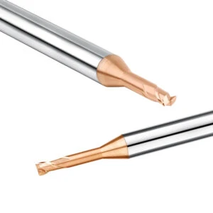
The Micro-Inch Control: How We Calibrate the Perfect K-Factor on a Ball Nose End Mill
Controlling micro-geometry on corner radii is exceptionally complex, especially when finishing deep cavity roots. When grinding a high-precision ball nose end mill, we rigorously monitor a critical parameter: the K-factor (Asymmetry Coefficient). This coefficient defines the ratio of material removed from the rake face versus the clearance face during honing. If this ratio shifts too far to either side, the ball cutter will generate erratic force feedback during 3D contouring.
We solved this exact issue for an automotive client experiencing surface rippling while machining headlight mold cavities. On a ball nose tool, the cutting speed drops linearly from the outer diameter to nearly zero at the center tip. This means different points along the radius experience completely asymmetrical cutting resistance. By calibrating a streamlined, asymmetrical edge profile at the micrometer level, we eliminate the high-frequency squeezing and elastic deformation that ruin mold surface finishes.
Over-Honing vs. Under-Honing: Balancing Cutting Resistance and Edge Strength
Tuning a cutting edge is like walking a tightrope on the shop floor. Under-honing leaves the cutting edge excessively sharp, meaning it lacks the structural mass to protect the coating and substrate from micro-chipping. Conversely, over-honing creates an oversized radius that prevents the tool from cleanly shearing metal. This forces the tool to plow and rub against the workpiece, causing machine spindle loads to skyrocket and inducing heavy chatter.
This balance is vital when using a 65hrc end mill for mold steel for deep-cavity corner finishing on quenched dies. Since cutting zone temperatures frequently exceed 800°C, the friction from an over-honed tool triggers severe thermal fatigue cracks in the carbide. To prevent this, we use high-resolution white-light interferometers to inspect every production batch. We lock the edge radius tolerance within a tight ±2 microns to ensure the perfect balance between cutting resistance and edge strength.
Engineering the Edge: How We Optimize Profiles for Different Hardness Levels
We frequently see workshop supervisors attempting to run a single cutting edge specification across every mold steel grade. However, in real-world hard milling, every 5-point increase in Rockwell hardness completely alters the stress states within the cutting zone. As a qualified end mill for mold steel manufacturer, our core mission is to custom-tailor the cutting edge micro-profile based on the specific mechanical properties of your heat-treated material.
Low-hardness, high-toughness pre-hardened steels generate entirely different shear slip patterns during chip formation than high-hardness, brittle quenched steels. If your tool’s edge radius or negative chamfer isn’t optimized for the final heat-treat hardness, the tool will either instantly snap in hard materials or suffer severe thermal welding in gummy steels. We use your actual cutting depth (ap) and step-over (ae) to adjust our grinding and brushing cycles, optimizing performance at the micron level.
Our Micro-Geometry Protocol for a 55 HRC End Mill for Mold Steel
Pre-hardened steels like NAK80, H13, or 718H typically fall within the 35 to 55 HRC range. During CNC machining, these materials exhibit high toughness, producing long, continuous chips and showing a pronounced tendency toward work hardening. If the cutting edge is over-honed and too blunt, it won’t cleanly shear the metal during interrupted cuts. This increases plastic deformation and causes cutting temperatures to soar, leaving a work-hardened surface layer that makes bench polishing a nightmare.
Consequently, when engineering our 55hrc end mill for mold steel series, we use a highly controlled, moderate edge-rounding protocol. We restrict the average edge radius to between 12 µm and 18 µm, paired with a slightly positive rake angle. This micron-scale hone protects the tool coating from thermal fatigue spalling during entry while keeping the edge sharp enough to slice smoothly. In production, this micro-configuration drastically minimizes tool deflection against side walls, securing your critical dimensional tolerances.
Extreme Edge Toughening Required for a 65 HRC End Mill for Mold Steel
When mold steel is thoroughly quenched past 60 to 65 HRC (like SKD11 or D2), traditional cutting mechanisms fail completely. The abrasive wear inflicted by a hard martensitic matrix is brutally severe, pushing localized cutting zone pressures past several gigapascals. If you attempt to use a standard sharp tool here, the pristine, untreated edges will suffer immediate macro-chipping within the first cutting path. This extreme operating environment demands an aggressive micro-reinforcement strategy.
To ensure our 65hrc end mill for mold steel survives these punishing, high-load environments, we grind a highly rigid negative chamfer profile. We first apply a micro-negative land (T-land) onto the edge, measuring roughly 0.03 mm wide at an angle of -15° to -20°. Immediately after, we superimpose a heavy 25 µm edge hone. This composite geometry acts like a shield, diverting massive shear forces away from the fragile tip and backward into the robust, well-supported carbide core.
The Symmetrical Edge Secrets Behind Our High-Precision Ball Nose End Mill Series
Finishing complex 3D profiles and free-form contours with ball nose cutters introduces intricate geometry variations. While supporting multi-axis machining centers across North America, we found that standard ball nose cutters often leave asymmetrical surface traces—one shallow, one deep—along cavity radii. Operators usually blame spindle runout for this issue. However, high-magnification inspections reveal the real culprit: a subtle asymmetry in the micro-edge rounding on opposing sides of the ball flutes.
The manufacturing secret behind our high-precision ball nose end mill series is ensuring flawless geometric symmetry along the entire spherical radius. Because the cutting velocity continuously decreases toward the central zero-speed zone, we dynamically adjust our brushing angles and duration during polishing. This keeps the K-factor perfectly balanced at a near-absolute 1.0 ratio across the entire cutting profile. This precise symmetry eliminates sudden force spikes during multi-axis simultaneous milling, stopping chatter at the source to deliver a direct mirror finish.
The Direct Impact of Edge Prep on Your Shop’s Bottom Line
When talking with shop owners and financial directors, their primary concern isn’t theory; they want to know how much money micron-level edge prep can save. Many shops dump capital into brand-new machine tools or squeeze raw material vendors while ignoring a silent budget killer: unexpected machine downtime. As a dedicated end mill for mold steel manufacturer, our field data from Western workshops proves that micro-geometric edge enhancements yield economic benefits that translate directly onto your corporate balance sheet.
Without rigorous micro-calibration, tool failure remains completely random and unpredictable. This forces operators to constantly babysit the control panel, watching for spindle load spikes before a catastrophic chip scraps a high-value cavity block. Conversely, establishing an engineered mechanical barrier on the edge prior to shipping dramatically increases tool life predictability. This predictability allows you to confidently run unattended, lights-out night shifts, drastically shortening cycle times and boosting your net profits.
Eliminating the “Break-In” Period for Operators: Consistency Across Every Batch
Every machinist knows the frustration of loading a fresh tool from the exact same batch, only to watch it chip instantly on parameters that the previous tool ran flawlessly. To avoid this, seasoned operators waste ten to fifteen minutes running new tools at heavily reduced feeds and speeds—a cautious ritual known as the “break-in period.” In reality, this waste happens because traditional toolmakers lack a standardized passivation process, leaving erratic, microscopic grinding burrs on the finished flutes.
To eliminate this bottleneck, we subject every single 55hrc end mill for mold steel lot to automated micro-consistency indexing before packaging. Thanks to our standardized edge rounding, the tool enters its most stable cutting state the very second it sparks into the metal. For your programmers, this means machining parameters can be fully standardized. Regardless of the batch number, force feedback and wear patterns remain completely identical, securing the operational stability precision shops require.
Thermal Crack Prevention: How We Reduce Thermal Stress in Dry Cavity Milling
Intermittent roughing in deep mold cavities generates localized friction zones that instantly spike past several hundred degrees Celsius. Most North American shops prefer high-pressure air blast over coolant during dry milling to ensure proper chip evacuation. However, this cross-flow subjects an unreinforced sharp edge to a violent, high-frequency thermal cycle of hot cutting and cold exposure. This rapid expansion and contraction quickly develops micro-thermal cracks perpendicular to the cutting edge.
When inspecting these cracked 65hrc end mill for mold steel samples in our lab, we routinely find these fractures originating at weak micro-serrations before propagating deep into the carbide core. By engineering a precise negative land chamfer paired with cross-smoothing polishing, we redirect destructive thermal stress away from the fragile tip and back into the heavy alloy core. This micro-topography arrests crack propagation, allowing for faster metal removal and safer, extended runtimes.
Achieving the Crucial Mirror Finish in Injection Molds with Properly Honed Tools
Medical and electronics packaging molds tolerate zero surface blemishes, meaning your finished cavities must achieve an exceptional mirror finish. Relying entirely on manual bench hand-polishing destroys production efficiency and risks blowing past tight dimensional tolerances on critical corner radii. The ultimate goal is always to mill a high-gloss finish directly on the CNC. Yet, when operators try this using standard, unconditioned sharp tools, they often end up with a hazy, scratched metal surface.
When supplying high-precision ball nose end mill lots to mold shops, we always remind their team: a flawless finish relies on compressive shearing, not scratching. An unconditioned edge suffers micro-deflections and high-frequency chatter during high-speed contouring, tearing the metal molecules unevenly. Conversely, an ultra-fine suspension-lapped profile acts like a clothes iron at the micron level. It smoothly shears and flattens microscopic surface peaks, eliminating hours of secondary hand-polishing.
How to Troubleshoot Edge Prep Failures on the Shop Floor
Few things are more aggravating than a brand-new tool mystery-failing right in the middle of a tight production run. When the cutting pitch sounds off, the workpiece surface turns matte, or the flutes fracture after only a few passes, process engineers must act fast. Many peers habitually blame bad machine rigidity or assume the manufacturer supplied a sub-optimal carbide grade. However, our field diagnostics show that over 80% of premature wear stems from poor micro-stress distribution along the cutting edge.
Advanced CAM toolpaths and high-hardness coatings are only as good as the cutting edge geometry supporting them. If your edge preparation conflicts with your current spindle dynamics, fixture clamping pressure, or workpiece heat-treat state, you will hit a technical bottleneck. As engineers working the front lines of metal cutting alongside you every day, we suggest stepping away from the control panel during your next tool change. Take a moment to evaluate your current setup against a few practical diagnostic rules.
Is It a Defective Coating or Wrong Edge Preparation? Our Field Diagnostics Checklist
When a tool exhibits extensive surface flaking, supervisors usually assume the coating adhesion is defective. However, if high-magnification inspection shows the spalling is concentrated strictly along the intersection of the cutting edge and rake face—rather than the flat flank—and is accompanied by micro-sawtooth chipping, the coating process isn’t at fault. You are actually looking at a direct micro-geometry mismatch between your tool’s edge radius and the material’s cutting resistance.
True coating delamination peels off in large, sheet-like flakes, exposing perfectly smooth carbide underneath. Conversely, if your tool is under-honed and too sharp, the edge suffers localized mechanical yielding the instant it hits hard metal. This microscopic substrate fracture breaks away, carrying the surface coating along with it. If you are experiencing this on your current batch run, stop looking for a new coating supplier and start evaluating whether your tool’s edge hone is heavy enough.
Adjusting Feeds and Speeds to Match an Engineered End Mill for Mold Steel
Applying rigid, generic speeds and feeds to a highly engineered end mill for mold steel is a recipe for premature failure. Tools featuring specialized micro-geometries operate in sweet spots that differ wildly from standard, sharp-edged cutters. If you run light depths of cut paired with fast table feeds, check your chip morphology. If the chips look like fine, powdery dust and the machine emits a muffled thud, your feed per tooth has fallen below the tool’s hone radius, causing the edge to rub instead of cut.
To fix this, always ensure your depth of cut sits slightly above the edge rounding radius. When milling hardened cavities, back off the surface footage (Vc) to control frictional heat, but boldly increase your chip load (fz). This adjustment forces the cutting edge past its passive micro-zone, allowing the flutes to cleanly shear the material and throw heat out with the chip. Tuning parameters isn’t about running the machine at maximum RPM; it’s about matching the engineered shear angle of the tool.
When to Consult an End Mill for Mold Steel Manufacturer for a Custom Geometry Solution
Catalog tools easily manage standard hard milling jobs, but complex mold designs regularly present extreme scenarios that break conventional rules. If you are struggling with a grueling application—like long-reach slotting inside ultra-deep cavities, clearing corners at an 8:1 length-to-diameter ratio, or tackling interrupted cuts across uneven induction-hardened faces—and standard tool swaps keep snapping every few cycles, you need a custom engineering intervention.
Production bottlenecks are often broken by tailoring the tool directly to the application. If you are stuck facing an unresolvable shop floor issue, consider partnering with a direct end mill for mold steel manufacturer to analyze your exact setup. By examining your specific machine rigidity, workpiece drawings, material grade, and heat-treat data, we can modify core diameters, helix angles, and asymmetric K-factor pr


