


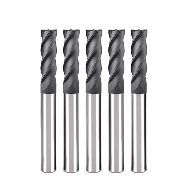
While setting up an automated line for a German automotive supplier processing alumina (Al2O3) substrates, we hit a familiar wall. Seeking faster cycle times, their engineers applied high-hardness steel parameters directly to CVD diamond-coated tooling. Within three minutes, the cutting edges suffered micro-flaking, severe edge chipping ruined the substrates, and the entire batch was scrapped.
Over fifteen years of B2B field support, we have seen this mistake repeatedly: forcing metal-cutting logic onto brittle ceramics.
As a diamond end mill manufacturer supplying precision shops across Europe and North America, we see these daily pain points. Engineers either run overly conservative parameters out of fear, accelerating dry-friction wear, or push speeds too aggressively. This thermal shock instantly destroys premium diamond carbide end mills.
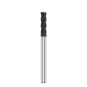
Successfully machining ceramics like zirconia or alumina requires a precise balance: high spindle speeds paired with tiny depths of cut to operate in the “ductile regime.” Whether you use a rigid diamond 4 flutes end mill for side milling or a diamond bullnose end mill to dissipate corner stress, your parameters dictate tool survival.
This guide distills ten thousand hours of shop-floor testing and troubleshooting into actionable rules. If you want to maximize your diamond end mill for ceramic applications or evaluate cost-effective china diamond mills, these field-tested guidelines will save you thousands in scrapped material.
When your diamond coated end mill begins to chatter or chip, the coating itself is rarely at fault. Instead, your feed per tooth is likely pushing the material past its fracture toughness limit.
Shop-Floor Pain Points: Why Speeds and Feeds Often Ruin Tools During Ceramic Machining
Over sixteen years of technical support across Europe and the US, we have identified a clear pattern on the shop floor. Nearly 70% of ceramic machining failures stem from improper speeds and feeds rather than tool defects. Programmers accustomed to metalworking often apply steel or titanium logic to hard ceramics. Consequently, their setup rapidly destroys a high-quality diamond end mill within minutes.
Ceramics lack the thermal conductivity and plastic deformation of conventional metals. When cutting parameters are set incorrectly, massive cutting forces and trapped heat accumulate at the tool edge. Operators frequently blame the tool manufacturer for premature edge chipping. However, a quick review of their CAM parameters usually reveals the true culprit: flawed cutting logic.
The Brittleness Trap of Zirconia and Alumina: Breaking Down Cutting Forces
While assisting a North American medical supplier with zirconia (ZrO2) orthopedic components, we identified a classic failure mode. The customer reported that their diamond end mill chipped immediately upon engagement, assuming the tool lacked rigidity. Using an on-site dynamometer, we measured normal cutting forces that were three times higher than tangential forces. This unbalanced stress distribution caused violent grain spalling.
Both alumina (Al2O3) and zirconia offer high hardness but extremely low fracture toughness. When engineers run an excessive radial depth of cut, the edge crushes the material instead of shearing it cleanly. We always advise clients to monitor normal cutting forces. Once you cross the brittle-to-ductile threshold, catastrophic edge chipping becomes inevitable.
The Cost of Blindly Applying Carbide Parameters to Diamond Tools
A European manufacturer tried boosting material removal rates on ceramic components by applying hardened steel strategies. They lowered the spindle speed and increased the feed per tooth to reduce heat. However, diamond oxidizes in air above 600°C–700°C. The resulting friction caused extreme thermal expansion mismatches between the diamond coating and the carbide substrate, peeling the coating right off.
Carbide substrates and diamond films react very differently to thermal stress. When cutting temperatures spike without proper dissipation, severe interfacial shear stress develops. We remind machinists that blindly lowering spindle speed while increasing depth of cut will not protect the tool. Instead, severe thermal stress will instantly ruin an expensive diamond-coated tool.
Forced Crushing vs. Micro-Cutting: How Speed and Feed Dictate Micro-Fractures
Precision ceramic machining relies on operating below the material’s critical depth of cut. When feed per tooth (IPT) stays within a precise, micron-level range, ceramics exhibit ductile-regime machining. However, if the feed rate slightly exceeds this threshold, the removal mode shifts to brittle fracture. During shop tests, we saw operators drop feed rates too low to reduce noise, causing severe friction that accelerated wear.
Balancing cutting speed (SFM) with feed per tooth regulates friction heat, chip evacuation, and micro-fractures. Aggressive feed rates send deep micro-cracks into the workpiece. Conversely, ultra-low feeds cause the tool edge to rub flat almost instantly. The best approach is increasing surface speed to soften the cutting zone while maintaining a light feed rate.
Practical Parameter Chart: Recommended Parameters for Ceramic End Mills
Through years of establishing cutting databases for global manufacturers, we found one absolute rule: universal ceramic parameters do not exist. Parameter charts from suppliers often reflect ideal laboratory environments. Once introduced to real-world CNC setups with minor spindle runout (exceeding 0.003 mm), real tool life drops significantly. Machinists need practical guidelines that boost material removal without shattering the tool.
We always separate parameters for roughing and finishing operations because the physical loads differ entirely. Beyond basic spindle speed (RPM) and feed rate (FPM), successful setups require managing axial depth of cut (ADOC) and dynamic toolpaths. Mastering these variables ensures safe, predictable ceramic machining across different engineering ceramics.
Roughing Parameters: Balancing Material Removal Rates with Substrate Protection
The main challenge in roughing ceramics is maximizing volumetric removal without breaking the carbide shank under heavy impact. While optimizing silicon nitride (Si3N4) valve cores for a German industrial client, traditional heavy cuts generated massive normal forces. These forces penetrated the coating and snapped the carbide base. We resolved this by implementing high-speed trochoidal milling with small radial engagement.
For roughing, maintain surface speeds between 120–180 m/min with a feed rate of 0.008–0.015 mm per tooth. Keep the radial depth of cut under 8% to 12% of the tool diameter to minimize contact area. This light-cut strategy directs thermal buildup into the air, preventing thermal shock and micro-cracking inside the carbide substrate.
Finishing Parameter Settings: Eliminating Micro-Chipping via High Speeds and Micro-Feeds
During finishing operations, your primary goals are achieving smooth surface finishes (Ra ≤ 0.2 μm) and eliminating edge chipping. While machining alumina substrates for a Swiss instrument maker, dropping the feed rate below 0.003 mm per tooth successfully shifted the removal mechanism into ductile-regime machining. High spindle speeds generate localized thermal softening, producing a clean, mirror-like surface.
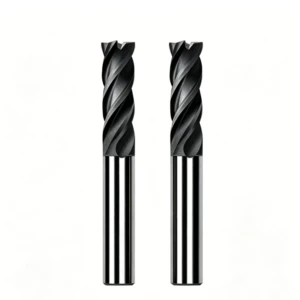
We recommend surface speeds between 200–300 m/min with spindle speeds from 20,000 to 40,000 RPM, depending on tool size. Using rigid 4-flute diamond end mill designs offers distinct advantages, allowing practical table speeds alongside tiny feed rates. Always keep your radial depth of cut between 0.02–0.05 mm to prevent grain pull-out along workpiece edges.
Speed and Feed Rules for Corners, Ramping, and Plunging Operations
Our field records show that over 60% of ceramic tool failures happen during directional changes or plunge moves. As an end mill enters an internal corner, tool engagement increases dramatically, causing cutting forces to spike. Similarly, helical entry places immense axial loads on the bottom cutting edge. Maintaining straight-line feed rates through these features guarantees premature tool failure.
We strongly urge programmers to embed dynamic feed compensation into their CAM routines. Reduce feed rates to 30%–50% of your baseline speed when machining internal arcs. For helical ramping (1°–3° angle), drop the feed rate to 20%–30% while maintaining high air blast pressure to clear fine ceramic dust from the cut path.
Tool Geometry and Parameters: Diamond 4-Flute End Mill vs Bullnose
At facilities across Europe and the US, we often see operators use the same tool geometry for every operation. Using a square-end cutter for complex surfaces or forcing a 2-flute tool to finish deep walls leads to low efficiency and unpredictable tool life. Often, poor performance is not caused by miscalculated speeds and feeds, but by ignoring how tool geometry governs cutting force distribution and chip clearance.
Selecting the right tool geometry establishes the ideal mechanical load distribution for hard ceramic machining. Whether using a 4-flute design for fine surface finishes or a bullnose cutter to protect fragile edges, the tool structure dictates achievable feed rates and depths of cut. Reconfiguring a shop’s tooling setup based on part geometry is always our first step toward stabilizing cutting parameters.
Chip Clearance vs. Rigidity: When to Use a Diamond 4-Flute End Mill
While assisting a UK aerospace supplier with titanium oxide/aluminum oxide composites, we found they were using 2-flute cutters for side milling to prevent clogging. However, the thinner core of the 2-flute tools caused severe deflection, chatter, and poor surface finishes. Introducing a diamond 4-flute end mill increased core rigidity, eliminated chatter, and allowed an 80% boost in feed rates.
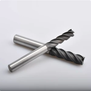
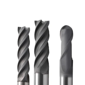
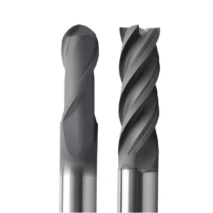
A diamond 4-flute end mill excels in side milling and finishing operations requiring light cuts and fast feed rates. At a constant spindle speed, more flutes allow higher table feeds while maintaining a tiny feed per tooth. However, in deep slotting where chip evacuation is restricted, narrow flutes can pack with ceramic dust. In tight spaces, an aggressive 4-flute tool may increase the risk of edge chipping.
Preventing Edge Chipping on Curved Surfaces with Diamond Bullnose Tools
During 3D surface machining, the fragile 90-degree corner of a flat-bottom tool is often the first point to suffer micro-chipping. High-speed video during a medical component trial showed sharp tool corners concentrating normal cutting forces at a single point. This localized stress quickly caused diamond coating delamination along non-planar toolpaths.
Switching to a diamond bullnose end mill resolved the stress concentration issues. The corner radius distributes cutting forces evenly along the arc, protecting the delicate diamond coating from high impact loads. We recommend using bullnose cutters for 3D contouring and helical cleanup to achieve smooth surface transitions while extending tool life.
Shallow Axial Cuts and High Speeds: Extending Diamond End Mill Life
Many engineers apply metalworking strategies that combine a large axial depth of cut (ADOC) with a small radial engagement. On hard engineering ceramics, this approach subjects the side cutting edges to rapid wear and coating failure. During testing in Germany, reducing the ADOC to 3%–5% of the tool diameter while increasing surface speed by 30% boosted total material removal rates while slowing edge wear.
This shallow-cut, high-speed strategy maximizes the structural rigidity and wear resistance of high-quality diamond end mills. A minimal axial depth shifts primary cutting forces from lateral bending to axial compression, leveraging the spindle’s highest rigidity zone. Trading heavier cuts for higher cutting frequencies reduces micro-fractures in hard ceramics while keeping localized thermal stress manageable.
Cooling and Chip Management: Maximize Tool Life via Parameter Optimization
Speeds and feeds dictate how fast a tool cuts, but cooling strategies determine how long it survives. When machining dense engineering ceramics, improper coolant application often causes thermal shock, ruining premium tools in minutes. If transient cutting temperatures are not controlled scientifically, even perfectly calculated parameters cannot save the tool edge.
Unlike metal swarf, fine ceramic dust is highly abrasive and acts like grinding compound when recut. Coolant systems must provide high-pressure flushing to purge microscopic dust from the cut zone alongside temperature control. Synchronizing coolant pressure, delivery angle, and flow rates with your CAM path is essential to unlocking the full potential of a diamond end mill.
High-Pressure Coolant vs. Mist Cooling: Field Lessons on Thermal Shock
A Swiss manufacturer machining zirconia components suffered severe cracking while using traditional flood coolant. Fluctuating liquid streams splashed onto the hot cutting zone, causing rapid thermal cycling between the diamond film and the carbide substrate. This interface stress caused widespread coating flaking. Upgrading to a continuous 70-bar through-tool coolant system eliminated thermal shock and flushed abrasive dust away instantly.
When through-spindle coolant is unavailable, targeted Minimum Quantity Lubrication (MQL) with high-pressure air-oil mist is an effective alternative. The key to successful mist cooling is absolute flow continuity, as micro-droplets remove heat steadily without drastic thermal cycling. Unstable flood cooling is far more damaging than consistent air mist, which ensures a smooth thermal profile during high-speed ceramic machining.
Dry Machining Strategy: Balancing Dust Extraction and Thermal Cracking
Machining moisture-sensitive materials like aluminum nitride requires dry cutting strategies to prevent contamination. During a German semiconductor project, we implemented high-pressure air blasts to cool the cut zone. The main challenges of dry processing are rapid thermal buildup and abrasive airborne dust, both of which accelerate tool wear if handled incorrectly.
For dry operations, position high-pressure air nozzles precisely at the cutting interface using at least 6 to 8 bar of pressure. This creates an air curtain that forces ceramic dust directly into the vacuum extraction hood. To prevent extreme heat buildup from destroying the diamond-coated end mill, reduce surface speeds and use shallower axial cuts to preserve tool integrity.
Toolpath Optimization: How Helical Ramping Doubles End Mill Lifespan
The geometric path a tool takes when entering material dictates mechanical impact and heat generation. Programmers frequently command tools to plunge straight down into hard ceramic workpieces. These vertical impacts produce massive compressive loads on the bottom cutting edge, causing micro-chipping within just a few cycles.
We mandate using a shallow helical ramp (1°–3°) or a tangential arc entry for all ceramic machining routines. Arc-entry paths increase tool engagement gradually, creating a essential thermal and mechanical buffer for the tool coating. Combining smooth ramp entries with a 50% feed rate reduction during initial engagement prevents force spikes, doubling the service life of your diamond end mill.
On-Site Troubleshooting: Adjusting Parameters Based on Failure Symptoms
Sixteen years of frontline CNC support taught us that even perfect formulas encounter shop-floor anomalies. When machine rigidity varies, fixture clamping shifts, or raw material hardness fluctuates, quick troubleshooting saves entire batches. Operators often replace damaged tools immediately, only to see the new tool fail within minutes, driving up procurement costs unnecessarily.
Mastering parameter fine-tuning is an essential skill for top CNC engineers. When observing workpiece micro-chipping, unusual cutting sounds, or severe wear, avoid rushing to swap tools or blaming raw materials. Inspecting failure modes helps you analyze cutting forces and heat distribution. Targeted adjustments to speeds and feeds often restore your tool to efficient, stable performance.
Extensive Edge Chipping: Excessive Feed or Insufficient Surface Speed?
While assisting a North American automotive supplier with alumina ceramic substrates, we solved a severe edge-chipping issue. On-site technicians assumed high surface speeds were shattering the material, so they lowered spindle speeds, which made chipping worse. Microscopic inspection at the tool exit point revealed brittle fracture propagation, proving the tool was forcibly crushing the ceramic under excessive normal pressure.
Edge chipping occurs when feed per tooth (IPT) exceeds the material’s critical ductile-to-brittle threshold, or when low surface speeds fail to generate localized thermal softening. Rather than dropping cutting speed, lower the feed per tooth by 30%–50% to reduce chip thickness. Simultaneously, increase spindle speeds to leverage high-speed thermal softening and prevent workpiece edge breakouts.
Abnormal Diamond Coating Flaking: Managing Heat Accumulation and Depth of Cut
While troubleshooting zirconia component production for a European valve manufacturer, we observed erratic tool life. Sometimes tools finished dozens of parts; other times, diamond coatings flaked off after processing just a few pieces. Microscopic analysis showed intact carbide substrates but extensive interfacial coating delamination near the cutting edge, pointing directly to excessive localized thermal stress.
Widespread coating flaking signals extreme friction heat or a radial depth of cut (RDOC) that exceeds the interface load capacity. We recommend reducing the RDOC by 20%–30% to decrease engagement angles and frictional contact areas. Pairing this with high-pressure internal coolant or targeted air blasts dissipates heat rapidly, protecting your diamond-coated end mill from thermal stress failure.
Severe Tool Vibration: Spindle Speed Harmonization for Ceramic Tools
Chatter is the silent killer during precision ceramic machining. During a German project involving deep-cavity silicon nitride components, severe high-frequency shrieking marred part surface finishes and caused rapid tool chipping. Brittle ceramics are extremely vulnerable to impact; even minor mechanical resonance creates intense force spikes that shatter super-hard cutting edges.
Simply dropping feed rates rarely eliminates chatter; the most effective solution is spindle speed harmonization. Varying spindle speed dynamically by 5%–10% disrupts cutting force harmonics, breaking the physical feedback loop driving resonance. Upgrading to a rigid diamond-coated carbide end mill, minimizing tool overhang, and using thermal shrink-fit holders fundamentally eliminates vibration.
Procurement and Supply Chain Realities: Evaluating Overseas Diamond End Mills
Hosting hundreds of European and American manufacturing clients over fifteen years revealed a common initial question: “Can your tools match top-tier European service life?” However, once engineers conduct on-machine testing, their focus shifts rapidly from initial purchase price to total cost per part and batch consistency. Pragmatic global supply chains judge tooling quality on real-world shop-floor performance.
The true value of a diamond end mill for ceramics goes beyond nominal hardness numbers. It depends on maintaining stable cutting forces and edge integrity during prolonged, continuous production on abrasive engineering ceramics. Relying solely on low procurement costs while ignoring geometry matching leads to higher total expenses through frequent tool changes and scrapped parts.
Looking Beyond Price: Critical Details During Diamond Tool Testing
When assisting overseas clients with sample testing, factories often judge diamond tools strictly on initial surface roughness (Ra) while ignoring carbide grain size and CVD coating adhesion. High-performance ceramic tools require ultra-fine carbide substrates with exceptional transverse rupture strength. Furthermore, substrates must undergo thorough cobalt etching before coating to ensure robust chemical and mechanical bonding.
If initial tool testing shows promising results but suffers sudden, large-scale delamination after a few parts, inspect the flank face carefully. This failure mode typically stems from weak substrate-to-coating adhesion rather than excessive cutting speed (SFM). Always request verified data on coating thickness uniformity and substrate preparation before finalizing tooling supplier choices.
From Sample Testing to Mass Production: Custom Specifications and Quality Control
As a diamond end mill manufacturer serving high-precision industries globally, we know sample success differs greatly from stable mass production. Clients often place bulk production orders based on great sample results, only to encounter shank breakage or corner chipping later. These issues occur because off-the-shelf standard tools struggle with variations in machine rigidity, spindle runout, and dynamic CAM toolpaths.
When machining complex ceramic components, deep cavities, or thin walls, standard tools may struggle to deliver required material removal rates. Partnering directly with the manufacturer allows custom optimization of non-standard geometries. Micro-adjusting core thickness ratios, flute curvature, edge-honing chamfers, and corner radii for your specific equipment ensures high-volume consistency and optimal tool life.
Factory Cost-Reduction Strategies: Cutting Per-Piece Machining Costs by 40%
True manufacturing cost reduction does not come from buying cheap cutting tools. Instead, it relies on combining optimized cutting parameters, high-value tooling, and smart CAM process paths. Matching spindle speeds and micro-feeds to the material’s ductile cutting regime while implementing dynamic trochoidal milling dramatically extends tool lifespan and reduces downtime.
If you are experiencing low machining efficiency or frequent edge chipping at exit points, analyzing your parameter database is the fastest path to improvement. Gathering your specific cutting conditions, workpiece materials, and CAM toolpath files allows for precise force analysis and geometry matching. Applying these proven strategies will help optimize your shop-floor parameters and lower total manufacturing costs.






