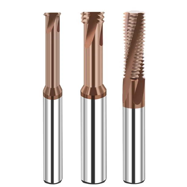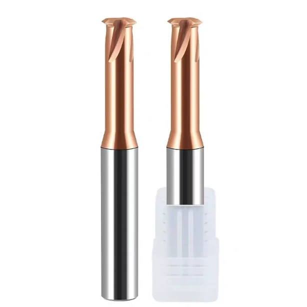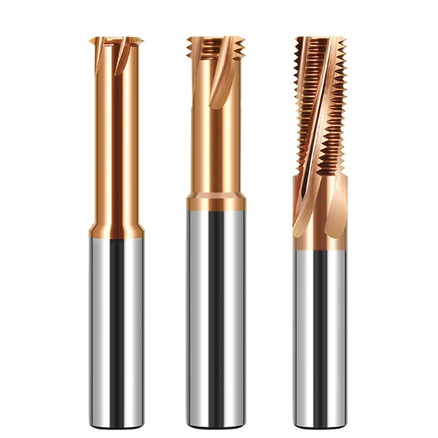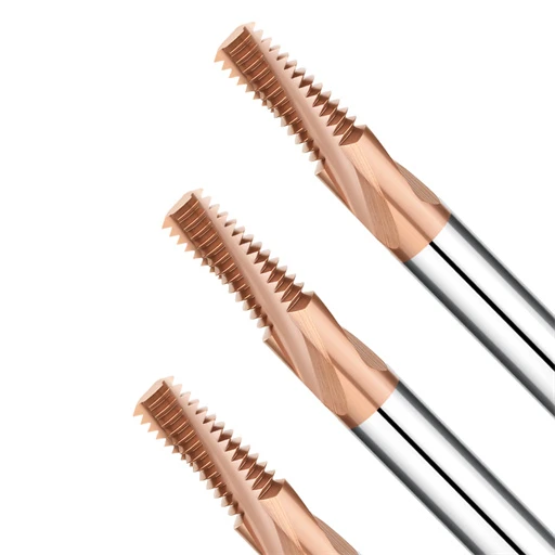

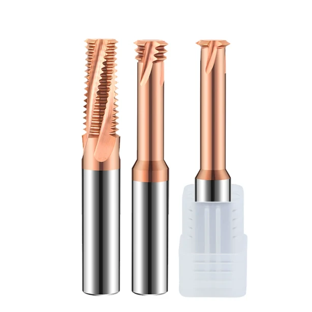
A North American client specializing in injection mold inserts sent us PM-HSS workpieces heat-treated to HRC 63–65. While milling M6×1.0 internal threads on a horizontal machining center, they tested three different cutters marketed for hardened steels. None could reliably finish even four holes: the tips chipped on entry, or flank wear spiked so fast that the parts failed the go/no-go gauge by hole two.
We see this scenario regularly in our technical support records. When a shop hits a wall tapping steel above HRC 60, the usual reaction is to hunt for a harder grade or a miracle coating. But tool analysis shows that a drop in HRC65 thread mill tool life is rarely just a coating issue. Under heavy cutting resistance, microscopic cratering quickly turns into severe thread mill wear and edge chipping.
Hardened steel shows almost zero elastic deflection. Cutting heat concentrates right at the micron-scale contact zone on the tool tip. If the radial step-over is off by a few microns, tangential forces spike past the carbide’s transverse rupture strength. That is why threadmills cannot be judged without factoring in chip evacuation, dynamic runout, and the programmed tool path. Optimizing thread mill durability starts with understanding how thermal stress and impact forces degrade the edge. Are your cutters slicing through the material right now, or are they getting crushed by it?
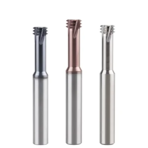
Thread Milling in HRC62–HRC65 Hardened Steel: Why Do Thread Mills Wear Out So Quickly?
Once workpiece hardness surpasses HRC 60, conventional cutting physics no longer applies. Plastic deformation in the shear zone practically disappears. Instead, each tooth engages in a violent, high-frequency cycle of micro-fracturing and intense contact friction. Under these conditions, radial cutting forces on threadmills spike dramatically, meaning even trace runout triggers severe edge degradation.
The confined space inside the thread profile compounds the challenge. Threading tools run with small core diameters and limited flute clearance, while powdery chips fail to evacuate cutting heat. Operators often slow feed rates out of caution, inadvertently rubbing the work-hardened surface. This rapid thermal buildup quickly overpowers the coating, causing aggressive thread mill wear.
Real-World Benchmarks for Thread Mill Tool Life at HRC65: Insights from European and North American Workshops
Machinists often ask us what realistic tool output looks like at HRC 65. Tool catalogs may claim hundreds of holes, but shop-floor data from aerospace and mold shops tells a different story. In materials like hardened D2 or PM steels, a dependable benchmark for HRC65 thread mill tool life is 15 to 30 clean, in-spec blind holes per cutter.
We always advise programming tool changes around process stability rather than pushing for the edge of failure. Hardened materials do not offer a wide, gradual wear window. A thread that feels slightly snug on the plug gage is often followed by catastrophic fracture in the very next hole. Planned tool changes protect the workpiece and yield far lower net costs.
Physical Damage Mechanisms at the Cutting Edge: High Hardness and Elevated Temperatures in Thread Milling
At the microscopic interface, dense alloy carbides inside HRC62 hardened steel act like grinding grit against the cutting relief. During high-speed helical interpolation, each tooth endures thermal cycling between 800°C shock entry and rapid air cooling every few milliseconds. This extreme thermo-mechanical fatigue destabilizes the cutting edge almost immediately.
When localized temperatures peak, the cobalt binder matrix softens, degrading the bond line between the coating and carbide substrate. Deprived of solid binder support, tungsten grains rip free under intermittent shear loads. This initial micro-abrasion quickly evolves into micro-cracking and eventual thread mill edge chipping, destroying thread form geometry.
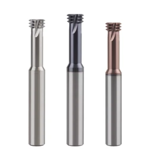
Two Fatal Modes of Thread Mill Wear: Micro-abrasion and Edge Chipping
When inspecting spent cutters under a shop-floor toolmaker microscope, machinists often chalk up failure to general dullness. In hardened steel, however, tool demise follows two very distinct paths. One is steady abrasive erosion along the pitch line. The other is abrupt micro-fracture or violent teeth breakdown. Pinpointing which mechanism dominates is the first step to doubling thread output per cutter.
Confusing these two failure modes leads to costly misdiagnoses. Progressive flank wear offers a measurable inspection window through pitch diameter tracking. In contrast, brittle fracturing strikes instantly when entry shock spikes or chip evacuation stalls. Distinguishing progressive attrition from sudden fracture is essential to diagnosing thread mill wear before catastrophic failure occurs.
The Gradual Erosion of Thread Mill Durability via Flank Wear
In a rigid setup, a uniform wear land on the tooth relief is the natural degradation path. Hard alloy carbides continually scrub the tooth profile, stripping away the outer barrier coat. Rather than monitoring spindle load needles, we track this wear by measuring pitch diameter drift with precision plug gages. Once flank land width exceeds allowable limits, radial forces compound exponentially.
This progressive flattening directly degrades overall thread mill durability. As tooth clearance wears away, the tool stops cutting cleanly and begins burnishing the workpiece. The intense friction causes severe localized work-hardening and adhesive galling. Pushing a worn cutter past this point triggers a rapid thermal spike, turning gradual wear into sudden tool seizure.
Causes and On-Site Troubleshooting of Thread Mill Edge Chipping: Chip Evacuation Interference and Impact Loads
Micro-fracture along the cutting edge is an immediate red flag on the shop floor. In blind holes, powdery hardened chips pack into small flute spaces. The orbiting tool then pinches these trapped particles against the hole wall, causing massive cutting force spikes. This instantaneous bending stress exceeds the core carbide strength, causing rapid thread mill edge chipping.
When chipping strikes, pause the machine and inspect the fracture pattern. Rake spalling points to harsh climb-cut engagement, while rear damage indicates interference during tool retract. Always verify the programmed entry arc: straight linear moves slam the cutting edge into the wall. Furthermore, verify your high-pressure air blast reaches the hole bottom to blow chips clear of the cutting path.
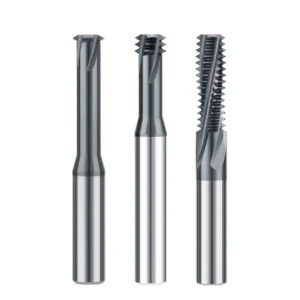
Material and Coating Compatibility: The Foundational Logic Behind Tool Life for Thread Milling Hardened Steel
Many tool buyers simply look at catalog hardness ratings, assuming harder grades always cut hardened steel better. In our manufacturing and regrinding cells, we evaluate interface dynamics between the substrate and the PVD film first. Thread milling creates rapid, high-frequency impact cycles. If the tool substrate lacks vibration-dampening capability, brittle surface films will spall within initial revolutions.
We engineer tools by balancing transverse rupture strength against hot micro-hardness. Trying to force an overly brittle cutter through HRC 60+ steel is counterproductive. Without adequate thermal fatigue resistance in the core carbide, even advanced coatings fail prematurely. Dialing in this metallurgical foundation is how we consistently maximize hardened steel thread mill tool life.
Balancing Impact Toughness and Wear Resistance in Sub-micron Carbide
Rod selection centers on tuning tungsten grain size against cobalt percentage. While ultrafine grains yield high hardness, pushing grain size down without adequate cobalt drops fracture toughness to dangerous levels. In mold slides with slight tool deflection, hard but brittle grades snap quickly under radial bounce.
We rely on dedicated sub-micron carbide substrates with 0.4 to 0.6 µm grain sizes and 10% to 12% cobalt. This specific blend trades minimal nominal hardness for transverse rupture strength above 4000 MPa. The added elasticity cushions the cutting teeth upon initial contact, providing the fracture resistance needed to prevent mass breakage across high-volume runs.
Performance of High-Temperature, Oxidation-Resistant Coatings in Threading Operations on HRC65 Materials
Coating selection requires balancing high hot-hardness with excellent film adhesion. Conventional high-aluminum AlTiN coatings generate protective aluminum oxide scales, but they can be brittle. Under continuous cuts in tight blind holes, thermal stress can cause standard AlTiN layers to shear off tooth rake faces.
We utilize advanced AlCrN architectures with tuned gradient layers for extreme conditions. Chromium-aluminum films withstand thermal peaks up to 1100°C while maintaining balanced residual compressive stress. When running high-load HRC65 threading cutting, this coating barrier blocks cutting heat from reaching the carbide core, suppressing thermal micro-cracks before they spread.
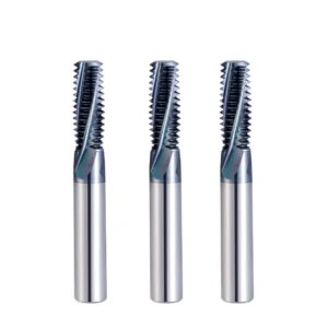
Toolpath Strategy and Thread Mill Tool Life Optimization: Our Feed Optimization Solutions for Machine Shops
Many machinists carry over standard programming from pre-hardened stock, assuming a single helical pass can cut threads in hardened steel. On-site trials show that above 60 HRC, toolpath dynamics dictate whether a cutter survives. Even on high-end machining centers with fast look-ahead, an unbuffered cut creates severe shock loads. Those cyclic impacts destroy premium solid-carbide tools within seconds.
Our field strategy shifts the focus from raw cycle time to managing cutter engagement angle and unit cutting pressure. Thread milling relies on 3D helical planetary motion, where radial contact area changes rapidly with depth. Restructuring the interpolation arc and feed distribution delivers immediate thread mill tool life optimization without purchasing new machine hardware.
The Role of Radial Pass Distribution in Reducing Cutting Loads on Tools Used for Hardened Steel
Taking full thread profile depth in a single pass is a fatal error in hard milling. Engaging the crest and both flank angles simultaneously spikes radial cutting pressure. Slender tool shanks deflect under that load, producing tapered pitch diameters or snapped teeth. We advise shops to split the radial cut into two to three distinct passes when cutting hardened steel.
Crucially, never divide radial depths into equal increments. Equal steps actually increase the arc of contact as the thread form deepens, raising mechanical stress per pass. We program a decreasing depth sequence: an aggressive first pass to remove bulk stock, a secondary pass to size the pitch diameter, and a light spring pass. This distributes mechanical loads evenly across every tooth.
Eliminating Initial Impact via Arc In/Out and Climb Milling
Cutter inspection frequently traces entry-point fractures to linear lead-ins. Straight G01 plunges spike chip thickness instantly from zero to maximum, creating a micro-forging shock that shatters brittle carbide. We enforce a 90° or 180° tangential arc entry. This geometry ramps chip thickness up gradually from true zero, eliminating the primary cause of entry chipping.
Spindle rotation and helical interpolation must always remain locked in climb-milling mode. Conventional milling forces the edge to rub and burnish before penetrating, work-hardening the wall and overheating tool flanks. Combining a tangential roll-in arc with climb milling guarantees clean shearing upon initial contact, preventing thread mill edge chipping before the tool establishes its cut.
The Critical Window for Feed per Tooth: Avoiding Frictional Rubbing and Overload Failure
Machinists often drop the feed rate too low, assuming slower feeds protect fragile cutters. In reality, every honed carbide edge has a microscopic corner preparation radius. If the programmed chip thickness falls below this honing threshold, the tooth cannot shear chips. It simply burnishes the bore wall, generating extreme frictional heat that wipes out flank clearance.
Keep the effective feed per tooth locked inside a strict safe window, typically between 0.0006″ and 0.0014″ (0.015 to 0.035 mm). Feeding below this range accelerates rubbing; feeding above it exceeds the carbide’s transverse rupture strength. Remember to calculate tool-center feed compensation for internal circles, ensuring the peripheral cutting speed stays within safe limits.
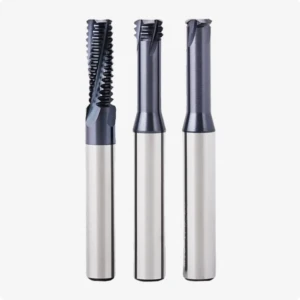
The Practical Impact of Clamping Rigidity and Cooling Strategies on Thread Mill Durability
Programmers frequently dial in feed rates and grade selections, only to compromise the setup with worn collets or standard flood lines. At HRC 65, machining leaves zero margin for mechanical runout or thermal shock. Tool deflection directly degrades thread form quality. Addressing holder rigidity and air delivery is essential to protect thread mill durability.
Extra gauge length or deflected coolant alters stress at the cutting edge. Hard threading generates extreme localized heat alongside high radial loads. Without solid clamping and vibration dampening, tool teeth rapidly disintegrate under micro-chatter. Optimizing the entire toolholding and chip evacuation loop forms the final barrier against unexpected tool failure.
The Decisive Role of Tool Runout Control (TIR < 0.003mm) in Extending Tool Life for HRC65 Hard-Milling
If you use standard ER collets for hardened threads, sweep the tool shank and tip with a dial test indicator. In soft steels, 0.0004″ (0.010 mm) of runout causes minor dimensional drift. At HRC 65, where feed per tooth is only 0.0008″, that same runout forces one tooth to take multiple times its share of the chip load.
We mandate cutting tip runout below 0.0001″ (0.003 mm). Premium hydraulic holders, shrink-fit chucks, or precision milling chucks ensure every tooth shares cutting loads equally. If teeth break on only one side of your cutter, check the holder taper for wear. Proper concentricity is the easiest step to boost HRC65 thread mill tool life.
Advantages of MQL and High-Pressure Cold Air in Hard Milling: Preventing Thermal Stress Cracking
If you flood hard threading cuts with standard water-soluble coolant, switch to dry, filtered air or Minimum Quantity Lubrication (MQL). Interrupted milling teeth cycle through rapid thermal shocks when exiting hot cuts into cold water. This thermal cycle triggers micro-fractures (comb cracks) along the carbide edge, causing premature flank spalling.
In blind holes, high-velocity evacuation matters far more than bulk cooling. Powdered chips trapped in the flutes get recut and wedged against the wall, snapping tool teeth instantly. Directing clean, dry shop air at 90 PSI (0.6 MPa) down the hole ejects packed debris while MQL oil droplets provide essential boundary lubrication.
Successful hard-metal threading relies on an interconnected loop: sub-micron substrate selection, tangential lead-ins, decreasing radial passes, rigid toolholding, and dry chip evacuation. If you are struggling with thread scrap on hard mold blocks, feel free to share your part prints, hole depths, and heat-treat data. We can evaluate your exact setup to dial in a dependable machining process.