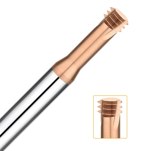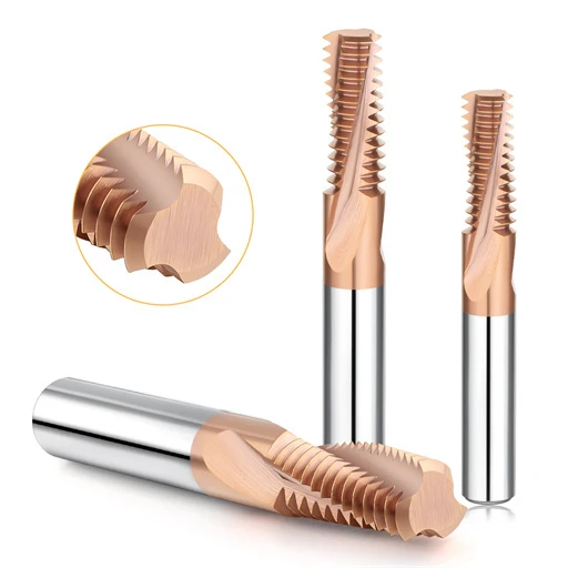

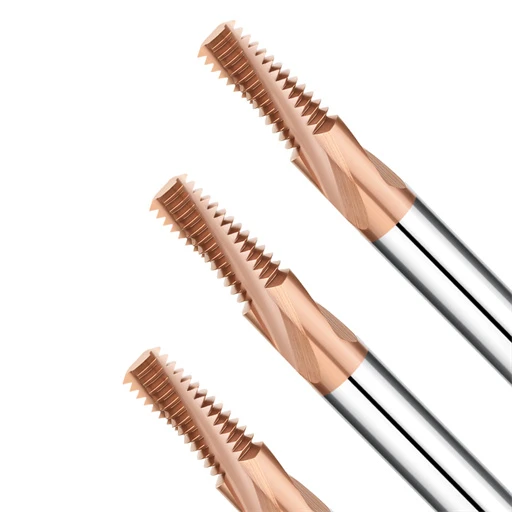
A machining center cutting automotive stamping dies was running D2 tool steel inserts hardened to HRC 58. The spindle speed and feed rate were backed down to 80% of tool catalog specs, and machine rigidity was solid. Yet, by the fourth M6×1.0 blind hole, the operator pulled the tool and spotted micro-fractures along the lead teeth of the solid carbide thread mill. On the fifth hole, the teeth fractured completely.
We have troubleshot this exact breakdown dozens of times across North American and European job shops. Once workpiece hardness tops HRC 50, standard feeds and speeds no longer apply. Through optical and SEM fracture analysis, we consistently find that what machinists report as “premature wear” or “coating failure” is actually mechanical thread mill edge chipping.
When shops face the headache of high hardness mold steel threading, they usually blame brittle carbide grades or over-aggressive cuts. In our engineering practice, the real culprits are different. They stem from excessive thread mill toolholder runout, distorted chip thickness from uncompensated tool-center programming, and severe entry shock from straight-line plunge paths.
Threading fully hardened tool steel is a fine balance between workpiece yield strength and cutter micro-rigidity. If your tools keep fracturing unexpectedly in hardened stock, do you really think switching coatings or blindly cutting your feed in half will fix the root cause?
On-Site Diagnosis of Thread Mill Edge Chipping: Identifying the Root Cause via Failure Morphology
When a tool chips, most operators just hit cycle stop and reach for a fresh cutter. Whenever our application team visits a shop floor, our first step is putting the damaged cutter under a 40x shop microscope. Normal flank wear on HRC 55+ stock leaves a smooth, uniform wear land. In contrast, mechanical fractures leave jagged micro-notches and conchoidal striations that point directly to severe stress spikes.
We urge process engineers to trace the failure back to its origin rather than focusing solely on the final break. When diagnosing repeated tool failure, the fracture surface records the entire cutting history. Learning how to properly diagnose thread mill edge chipping will tell you whether you are dealing with spindle harmonics, entry impact shock, or insufficient toolholding rigidity.
Micro-chipping and Brittle Spalling: Mismatches in Cutting Edge Geometry and Edge Honing
Under magnification, we frequently spot spalling craters concentrated on the primary rake face. This almost always happens when a shop uses general-purpose tooling for hard milling. Operators often assume a dead-sharp tool reduces cutting load. However, a zero-degree or positive rake edge cannot handle the massive shearing resistance of hardened mold steel. The excessive cutting forces concentrate on an ultra-thin edge band, fracturing the coating-substrate bond immediately.
Tool geometry design is a continuous tradeoff between chip clearance and edge backup. When grinding tools for hardened steel, we deliberately engineer the thread mill cutting edge geometry with a distinct negative rake and a 10–15 micron symmetrical or waterfall hone. This slight micro-radius converts tensile loads into compressive stress, effectively protecting the cutting edge from micro-chipping.
Toolholder and System Runout: Why Runout Exceeding 0.005 mm Destroys Teeth on Entry
We always get concerned when we see a customer running a standard ER collet chuck on HRC 60 stock. At that hardness, your planned chip load is often just 0.01 mm to 0.02 mm per tooth. If total radial runout creeps past 0.005 mm, the cutter cannot distribute the cutting forces evenly across all flutes.
The flute pushed outward by high runout ends up carrying 70% to 80% of the entire chip load. This instantly spikes the real-world chip thickness several times beyond design limits. Because quenched steel has near-zero plastic give, excessive thread mill toolholder runout overloads the highest tooth and shatters it on the first revolution, quickly destroying the remaining teeth.
First-Tooth Chipping: Instantaneous Mechanical Shock from Missing Arc-in/Arc-out Moves
When damage concentrates exclusively on the leading engagement tooth while the upper crests remain pristine, the issue is almost always in the CAM code. Many programmers still use straight-line, perpendicular entry vectors into the hole wall. That approach works fine in aluminum or mild carbon steel, but in hardened alloy it slams the tool tip against an unyielding surface like a hammer.
Because hard steel does not deflect to absorb shock, straight-in motion causes chip thickness to spike instantly from zero to maximum. The leading tooth absorbs 100% of that shock load. To prevent sudden first-tooth chipping, our standard programming rule requires a 90-degree or 180-degree smooth tangential arc-in sweep. Cutting the feed by 50% during entry guarantees the tool blends cleanly into the cut without edge trauma.
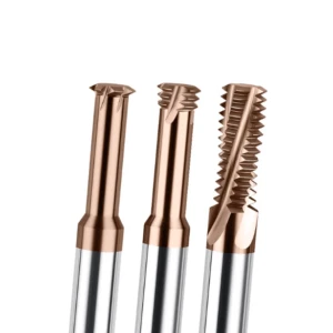
Rigidity Pitfalls and Toolpath Control in High Hardness Mold Steel Threading (D2 / H13 / S7)
Once heat treatment pushes mold steel past HRC 52, standard shop floor rules no longer apply. While soft steels let you power through cuts with raw machine torque, high hardness mold steel threading magnifies every ounce of radial cutting pressure. High material yield strength means even the tiniest flex in the setup translates directly into heavy rubbing between the tool tip and the bore wall.
Many machinists fall into a false sense of security once the spindle and vise are locked down tight. They overlook the slender neck and flute flutes of the cutter itself, which naturally flex under heavy load. If you run standard toolpaths against this hardened resistance without balancing flexural rigidity, chip clearance, and stepovers, subtle micro-vibrations will chew up the crests of your cutting edges long before the tool snaps.
D2 Thread Milling: Selecting Substrate TRS to Counter Secondary-Hardening Carbides
When cutting pre-hardened or annealed steels, shops routinely select ultra-hard submicron carbide substrates to fight abrasive wear. However, when we set up tooling for D2 thread milling, we almost always advise the opposite approach. High-temperature tempering in D2 precipitates coarse, secondary-hardened chromium carbides that act like jagged rocks embedded in concrete, delivering violent micro-impacts to the teeth.
Prioritizing raw substrate hardness over fracture toughness makes tool teeth shatter the instant they slam into these hard carbide clusters. Across hundreds of failure analyses, we consistently spec ultra-fine-grain carbide substrates with a Transverse Rupture Strength (TRS) above 4000 MPa, even if hardness drops slightly to HRA 91. That slight sacrifice in catalog wear resistance gives your tool teeth the elastic compliance needed to survive repeated shocks without chipping.
Blind-Hole Chip Evacuation: Through-Coolant Solid Carbide Thread Mill vs. Air-Blast
When threading deep blind holes in tool steel inserts, poor chip clearance causes far more edge damage than chip-breaking failure. We often see operators aim an external flood coolant nozzle straight at the hole mouth. At high helical RPMs, external fluid never reaches the thread root; instead, it dams up freshly sheared, HRC 60 chips inside the hole, forcing the tool into violent secondary cutting.
To prevent chips from grinding against the cutter, we enforce clear cooling guidelines based on hole size. Below M8, running a through-coolant solid carbide thread mill at 20+ bar provides enough hydrodynamic push to flush heavy chips straight up and out. But on hot-work steels prone to rapid thermal spikes, if fluid pressure cannot clear the bore completely, we switch to dry, high-pressure vortex air to blow chips clear and eliminate thermal shock fatigue.
Radial Multi-Pass Strategy: Eliminating Tool Deflection on Hardened Workpiece Walls
Trying to cut full thread depth in a single pass on hardened steel is a guaranteed way to destroy a cutter. Using laser sensors during cut trials, we consistently see multi-flute tools flex backward under the heavy normal forces of a single pass, especially at length-to-diameter ratios past 3:1. This flex creates tapered threads and triggers an aggressive spring-back bite as the tool sweeps past the entry overlap point.
To stop work-wall deflection from snapping delicate tool tips, we break the operation into three or four radial peeling passes. We never divide the radial depth of cut evenly; instead, we use a decaying stepover where the first pass removes the bulk of the stock. Keeping the final spring pass strictly around 0.02 mm cleans up previous runout waves without generating enough radial force to cause tool deflection.
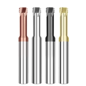
Practical Adjustments for Thread Milling Speeds and Feeds: Hardened Steel Calculations
When cutting edges chip in hard steel, an operator’s first instinct is often to drop the feed override to 50%. In reality, this usually speeds up tooth failure instead of stopping it. Hardened mold steels possess minimal plastic yield, so standard cutting rules fail completely. Operating outside the true plastic shear zone subjects the cutter to destructive, cyclical impact stresses.
Tuning parameters requires managing the relationship between surface footage, chip load, and the helical toolpath center line. Dialing in your thread milling speeds and feeds requires finding the narrow window between two failure modes. Push too hard and mechanical shock shears the tooth face off; feed too lightly and continuous burnishing rubs the edge away, triggering micro-spalling.
Thread Mill Feed Per Tooth (fz): Balancing Friction Rubbing Against Mechanical Overload
During field audits, we regularly catch operators running feeds of just a few microns per tooth to “baby” the cutter. But high-hardness cutters feature an edge hone radius of 10 to 15 microns. If your programmed thread mill feed per tooth is smaller than this hone radius, the edge simply slides across the steel instead of shearing a clean chip. This friction work-hardens the surface instantly, stripping the PVD coating and chipping the edge.
Pushing feed too aggressively causes shear resistance to spike past the compressive yield limit of the carbide. Our shop floor rule is simple: chip load must be at least 1.5 times the edge prep radius to form a real chip, while staying under 70% of the substrate’s yield limit. In HRC 55+ steel, this ideal window sits between 0.015 mm and 0.035 mm per tooth, fine-tuned to your machine’s spindle rigidity.
Machine Surface Speed and Arc Feed Compensation: The Missing Internal Threading Formula
This remains the most common programming mistake we find during customer support calls: programmers using linear milling feed rates for internal helical interpolation. Internal thread milling moves along a concave arc, meaning the tool’s outer edge sweeps a much longer path than its center point. Without adjusting your code, the machine runs the tool center at the programmed speed, causing the actual tooth edge load to skyrocket.
Applying internal feed compensation scales the feed rate down based on the ratio between cutter diameter and hole diameter. Without this math, an innocent-looking 0.02 mm feed per tooth can spike into an actual load of over 0.06 mm at the cutting edge. That hidden overload is why fine-pitch crests frequently snap off during the very first entry pass inside a bore.
Cutting Speed (Vc) Limits: Managing Thermal Cracking in Cemented Carbide Substrates
Machining cold-work steels above HRC 58 converts more than 80% of cutting energy into concentrated heat at the tool edge. If surface speed climbs too high, that heat bleeds directly into the carbide body, regardless of coating quality. When inspecting broken cutters under metallographic imaging, what looks like mechanical edge chipping often turns out to be deep thermal cracking caused by thermal cycling between cuts.
Dropping cutting speed too low is just as risky, as cold workpiece material retains peak shear resistance and batters the cutting edges. We establish a tight surface speed window that keeps the cutting zone hot enough to activate the coating’s oxidation barrier, yet well below the cobalt binder’s softening threshold. Capping surface footage stabilizes the carbide grain structure and keeps edge teeth intact.
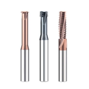
Practical Solutions for Preventing Tool Chipping: Insights from Tool Engineering
When frequent tool chipping halts a machining center, operators almost always want an instant fix. But when you are cutting mold steels above HRC 55, no single adjustment solves the problem alone. We treat the cutter, toolholder assembly, and CNC path as a closed-loop mechanical system. If one link lacks rigidity, every other fix fails.
Drawing on sixteen years of cutter manufacturing and troubleshooting on the shop floor, our goal is systematically breaking the mechanical chain that causes brittle edge failure. We focus on tuning cutting edge loads, upgrading toolholder rigidity, and smoothing interpolation paths. Applying proven fixes for thread mill edge chipping evens out cutting forces throughout the tool’s rotation, pulling the cutting teeth out of high-impact stress loops.
Solid Carbide Thread Mill Optimization: Variable Pitch and Negative Rake Geometries
When mold steel reaches HRC 58 or higher, off-the-shelf general-purpose geometries belong in the scrap bin. In our custom tooling builds, re-engineering the flute layout of the solid carbide thread mill is our primary defense against micro-chipping. Standard cutters with equal flute indexing produce severe harmonic spikes during helical entry, which can shatter delicate tooth crests within seconds.
To kill chatter at the source, we combine unequal flute spacing with variable helix angles to disrupt cyclical cutting force spikes. We also replace fragile positive rakes with a 5° to 8° negative rake and tighten the primary relief. This negative face turns tearing tensile loads into compressive stresses that carbide handles best. Combined with micro-honing, this geometry gives the edge the impact strength needed for hardened steels.
Toolholder Upgrades: Moving Beyond ER Collets to Shrink-Fit and Hydraulic Chucks
During on-site audits, seeing a machinist run hardened steel threads with an ER collet chuck is an immediate red flag. The stacked contact surfaces and slotted spring segments in ER collets flex under heavy lateral cutting pressure. As depth of cut increases, micro-vibrations magnify this deflection until a multi-flute cutter effectively degrades into a single tooth taking the entire beating.
For steels harder than HRC 50, our field standard mandates rigid clamping via shrink-fit holders or high-precision hydraulic chucks. Shrink-fit holders apply 360-degree radial clamping force, holding thread mill toolholder runout below 0.003 mm while offering maximum bending resistance. Hydraulic chucks add internal fluid damping to soak up micro-harmonics. Switching holders alone routinely eliminates more than half of all edge chipping issues.
Climb Milling and Kinematic Checks: Eliminating Micro-Chatter on the Machine Floor
Toolpath kinematics determine whether tooth crests shear cleanly or take a blunt beating. We always verify that operators strictly program climb milling moves. Climb milling lets the tooth enter at maximum chip thickness and thin out smoothly toward exit. Up-milling forces the tooth to rub and burnish against hardened steel before biting, creating frictional heat that rapidly dulls and chips the crests.
Beyond climb milling, servo lag during small-radius circular interpolation can trigger invisible, destructive micro-vibrations. Standard rigid canned cycles often suffer from minor corner hesitation when linking tiny XY arcs to the Z-axis. When thread milling hardened steel, always activate high-precision look-ahead and contour acceleration smoothing in your CNC code. Calibrating axis backlash and tuning servo gain ensures uniform cutting load throughout helical interpolation.