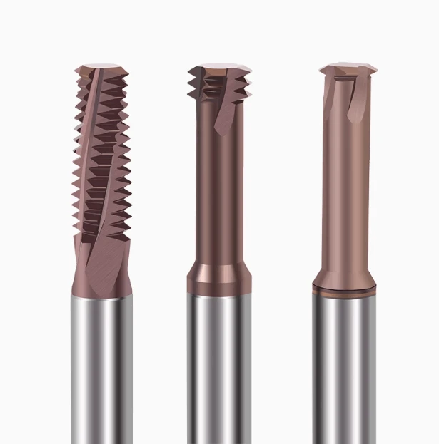
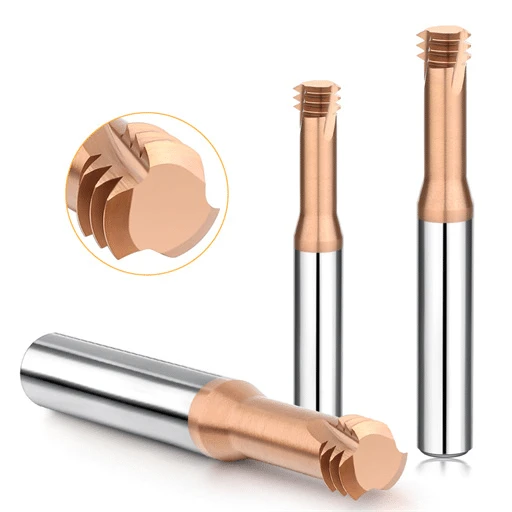
A few months ago, a tool-and-die customer in Stuttgart called us with an urgent problem. They had snapped two solid-carbide tools back-to-back while machining M6×1.0 blind-hole threads into a 1.2379 (AISI D2) mold insert. The insert was vacuum-hardened to 64–65 HRC with only 18 hours left before final delivery. Sinking the threads via EDM was out of the question because the resulting recast layer risked stress cracking during production. Meanwhile, attempting hard milling without dialed-in processes risked scrapping a high-value workpiece with hundreds of machining hours already invested.
We see this exact scenario nearly every month while supporting European and American machine shops. When threading tool steels past 62 HRC, conventional machining logic fails immediately, often chipping the rake face on the very first entry arc. Finding the right thread mill cutting parameters is never as simple as copying speed and feed charts from a catalog. It demands an integrated calculation of tool overhang ratios, effective chip thickness compensation, and high-pressure air blast evacuation.
As a dedicated HRC65 thread mill manufacturer, our role extends beyond grinding carbide; we help shops dial in the dynamic cutting equilibrium of their machine tools. Achieving predictable thread mill tool life in ultra-hard metals requires parameters validated on real machine spindles. Every variable—from the shear-zone thermal softening point to the center-line CNC feed conversion—must be quantified.
When dealing with expensive tooling hardened to 65 HRC, would you rather risk tool breakage by guessing your cut depths, or run a proven set of machining baselines built on real shop-floor trials?
Empirically Validated Baselines: Speed and Feed Settings for Thread Milling HRC65 Hardened and Cold-Work Tool Steels
When cutting 60–65 HRC D2 or CPM 10V, never copy standard alloy steel charts. Cutting resistance here is triple that of pre-hardened steel. The material cannot plastically deform, so chips shear away as tiny, abrasive needles. Establishing accurate HRC65 thread mill speeds and feeds is not about chasing aggressive cycle times; it is about managing heat and stopping micro-chipping so tool life stays predictable.
We anchor cutting parameters to machine rigidity, specifically spindle interface and air delivery. A rigid HSK-A63 or dual-contact BT40 spindle running under 0.002 mm runout can run tighter parameters. If your overhang exceeds 3D in a blind hole, back off the cutting load immediately. Hard milling is always a balance between tool deflection and edge wear, governed by three core variables.
Avoiding the Tool-Breakage Zone—Maintaining Cutting Speed (Vc) within the 25–45 m/min Thermal Wear Boundary
Many machinists instinctively drop spindle RPM the moment they hear tool squeal. In 65 HRC steel, running too slow is fatal. Sub-micron carbide needs controlled friction heat to induce local thermal softening in the shear zone. Below 20 m/min, the steel never softens, forcing the cutting edge to hammer against dead-hard metal. Keeping cutting speed strictly within 25–45 m/min maintains this thermal safety window and preserves your thread cutter tool.
Dial this range to match your coating and air delivery. Premium AlTiN or silicon-doped nano-coatings run happiest around 35–40 m/min under dry air. If your setup relies on low-pressure shop air where chips linger in blind holes, hold surface speed to 25–30 m/min. This prevents heat buildup from oxidizing the coating. Sacrificing a few seconds of cycle time beats overheating the carbide substrate past its yield point.
A Fatal Misconception Regarding Feed per Tooth (fz)—Why Hard Milling Requires 0.008–0.02 mm/z to Prevent Rubbing and Slippage
Programmers terrified of snapping small tools often drop feed to 0.003–0.005 mm/z. This light feed rapidly destroys the tool flank. Hard-milling tools feature a honed negative land or micro-radius of 4–8 μm. If the programmed feed per tooth falls below this hone, the edge cannot bite. It rubs and burns across the surface, creating severe work hardening. Setting thread milling parameters for hardened steel between 0.008 and 0.02 mm/z forces the edge past the rubbing zone into clean shear.
Do not push feed limits blindly. As feed approaches 0.02 mm/z, radial forces climb sharply. On higher length-to-diameter ratios, tool deflection creates a tapered thread pitch diameter that binds your thread gauge. Our standard baseline runs roughing passes at 0.012–0.015 mm/z for a solid bite, dropping to 0.008–0.010 mm/z on the final pass. A clean, positive cut always beats abrasive rubbing.
Radial Feed Strategy: Balancing Cutting Forces Across 2 to 4 Radial Passes
Single-pass threading above 60 HRC is impossible. However, dividing the cut into 6 or 7 tiny passes creates new problems. Ultra-light cuts multiply friction against work-hardened surfaces, causing severe thermal fatigue in the hole. An effective radial pass strategy spreads the cutting load evenly. This controls heat cycles while maintaining pitch diameter accuracy and protecting thread mill tool life.
For thread pitches up to 1.0 mm (M4–M6), a 2- to 3-pass strategy works best. Take 65% of the thread depth on pass one, 30% on pass two, and leave 5% (around 0.02 mm) for a final spring cleanup. For pitches above 1.5 mm, contact area expands dramatically, requiring 4 radial passes to suppress chatter. Proper depth distribution keeps cutting forces stable, prevents edge chipping, and delivers consistent thread gauge fit across the entire batch.
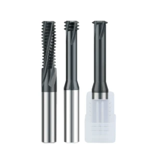
Toolpath Correction and Calculation: CNC Programming Compensation for Thread Milling in Hardened Steel
Machinists often face a frustrating mystery in hard milling. They input recommended speeds and feeds, yet the spindle load spikes immediately or the cutter snaps on revolution one. The root cause is rarely the catalog parameters. Instead, it traces back to geometric errors in CAM toolpaths and uncompensated post-processors. At 65 HRC, material yield strength is immense. Any uncompensated linear path interpolation spikes instantaneous cutting pressure at the tool tip.
Through years of on-site support across US and European shops, we learned that calculating precise thread milling parameters for hardened steel requires building a dynamics-aware toolpath. You must adjust for the true cutting thickness at the hole wall, smooth out high-shock entry points, and counteract shank deflection during long overhangs. Addressing these CNC programming factors stops premature tool failure and eliminates tolerance drift.
Compensating for True Effective Cutting Thickness in Climb Thread Milling: Converting Programmed Tool Center Feed (Vf) to Effective Outer-Diameter Feed
Fanuc and Siemens controls default to reading the feed rate along the tool centerline during helical interpolation (G02/G03). In pre-hardened steels, material ductility forgives the velocity difference between the tool center and outer edge. At 65 HRC, if your tool diameter takes up 70% of the minor diameter, actual chip thickness at the outer edge can double or triple. A programmed 0.01 mm/z can quickly spike to an actual 0.025 mm/z cut, exceeding carbide rupture limits.
To maintain real HRC65 thread milling parameters, we scale the center feed rate via macro programming using this ratio: (Major Thread Diameter – Tool Diameter) / Major Thread Diameter. Applying this scaling factor ensures the cutting edge operates at the actual intended chip load. Material shears cleanly along the intended shear plane, shielding the spindle from dangerous instantaneous torque spikes.
Helical Entry and Exit (Roll-in/Roll-out) Settings: Eliminating Micro-chipping and Tool-mark Ridges at the Hole Entrance
Over 80% of edge chipping in hardened tool steels occurs during initial entry. Programmers frequently rely on straight 90-degree linear moves or tight tangential arcs. At 60+ HRC, that sudden transition from zero load to full engagement acts like a tiny hammer strike. The carbide tip cannot absorb that shock, leaving dwell marks that fail inspection or snapping teeth outright.
We eliminate entry shock with a smooth 180-degree helical roll-in and roll-out path while matching the Z-axis thread pitch. We also throttle the feed rate down by 30% to 50% along the entry arc, ramping back to 100% only after full engagement. This gradual load ramp cuts initial friction, protecting cutting edges and stabilizing thread mill tool life across long production runs.
Stepped Feed Reduction Algorithm for Overhang Ratios Exceeding 2.5D: Cutting Force Distribution from Hole Bottom to Opening
Deep-hole thread milling in hard tool steel remains a tough engineering challenge. When the overhang ratio exceeds 2.5D or 3.5D, tool deflection scales cubically. Running a constant feed rate from bottom to top causes severe issues at the hole floor, where rigidity is lowest and trapped micro-chips cause secondary rubbing. Deflection pinches the minor diameter, causing thread taper.
We resolve deep-hole taper by running a stepped feed algorithm in the CAM post-processor. At the hole bottom, throttle cutting load to 70% of baseline with shallow passes and dry air blast. As the cutter spirals upward toward the rigid hole entrance, step feed smoothly back to 100%. This staged force profile suppresses chatter, reduces cyclic fatigue on the thread mill cutter, and saves high-value molds from late-stage scrap.
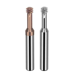
Failure Analysis and Life Management: Assessing Thread Milling Tool Wear and Maximizing Tool Life
Many shops practice reactive maintenance, replacing thread mills only when they snap or fail a Go-gauge check. In 65 HRC tooling steel, this gamble often scraps an entire finished mold block. Microscopic edge wear progresses rapidly from nano-coating loss to catastrophic fracture, leaving a narrow intervention window. A predictive tracking system pinpoints tool changes before expensive accidents happen.
Using Scanning Electron Microscopy (SEM) on worn cutters from mold-making clients, we confirmed that catching early wear indicators eliminates random tool breakage. Managing thread milling tool wear requires tracking early warning signals like slight spindle current jumps, dark chip discoloration, and flank wear band expansion. Acting on these signs locks in thread precision while maximizing cutter output.
Critical Signals for Distinguishing Between Rake Face Micro-chipping and Flank Wear
During shop setups, inspect cutters using an optical microscope at 20x magnification minimum because wear mechanisms on the rake and flank faces differ completely. Irregular notches or micro-fractures on the rake face indicate mechanical shock from violent entry, chip recutting, or machine vibration. A smooth, uniform silver-gray wear band on the flank face indicates standard, healthy abrasive wear.
A flank wear band between 0.08 and 0.12 mm signals our safe proactive retirement window before heat spikes uncontrollably. However, if you spot even a 0.03 mm micro-chip on the rake face, replace the cutter immediately. Chipping ruins the honed edge preparation and focuses stresses onto raw substrate. The very next pass risks snapping the tooth, directly compromising expected thread mill tool life.
Causes of Premature Binding with Thread Gauges (Go/No-Go): Pitch Taper Induced by Micro-Deflection and Compensation Adjustments
A familiar floor issue occurs when the Go-gauge fits the first few threaded holes, but by hole ten, it binds halfway down. Machinists often react by bumping up the radial D-offset. This clears the hole bottom, but overcuts the entrance, causing the No-Go gauge to fail. This error rarely stems from OD wear; it is axial reverse taper caused by cutter deflection under radial pressure.
Fixing taper requires structural strategy rather than arbitrary offset changes. Implement staged axial passes or add a zero-depth spring pass to clean up residual stock left by tool deflection. Partnering with a dedicated HRC65 thread mill manufacturer that grinds tools with short cutting flutes and heavy reinforced necks stops deflection at the source, preventing taper issues in deep blind holes.
Workshop Tool Life Data: Correlations Between Coating Failure, Tip Blackening, and Workpiece Burn
Our tool life trials on 64–65 HRC D2 steel using dry air blast reveal a clear three-stage wear curve on M6 four-flute carbide cutters. Through holes 15 to 20, the tool runs in a steady wear state, holding surface finishes around Ra 0.4–0.6 μm with fine silver-gray chips. Around hole 25, concentrated friction flakes off the outer nano-coating layer, signaling the sweet spot for preventive tool replacement.
Past 30 holes, flank friction spikes rapidly and the cutter tip shows thermal blackening. Chips change from silver-gray to dark purple or black, proving cutting temps topped 900°C. That extreme heat tempers and burns the workpiece thread crests, destroying pitch geometry. Setting baseline tool changes at 75% of maximum life is our gold standard for stabilizing thread mill cutting parameters in production.
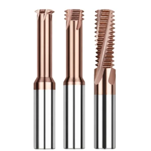
Process Chain Details: Selecting the Right Thread Cutter and Matching Rigid Clamping with Cooling Strategies
When troubleshooting tool breakage across European and US shops, we often see a familiar pattern. Programmers calculate speeds, feeds, and step-downs perfectly, yet the tool screeches or chips immediately upon entering the hole. The culprit is almost always peripheral hardware—excessive collet runout or coolant thermal shock. At 65 HRC, the spindle, holder, cutter body, and evacuation medium form a rigid loop where any weak link spikes cutting forces.
Stable machining and predictable tool life require more than just finding a premium thread cutter tool. You must build a setup with maximum rigidity and minimal thermal stress. Tool runout must stay within a few microns, and your cooling method determines whether the carbide develops thermal micro-cracks. Mastering these hardware details unlocks the true potential of hard milling.
Thread Mill Cutter Selection for 65 HRC Hardened Workpieces: Short-Flute/Long-Neck Design and Ultra-Fine Grain Substrate
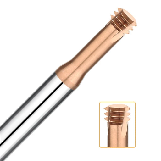
Shops cutting pre-hardened steels often favor full-flute tools covering multiple thread pitches. In 65 HRC tool steel, that choice is disastrous. Cutting resistance scales with contact area; engaging full-flute teeth creates massive radial forces that deflect slender tools, causing immediate chatter. When grinding an ultra-hard thread mill cutter, we use short 2-to-3 tooth flutes with neck relief. This shrinks the radial contact arc and keeps forces near the rigid shank.
Substrate grain size and binder ratios also dictate chipping resistance. Standard tools use sub-micron grains (0.8–1.0 μm), but 65 HRC impacts demand an ultra-fine 0.2–0.4 μm substrate with 8%–10% cobalt. Finer grains dramatically increase hardness and transverse rupture strength. Combined with AlTiN or silicon-based nanocomposite coatings, this structure resists severe abrasive wear and stops premature edge fracture.
Strictly No Wet Machining—Suppressing Thermal Cracking via High-Pressure Air Blast Chip Evacuation
We stop machinists immediately if we see coolant nozzles aimed at a 65 HRC threading operation. Hard milling is an interrupted cut where teeth cycle through extreme heating and cooling. Dry cutting temperatures quickly pass 800°C. Blasting water-based coolant onto glowing carbide triggers intense thermal shock. Within seconds, comb-like thermal cracks form on the flank, leading to spalling and tooth fracture.
The right strategy completely bans flood coolant in favor of dry, high-pressure air blast at 0.6 MPa or higher, ideally paired with a cold-air gun. High-velocity air does not just cool; its kinetic energy blasts fine, hardened chips out of blind holes to eliminate secondary recutting. Suppressing thermal shock and clearing chips ensures your thread mill cutting parameters achieve dependable tool life in production.
Controlling Tool Holder Concentricity to Within 0.003 mm: A Critical Requirement for Hard Milling with Shrink-Fit Holders and High-Precision Power Chucks
Radial runout tolerances must be uncompromising when milling 65 HRC steel. If a 4-flute cutter has 0.01 mm static runout with an intended chip load of 0.01 mm/z, only one or two teeth take the entire cutting force. The other teeth merely rub. Overloading single flutes causes premature micro-chipping and spindle resonance, rapidly driving internal thread pitch diameters out of tolerance.
Standard ER collet chucks often carry cumulative runout over 0.008 mm, making them unreliable for hard milling. We mandate shrink-fit holders, hydraulic chucks, or precision milling chucks to hold dynamic runout under 0.003 mm at the tool nose. Equalizing the chip load across all flutes prevents uneven thread milling tool wear, allowing cutters to reach their full engineered service life.
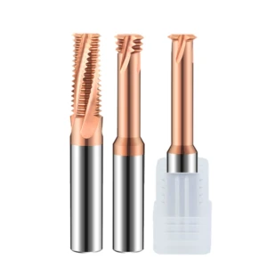
Technical Support for Challenging Applications: A Field Troubleshooting Guide from an HRC65 Thread Mill Manufacturer
Assisting hundreds of machine shops has proven one constant: milling threads at 65 HRC is a system-level process. Tool breakage is rarely solved by swapping brands or dropping spindle speed. Machinists often miss dynamic machine deflection and poor chip evacuation at the hole bottom. As an experienced HRC65 thread mill manufacturer, we know the high stakes of threading finished, hardened die cavities, and systematic troubleshooting is essential.
If you struggle with high scrap rates or thread gauge failures, step back and audit system rigidity. Verify toolholder runout is under 0.003 mm, confirm air pressure clears chips from blind bottoms, and audit your CNC centerline feed conversion. Hard milling has no secrets; isolate the point of mechanical or thermal stress, and broken tools become a thing of the past.
Real-World Case Study (Europe/US Client): Troubleshooting M6 Blind Hole Threading Breakage in D2/SKD11 Stamping Dies (Hardened to 64–65 HRC)
An automotive die shop running vacuum-hardened 1.2379 (D2/SKD11 at 64.5–65.2 HRC) was breaking M6×1.0 thread mills every 1 to 2 holes. They assumed the carbide was too brittle. Spindle telemetry and CAM data revealed they were flood-cooling with a direct 90-degree radial entry. The tool suffered violent entry shock and thermal stress while recutting trapped chips at the hole bottom.
We replaced flood coolant with 0.7 MPa dry air, added a 180-degree helical roll-in path, and reduced entry feed by 40%. We then recalculated the true centerline feed rate to establish reliable thread milling parameters for hardened steel. Tool life jumped past 24 holes per cutter, with thread pitch and surface finish holding well within tolerance.
Resolving Unstable Thread Tolerances: From Tool Wear Offsets to CNC Macro Program Compensation—A Practical On-Site Workflow
In batch production, machinists often face drifting gauge fits. The Go-gauge binds halfway down, but bumping up the D-offset causes the No-Go gauge to pass at the hole entrance. This reverse taper comes from tool deflection as cutting forces rise with wear. Adjusting overall tool radius offsets simply bell-mouths the hole opening without fixing deflection at the bottom.
Fix taper by adding segmented axial compensation or an in-situ zero-depth spring pass in your macro program. Reducing axial depth near the hole bottom and taking a final cleanup cut eliminates residual stock left by tool deflection. If you are struggling with a specific cold-work steel or need advice on toolholder setups, share your drawings, hole depths, and material specs with us to build a proven cutting solution.