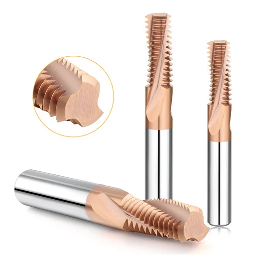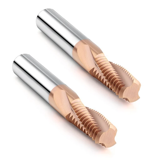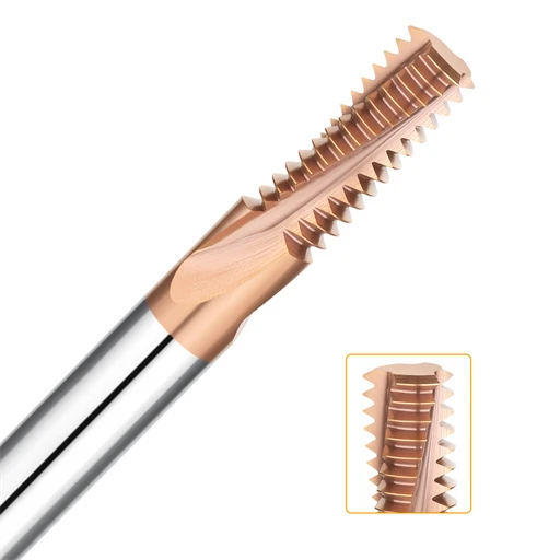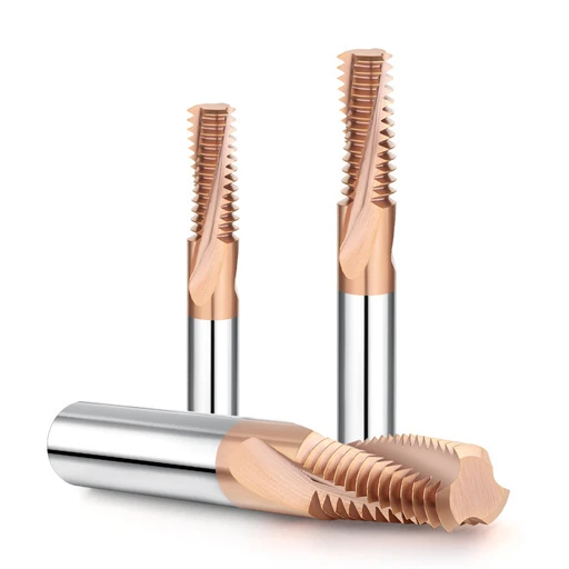


While machining double-cryogenically tempered SKD11 stamping die inserts, a long-time client called us with a critical issue. They were milling M4×0.7 blind-hole threads in stable HRC65 steel. Their solid carbide tool suffered a brittle fracture near the shank root before completing even two full revolutions. The snapped tool jammed deep inside the cavity, putting an expensive pre-hardened die block at risk of being scrapped.
We see this exact breakdown all the time on high-precision shop floors. Working with toolrooms across North America and Europe, we know that threading hardened tool steel exposes tool tips to extreme shear and thermal shock. Many blame substrate toughness or coating quality first. Yet, our SEM fracture analyses show that most thread mill breakage stems from subtle, unmanaged process variables rather than poor raw materials.
Small setup errors trigger severe damage when cutting near the physical limits of tungsten carbide. High overhang ratios induce chatter, uncompensated circular interpolation causes severe thread mill overload, and runout of just 0.003 mm concentrates all cutting forces onto a single tooth. Under HRC65 conditions, these micro-deviations compound instantly into sudden thread mill tool failure.
Have you ever monitored your machine load meter on ultra-conservative parameters, only to hear that dull snap from inside the bore?
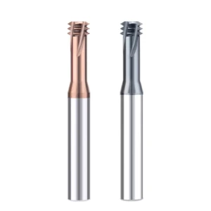
Pilot Hole Preparation and Anomalous Work-Hardened Layers: The Primary Hidden Culprits Behind Thread Mill Overload
Whenever we troubleshoot broken cutters in hardened die blocks, our first instruction to the programmer is simple: step away from the mill and measure the pre-drilled bore. In HRC65 steel, pre-machining defects trigger severe operational spikes. When the tool enters via helical interpolation, hitting an out-of-round or tapered bore causes instant thread mill overload.
We recently analyzed a job where five threaded holes ran clean, but the cutter snapped on the second turn of the sixth hole. Cross-sectional micro-hardness testing revealed that the pre-drilling carbide drill had developed minor flank wear. The resulting friction generated a work-hardened white layer reaching HRC68. The thread mill was not cutting uniform metal; it was slamming into a brittle, irregular shell.
Work-Hardening and Taper Errors: The Root Cause of Instantaneous Chipping in Solid Carbide Thread Mills
When drilling pilot holes in hard stock, slight drill wear turns true shearing into severe burnishing and friction. This intense mechanical deformation leaves a work-hardened surface layer along the inner wall. When rigid solid carbide thread milling cutters engage this altered zone, micro-chipping occurs on the tooth crests. In ultra-hard alloys, an initial micro-crack destroys the cutter within the very next revolution.
Deep-hole chip packing also causes standard drills to deflect, creating an inverted taper where the hole narrows at the bottom. Across our customer test data, a diametral taper of just 0.02 mm over a 10 mm depth drastically ramps up radial engagement. A programmed light cut suddenly turns into heavy flank engagement at the bottom of the blind hole, snapping the tool instantly.
Regarding Thread Milling in SKD11 Steel: Why Must Pilot Hole Diameters Be Enlarged by +0.03 mm to +0.05 mm?
When machining hardened cold-work steels, we always tell programmers to ignore standard handbook drill charts. When thread milling SKD11 steel, DC53, or D2 at HRC65, we intentionally enlarge the pilot hole diameter by +0.03 mm to +0.05 mm. Extremely hard materials display very high shear yield strength. A tight bore creates heavy tool-tip rubbing and dangerous wedging torque.
This adjustment requires an intentional engineering trade-off. Opening the hole slightly lowers theoretical thread engagement height by roughly 5% to 8%. However, pull-out strength in HRC65 materials remains unaffected. The extra radial clearance prevents catastrophic binding, lowers flank heat, and gives chips a safe path out.
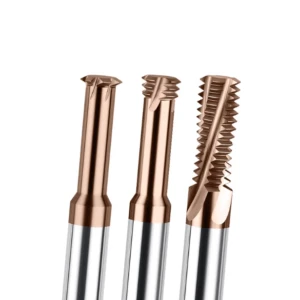
Pitfalls in Radial Depth of Cut (DOC) Strategy: The Impact-Load Trap for Carbide Thread Mills
Milling threads in HRC65 steel is not traditional metal removal. It is high-rigidity micro-peeling. Many shops rely on default CAM library settings that attempt to cut full thread forms in one or two aggressive passes. Once the flutes strike the dense martensitic matrix, normal forces spike on the cutter edge, triggering premature thread mill breaking.
When customers send us fractured tools, the fracture faces almost always display crisp, brittle shear without plastic deformation. Reviewing their G-code reveals radial cuts ($a_e$) that are far too aggressive in the G02/G03 helical blocks. Slender shanks deflect under excessive lateral force, inducing severe flank rubbing that turns a smooth cut into a violent impact.
Heavy Single-Pass Cuts Lead to Tool Failure: In HRC65 Material, a Radial Depth of Cut Exceeding 0.05 mm Is Prohibited
Attempting full profile generation in HRC65 steel with a heavy single pass will almost certainly snap the cutter. Based on cutting-force dynamometer tests, radial cuts deeper than 0.05 mm generate localized shear stresses that exceed the rupture strength of advanced coatings. Excessive lateral engagement places the tool teeth under severe compound stress, leading directly to catastrophic thread mill tool failure.
We prefer an incremental radial pass distribution instead. On an M6 thread with a 0.54 mm profile height, we split the radial engagement into 4 to 6 passes. We start with a 0.04 mm cut, stepping down to 0.02 mm and 0.015 mm finishing cuts. Extra air-cutting passes add a few seconds to cycle time, but they prevent broken tools and saved parts from being scrapped.
Multi-Pass Strategy: The Critical Role of the “Spring Pass” in Compensating for Tool Deflection
When a thread plug gauge fails to seat after milling, operators often instinctively increase the radial tool offset in the control. On high-hardness steel, this is a dangerous mistake. Carbide tools deflect away from the cut under heavy side loads. The undersized pitch diameter is rarely caused by insert wear; it is mechanical tool push-off.
We always mandate at least one zero-depth “spring pass” in the toolpath before adjusting offsets. After reaching final depth, the cutter traces the finished path again without additional radial infeed. This pass cleanly shaves away the micro-stock left behind by tool deflection, ensuring reliable 6H thread gauge fit without causing thread mill breakage.
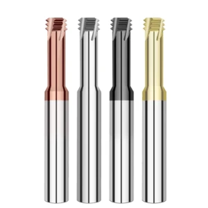
Excessive Tool Runout (TIR): How Minor Deviations Lead to Catastrophic Thread Mill Failure
When milling hardened steel, many machinists focus on speeds and coatings while ignoring toolholder runout. At HRC65, material yield deformation is negligible. Every cutting tooth engagement acts as a violent, micro-scale collision. In soft steel, slight runout merely widens pitch diameter. In hardened steel, runout shifts the entire load onto one tooth, causing sudden thread mill tool failure.
We saw this firsthand at a medical bone-plate mold facility facing a 40% tool breakage rate. Technicians blamed aggressive feed rates. Using a dial indicator on the spindle assembly, we measured 0.012 mm total indicated runout at the tip. One tooth took over 70% of the cutting load while three teeth barely touched metal, snapping the tool on revolution one.
A Tool-Tip Runout Exceeding 0.003 mm Triggers Edge Chipping: Evaluating ER Collets vs Hydraulic Holders
If you run standard spring collets in HRC65 steel, re-verify your setup precision immediately. Tool-tip runout must stay under 0.003 mm; hitting 0.005 mm doubles edge-chipping frequency. Standard ER chucks rely on mechanical clearance across the body, collet, and nut. That design loses repeatability after repeated tool changes, making it the top source of unmanaged thread mill runout.
Toolholder selection requires balancing setup cost against scrap risk. For ultra-hard steel, we prioritize shrink-fit holders and high-precision hydraulic chucks. Both styles reliably hold radial runout under 0.003 mm. Hydraulic chambers also dampen micro-vibrations effectively. The higher holder cost is quickly recouped by eliminating broken tools and scrapped cavity inserts.
Balancing Overhang and Rigidity for Small Thread Mills in M3/M4 Applications
Milling M3 and M4 threads leaves cutters with fragile neck diameters near 2 mm. Carbide delivers exceptional hardness and wear resistance, but its transverse rupture strength drops sharply with overhang. Tool deflection increases cubically with extended length. This makes miniature small thread mills extremely fragile when reaching into deep bores.
On the shop floor, an overhang ratio (L/D) above 3:1 enters a high-risk zone. For deep-cavity work, order custom tools with short cutting flutes and reinforced shanks, or pre-mill a clearance pocket with a larger end mill. Never extend a slender neck further than necessary. Sacrificing single-pass depth for tooling rigidity is essential to prevent unexpected breakage.
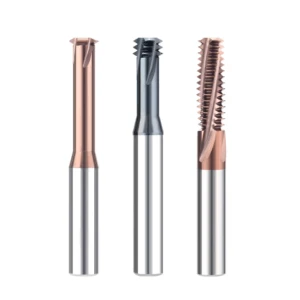
Machining Vibration and Resonant Instability: High-Frequency Thread Milling Chatter
When cutting steel above HRC60, a high-pitched metallic squeal means you should hit feed hold immediately. Self-excited chatter in hardened steel is destructive because the rigid workpiece absorbs almost no impact energy. All cut shocks bounce straight back into the flutes. Intermittent tooth entry that matches spindle or fixture harmonics triggers violent thread milling chatter.
We diagnosed this at a stamping die shop machining HRC64 steel. Workpieces showed heavy white chatter marks and rough, scaly walls. Under a microscope, the cutter displayed jagged, saw-toothed micro-chipping rather than uniform flank wear. Operators blamed tool hardness. In reality, cyclic resonance and high-frequency flutter destroyed the brittle carbide edges within seconds.
Tooth Breakage from Abrupt Phase Shifts: Why Radial Arc-In and Arc-Out Moves Are Mandatory
Reviewing customer NC programs often exposes a major flaw: plunging straight into the bore wall with a G01 linear move. Linear entry forces the contact angle from 0° to wide engagement instantly. This transient shock strikes the tool tip like a hammer blow. The violent phase shift snaps flutes and causes sudden thread mill breakage.
Always program smooth 90° or 180° circular arc-in and arc-out motions. A helical or circular arc entry starts chip engagement at zero and builds load gradually. This ensures cutting resistance rises smoothly rather than spiking. An arc exit similarly prevents a hard stop at the finish point, avoiding shock loads and deep dwell marks.
Chatter-Induced Micro-Crack Propagation: Avoiding Resonance Zones by Fine-Tuning Speeds and Feeds
If you hear loud harmonic squeal during test cuts, never try to power through the cycle. High-frequency chatter transmits acoustic stress deep into the carbide substrate within milliseconds. These shockwaves turn sub-micron grain defects into visible micro-cracks. Once cracks spread from the edge toward the core, sudden thread mill tool failure is inevitable.
Dropping spindle speed drastically is often counterproductive. Lowering RPM increases chip load per tooth, raising cutting forces and locking the tool into harsher vibration nodes. Instead, adjust spindle speed by 50 to 100 RPM increments while trimming feed rate by 10% to 15%. This shifts harmonic excitation frequencies, moving the cut into a quiet, stable window.
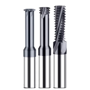
Flaws in Feed Rate Calculation: Overlooking Instantaneous Thread Mill Overload
Skilled machinists who calculate linear milling feeds accurately often make mistakes on internal helical paths. During G02 or G03 circular interpolation, the programmed F-value governs tool center-line velocity, not the outer tooth tip. Calculating feeds without internal radius compensation causes actual edge loads to spike wildly, creating severe thread mill overload.
In soft steel, workpiece ductility masks this calculation error. In HRC65 steel, uncompensated feeds are fatal. Operators often believe they programmed conservative parameters, unaware that the actual chip load at the bore wall exceeds safe structural limits. This math oversight remains a primary cause of sudden tool failure in hardened materials.
Control System Linear Feed vs Actual Tip Feed: The Algorithmic Flaw That Spikes Chip Load
When interpolating inside a bore, the tool center path is much shorter than the outer cutting edge path along the wall. By kinematic ratio, cutting edge velocity scales by (D_hole – D_tool) / D_hole. If the programmer fails to compensate the feed rate, the CNC pushes the cutting flutes several times faster than intended, destroying the thread mill bit.
For example, using a 6 mm thread mill inside an M8 hole multiplies the true tooth feed by 3 to 4 times over the programmed center feed. You might expect a conservative cut, but the teeth strike the wall under destructive chip thickness. At HRC65, carbide teeth cannot survive half a turn under this load before snapping off completely.
Achieving a Safe 0.01–0.02 mm Feed-Per-Tooth Window for Thread Milling Hardened Steel
When cutting extreme hardness, chip thickness must stay within strict tolerances. Based on extensive dynamometer and tool-life data, the true compensated feed per tooth for thread milling hardened steel must remain locked between 0.01 mm and 0.02 mm/tooth. Exceeding 0.025 mm/tooth accelerates edge fracture, while dropping below 0.005 mm/tooth causes abrasive rubbing and rapid flank wear.
Build automatic radius compensation into your CAM post-processors or machine macro routines. This ensures the output F-value calculates centerline speed directly from the contact point’s true tangential velocity. Keeping actual feed near 0.015 mm/tooth slightly extends cycle time, but it protects expensive workpieces and prevents premature tool breakage.
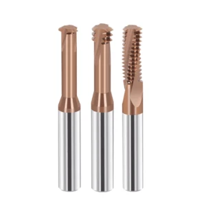
Incorrect Selection of Chip Evacuation and Cooling Media: High-Pressure Air vs. Oil Mist
Flooding the cut with water-soluble coolant is standard practice for soft steels, but HRC65 metal completely upends conventional cooling logic. Swarf at this hardness consists of ultra-fine, abrasive glass-like particles rather than continuous curled ribbons. If your fluid dynamics cannot flush these particles out, or if thermal shock fractures the tool, severe thread mill tool failure occurs within seconds.
We tested this across several European mold facilities. One group used high-volume flood emulsion, while the other ran dry chilled air with minimum quantity lubrication (MQL). The flood-cooled machines chipped cutting edges within three holes. Conversely, pneumatic evacuation multiplied tool life several times over. Evacuating chips cleanly and stabilizing thermal cycles matters far more than simply flooding the cut with liquid.
Secondary Chip Crushing: How Hardened Micro-Chips in Blind Holes Snap Cutters
Blind-hole threading offers almost no natural escape route for debris. When cutting HRC65 steel, detached micro-chips undergo extreme shear strain and friction, work-hardening to the hardness of the carbide substrate itself. If these loose abrasive particles settle at the bottom of the bore, the helical path of the thread mill bit crushes them against the cavity floor.
This re-cutting creates sudden step-load surges rather than linear wear. Operators usually find that the tip flutes shatter into powder before the solid shank shears off clean. We recommend directing an external air nozzle straight into the bore at 0.6 MPa minimum. Even better, run through-tool air to keep chips suspended and airborne until they exit the hole completely.
Preventing Thermal Shock: How MQL and Chilled Air Protect Carbide Coatings
Flooding ultra-hard steel with water-based coolant induces severe thermal shock. In interrupted cuts, flutes cycle between 800°C friction zones and sudden cold coolant flushes dozens of times per second. This rapid temperature cycling generates dense vertical comb cracks across brittle carbide edges, causing rapid thread mill breakage.
Dry chilled air paired with MQL provides the best balance on the shop floor. Chilled air expels abrasive dust and manages macro-heat without shock. Meanwhile, vegetable-oil micro-droplets create a thin lubricating boundary that prevents high-temperature galling. Although MQL requires dedicated filtration, it eliminates thermal fatigue spalling and keeps your tool coatings intact.
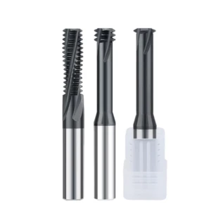
Substrate Grain Structure and Coating Delamination: Material Property Mismatches
When runout, feeds, and chip evacuation are dialed in but cutters still snap unexpectedly, the metallurgical structure of the tool blank is usually at fault. Cutting HRC65 steel pushes tungsten carbide to its ultimate shear and thermal limits. Any micro-voids, cobalt pooling, or weak coating adhesion will concentrate stress and trigger catastrophic thread mill tool failure.
In our testing lab, we analyze broken tools using SEM and EDS fracture analysis. Technicians routinely blame aggressive speeds, but micro-imaging frequently uncovers porous substrates, binder migration, and delaminated coatings. Matching the wrong grade to ultra-hard steels produces poor results. It is the functional equivalent of striking hardened alloy with brittle glass.
Submicron Grain Substrates (0.2–0.4 μm) and Transverse Rupture Strength in Hardened Steel
A common industry mistake is assuming that harder carbide always cuts hard steel better. Chasing HRA94 hardness, low-end rod suppliers often reduce cobalt binder content below 6% or use uneven submicron grain blends. While hard at room temperature, their Transverse Rupture Strength drops well below the safe 3500 MPa threshold, making the thread mill breaking inevitable under cutting shock.
SEM fractography reveals clean, brittle intergranular cleavage without the dimpled shear ridges that arrest crack growth. Cracks travel along carbide grain boundaries at extreme speeds, shattering the tool core. For HRC65 cuts, we specify ultrafine substrates with 8% to 10% cobalt and a minimum 4000 MPa TRS. Controlled bimodal distributions absorb intermittent impact energy effectively.
Why Quality Thread Milling Cutters Manufacturers Rely on High-Temperature Nanocomposite Coatings
Shear zones in HRC65 steel regularly exceed 900°C at the cutting interface. Standard PVD coatings like AlTiN or TiAlN oxidize rapidly around 800°C, causing the protective film to blister and peel away. Once that thermal barrier fails, the bare carbide edge rubs directly against hard steel, causing swift adhesive wear. Reliable thread milling cutters manufacturers therefore rely on AlTiSiN nanocomposite coatings rated past 1100°C.
Silicon doping interrupts standard columnar crystal growth, creating an amorphous silicon nitride matrix that encapsulates ultra-fine grains. Under cutting friction, this surface forms an aluminum-silicon oxide passivation layer that lowers friction below 0.35. While vacuum deposition for nanocomposites costs more, the resulting crater resistance and thermal shield prevent chipping inside deep holes.
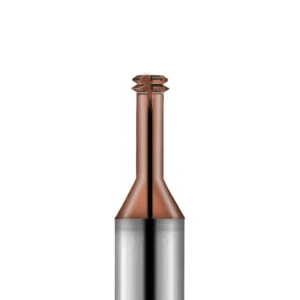
On-Site Rapid Troubleshooting Checklist: Shop-Floor Protocol for Thread Mill Breakage
When an expensive HRC65 workpiece is on the table, guessing and loading another tool is the worst reaction. In precision facilities, our core protocol is simple: stop the spindle, inspect the fracture face, and systematically audit the failure mode. Resolving chronic thread mill breakage requires pinpointing hidden process imbalances across the machine, program, and toolpath in minutes.
Ultra-hard threading permits zero margin for error. A work-hardened pilot hole, a few microns of holder runout, or an uncompensated circular feed will snap a tool tip instantly. Instead of scrapping expensive blocks, run through this practical checklist to audit every physical variable from the spindle taper to the hole bottom.
Listen, Inspect Chips, and Measure Runout: The 3-Minute Failure Diagnosis
If you do not have cutting dynamometers on the floor, use our simple three-minute sensory check to diagnose tool failure:
-
Listen to entry and exit sounds: If you hear high-pitched chatter upon hole entry, check your G-code for missing arc-in moves or uncompensated centerline feeds. If the tool snaps near the floor, verify whether a zero-depth spring pass is missing or if the retraction arc clips the wall.
-
Inspect swarf and fracture faces: If you find black, pulverized dust in the bore, increase air pressure or switch to through-spindle air to prevent chip packing. A flat, clean break at the shank indicates radial overload, while micro-chipped teeth point to thermal shock from flood coolant.
-
Measure tool-tip runout: If you are setting up a replacement tool, sweep an indicator across the cutting flutes over a full spindle revolution. If total indicated runout exceeds 0.003 mm, clean the taper or swap to a hydraulic holder to stop thread mill runout from overloading a single tooth.
Threading hardened tool steel requires balancing heat-treat condition, spindle rigidity, and flute geometry. If you are struggling with tool breakage in cryo-treated SKD11, DC53, or PM steels, share your bore depths, tool overhang, and cutting parameters with us. We can review your drawings and machining data together to stabilize the process.