



We recently machined M4 internal threads into heat-treated S136 mold steel at near HRC65 hardness. The core challenge was not just cutting the profile. It was maintaining tight pitch diameter tolerances, clean crest forms, and uniform surface finishes across thousands of parts.
Initial trial cuts looked acceptable on the optical comparator. However, batch production quickly revealed dimensional drift, chatter marks on thread flanks, and micro-chipping on cutting edges. Isolating single parameters failed to solve the issue. The real bottleneck was an unstable balance between tool overhang, core rigidity, and radial chip load.
Small-diameter internal threads amplify every mechanical flaw during thread milling hardened steel. Miniature thread mills lack lateral stiffness, making tool deflection and radial runout severe. When speeds, feeds, or toolpath entries are miscalculated, edge breakdown happens rapidly.
Tool geometry alone cannot guarantee process capability. Even with premium ultra-fine carbide, tool wear and broken cutters occur if cutting parameters remain uncalibrated. Process stability demands dampening vibration while maintaining sufficient chip thickness to prevent abrasive rub on hardened martensite.
Successful thread milling HRC65 steel starts with rigorous tool selection. We evaluate sub-micron carbide grades, multilayer AlTiN/AlCrN coatings, flute core thickness, and cutting edge prep before touching the machine. These choices must match part clamping rigidity, gauge length, and machine spindle health.
Dynamic factors dictate tool life in ultra-hard alloys. We control tool runout under 0.003 mm, apply helical arc-in strategies, and minimize radial depth of cut. Limiting tool deflection preserves crest geometry and eliminates chatter during deep-hole cuts.
We never rely on generic catalog parameters for thread milling hardened steel. Even at identical Rockwell ratings, heat-treated S136 cuts differently than D2, CPM-10V, or cemented carbide inserts. Material grain structure, hole depth, and machine tool acceleration curves change cutting forces completely.
Reliable production relies on physical validation rather than catalog numbers. We dial in cutting speeds and feed per tooth using trial-cut harmonics, tool flank wear scans, and thread plug gauge feedback. This empirical approach delivers repeatable thread quality and lowers consumable costs.

Thread Milling HRC65 Steel – Common Issues in Actual Production
Machining HRC60–65 hardened steels rarely fails on the very first part. Instead, problems surface during extended runs. Common symptoms include pitch diameter drift, crest profile distortion, flank chatter, and micro-chipping along the cutting edge. Small-diameter internal threads like M4 or M5 make these defects worse due to reduced core cross-sections. Rather than blaming material hardness alone, we evaluate runout, gauge length, and chip load.
Never validate a production run based solely on the first part off the machine. During continuous thread milling HRC65 steel, we track plug gauge resistance trends and monitor spindle load curves in real time. We also inspect the flanks under high magnification for micro-chipping and flank wear bands. These telltale signs reveal whether instability stems from radial deflection, thermal cycling, or inadequate toolholder clamping.
Why Chipping and Dimension Drift Occur When Thread Milling HRC65 Steel
On a recent mold core project, initial threads checked true with a Class 6H plug gauge. After 15 holes, the NO-GO gauge began to bind on entry. The miniature cutter had not broken, but the cutting edges displayed microscopic micro-spalling along the primary relief. The tool had lost geometric stability under sustained cutting pressure and harmonic resonance. Judging tool life on part one leads to severe wear underestimation.
When pitch diameters drift during continuous thread milling HRC65 steel, avoid making rapid feed or speed compensations in the CNC control. First, inspect radial runout at the edge, gauge length overhang, and radial depth of cut per pass. Edge chipping almost always pairs with high-frequency chatter and irregular chip curl. With miniature tools, always sacrifice cycle time to stabilize edge load.
Key Operational Factors When Machining HRC60–65 Hardened Steel
Always measure surface hardness with a calibrated benchtop tester before cutting. Two blocks of S136 or D2 can vary significantly across heat-treatment batches, drastically shifting chip resistance. Next, calculate exact hole depth, minor diameter tolerance, and clearance for blind holes. In hardened martensitic steels, these dimensions dictate flute chip evacuation space, core deflection, and overall cycle strategy.
Single-hole trials never confirm process capability for high-volume thread milling hardened steel. Miniature tools experience cumulative thermal stress and micro-abrasion that accelerate sharply after initial passes. We document thread pitch diameters, finish quality, and corner wear at scheduled part intervals. In the HRC62–65 zone, empirical cutting data must replace conventional cutting charts.
How Tool Characteristics, Machine Rigidity, and Workholding Affect Machining Stability When Thread Milling HRC65 Steel
Poor workholding often masquerades as premature tool failure. A premium sub-micron carbide tool will still fail if holder runout exceeds 0.003 mm or excessive stickout causes flex. In small-diameter internal threading, that vibration induces catastrophic edge chipping. Switching brands or coatings will not fix poor mechanical fundamentals. We always choke up on tool shank stickout and qualify hydraulic chuck runout first.
Process stability during thread milling HRC65 steel relies on the entire structural loop. Machine spindle bearing preload, shrink-fit holding, fixture damping, and tool core stiffness function as one interconnected unit. If a verified process cuts cleanly on one machining center but chatters on another, check structural rigidity and spindle runout. The tool is rarely the sole culprit.
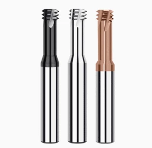
How to Select an HRC65 Carbide Thread Mill for Stable Hardened Steel Machining
When quoting hardened steel projects, we never pick tooling based on hardness alone. We evaluate thread specs, hole depth, tool diameter, overhang, and machine rigidity. This is crucial for small internal threads with weak core cross-sections. Using an overly long tool for deep holes guarantees vibration and dimensional drift. An HRC65 carbide thread mill is engineered for core strength and edge stability, not just adopting standard steel geometries.
We always ask three questions before starting an HRC65 internal threading job. Can the tool handle the hardness? Is the size right for the pitch? Can the workholding stay rigid? Only after securing these do we adjust feeds, speeds, and radial depths. Tool selection is about building a stable machining system. This ensures repeatable accuracy for thread milling hardened steel.
How Carbide Substrate and Cutting Edge Geometry Affect HRC65 Hardened Steel Machining
Carbide strength and edge prep are vital for thread milling HRC65 steel. Harder isn’t always better if the edge lacks structural support. A razor-sharp edge will instantly micro-chip under heavy radial cutting forces. We saw this on an HRC65 mold block, where tiny edge nicks quickly ruined thread gauges. Adding a slight edge hone immediately stabilized the process.
Always look beyond just the carbide grade when evaluating an HRC65 carbide thread mill. Check the core diameter, radial relief, and cutting edge reinforcement. Dedicated hard milling tools use thicker cores to absorb extreme cutting loads. If micro-chipping happens, do not just drop your feed rates. Verify that the tool geometry actually matches your severe cutting conditions first.
Selecting an HRC65 Thread Mill Based on Thread Size, Pitch, and Thread Depth
Thread size, pitch, and depth dictate our initial tool screening. Machining M4 and M10 threads in HRC65 require entirely different tooling strategies. Pushing an M6 thread from 6mm to 20mm deep drastically changes rigidity requirements. We select cutter diameters based on max thread depth, not just outer diameter. Reliable tools for thread milling hardened steel explicitly list their maximum pitch and depth ratings.
For deep, small-diameter holes, minimizing effective overhang is our top priority. If a long reach is required, we heavily scrutinize the tool’s shank diameter and holder stiffness. Small threads like M4 amplify the destructive effects of minor runout. We prefer adjusting pilot hole sizes over using weak, extended-reach cutters. We never risk a scrapped part just to thread a deep hole in a single pass.
Matching Flute Count, Helix, and Coating for HRC65 Hardened Steel Thread Milling
We evaluate flute count, helix angle, and coatings as a complete package. For setups prone to chatter, we use variable helix designs to break harmonic resonance. For continuous cuts, thermal-resistant AlTiN or AlCrN coatings are mandatory. Many tools for thread milling HRC65 steel combine these features to survive high-heat zones. However, a “hard steel” label doesn’t guarantee success in every setup.
Small diameters and deep reaches create unique machining challenges. We analyze chip evacuation space, edge length, and spindle condition before trusting a coating. If rapid wear happens without chatter, we review coating limits and chip loads. If harmonic chatter marks appear, we check helix angles and overhangs. Swapping coatings won’t fix underlying rigidity problems during thread milling hardened steel.
Controlling Tool Overhang and Runout When Milling Internal Threads in Hardened Steel
Tool overhang and runout tolerances must be perfectly tight for HRC65 alloys. We once had a premium tool fail because the hydraulic chuck introduced runout. This caused single-flute dragging and rapid dimensional drift on small holes. Sliding the shank deeper into the holder instantly cured the instability. Qualify your spindle and toolholder before tweaking parameters for thread milling HRC65 steel.
Minimize effective overhang while maintaining full clamping contact inside the holder. We physically dial-indicate tool runout after clamping instead of trusting factory specs. Even 0.0005 inches of clamping eccentricity will destroy a micro-thread mill in HRC65 steel. Precision shank tolerances paired with high-end shrink-fit holders are essential. Clamping accuracy dictates tool life and thread quality for thread milling hardened steel.
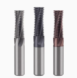
Thread Milling Process: Machining Internal Threads in HRC 65 Hardened Steel
Machining internal threads in HRC 60–65 steel is a coordinated sequence, not a single roughing pass. Pilot hole sizing, entry arcs, helical interpolation, and retraction paths must work seamlessly together. Unstable toolpaths introduce sudden shock loads that crack brittle carbide teeth instantly. Blind holes require extra care to flush out micro-chips before the cutter recuts them. Most tooling issues trace back to flawed entry trajectories rather than cutting parameters.
We verify every step in the pipeline before cycling the spindle: pre-hole check, arc-in, helical cut, tangential retract, and plug-gauge inspection. The kinematics demand perfect synchronization across the X, Y, and Z axes. One complete helical revolution must precisely match one thread pitch. Any stutter in CNC control look-ahead creates severe tool deflection during thread milling hardened steel.
Determining Hole Diameter and Thread Engagement in the Thread Milling Process
Never calculate pilot hole diameters based solely on nominal tap drill charts. In HRC65 tool steel, hole diameter, pitch, thread depth, and cutter core diameter dictate the actual chip load. An undersized bore overburdens the cutter’s radial engagement, risking immediate tool breakage. An oversized hole weakens thread percentage and distorts profile accuracy. We verify bore diameters with pin gauges after hard-drilling or EDM operations.
Radial engagement dictates tool survival when thread milling HRC65 steel. We never force miniature thread mills to take full radial depth in a single pass. Splitting the cut into multiple radial step-overs keeps chip thickness consistent and eliminates shock loads. Keeping radial engagement low prevents tool deflection and chatter marks on the thread crests.
How Do We Design the Helical Toolpath in Internal Thread Milling Hardened Steel?
Program validation in CAM starts with checking the tool center path against pitch increments per Z-revolution. Plunging directly into the wall produces an aggressive load spike. This sudden impact chips the fragile carbide edge and gouges the thread entry point. The cutter must blend into the thread flank gradually.
We design smooth tangential arc-in and arc-out toolpaths for internal thread milling hardened steel. A gradual 90-degree or 180-degree sweep eases the tool into the cut, ramping up radial pressure smoothly. Tangential lead-ins prevent shock loading, which is far more effective than simply reducing spindle RPM. A continuous exit path similarly avoids edge chipping during tool retract.
Adjusting Climb Milling, Entry, and Exit for Thread Milling HRC65 Steel
Climb milling is our default method for internal threads in high-hardness tool steels. Down-milling forms thick chips at entry and thins them out at exit, which dampens cutting vibration. For right-hand internal threads, we run upward helical interpolation from the bottom of the bore using G03 arc moves. This keeps cutting forces steady and yields excellent flank surface finishes.
Entry and exit motions require extreme care on small threads like M4 and M5. Abrupt straight-line retractions cause sudden release chatter that chips cutting edges. If teeth fail at the entry mark during thread milling HRC65 steel, we review the arc radius and radial depth per pass. Smooth roll-in and roll-out moves ensure long-term stability during continuous production.
Controlling Tool Load and Chip Evacuation During Deep Thread Milling of HRC65 Steel
Deep internal threads compound the risks of tool deflection and chip packing. Extended tool stickout lowers lateral stiffness, making chatter almost unavoidable. Trapped chips at the bottom of blind holes get recut, destroying both the thread profile and the tool edge. On one HRC62 mold core, flank tearing stopped completely once we fixed bottom-hole chip clearing.
We run high-pressure through-spindle air blasts rather than flood coolant during deep thread milling hardened steel. Dry cutting with air prevents thermal shock while clearing hardened micro-chips instantly. We also use smaller radial step-overs to offset the loss of tool rigidity at extended overhangs. Steady helical moves protect slender shanks from dangerous lateral bending forces.

Determining Thread Milling Speed and Feed Parameters for HRC65 Steel
We never treat speeds and feeds as isolated values in HRC60–65 steel. We calculate them alongside thread diameter, pitch, flute count, and fixture rigidity. Tool manufacturer catalogs offer baseline starting windows, but they cannot account for real-world setup flex. We combine supplier data with part hardness to establish a conservative baseline before cutting.
A tool may cut several holes cleanly before thermal stress and edge breakdown suddenly spike. Lowering the table feed blindly rarely solves premature wear. Instead, we re-evaluate cutter core deflection and radial width of cut. Dialing in thread milling speeds and feeds requires continuous feedback from trial cuts and tool wear audits, not static handbook charts.
Determining Thread Milling Speed and Feed Based on Thread Diameter, Pitch, and Tool Diameter
Parameter calculations always start with the thread pitch and major diameter. Thread size determines cutter diameter, while the pitch sets axial travel per helical revolution. With miniature cutters, we never increase feed-per-tooth just to shave seconds off the cycle. Even minor shock loads in HRC65 alloys cause catastrophic micro-fractures along brittle carbide edges.
We use manufacturer chip load tables as initial references, then derate them to match setup rigidity and gauge length. Machine builders recommend calculating chip thinning and derating surface footage for extreme alloys. We establish a reliable starting baseline, then verify gauge fit and tooth condition before pushing thread milling speeds and feeds.
Balancing RPM, Feed Rate, and Chip Load for HRC65 Thread Mills
Balancing spindle speed and feed per tooth prevents thermal cracking during thread milling HRC65 steel. Running high RPM generates extreme friction that degrades cutter coatings within seconds. Conversely, an overly light feed causes the cutting edge to rub and burnish instead of shear. The edge must positively penetrate the hardened martensite without pounding the tool core.
When tools show thermal breakdown, we inspect surface speed and air blast pressure first. If edge chipping appears, we verify feed per tooth, radial engagement, and tool stickout. We adjust only one cutting variable at a time to isolate process improvements. Dedicated tooling for thread milling hardened steel demands precise coordination between edge geometry and programmed feed rates.
Adjusting Radial Engagement and Step-over for Machining HRC65 Hardened Steel
Lowering spindle speed is not the primary way to reduce cutting force in HRC65 steel. Radial step-over dictates instantaneous chip load on each tooth far more than surface footage. Excessive radial engagement spikes bending forces, while too little engagement leads to work-hardening and tool rub. Incremental radial passes protect fragile tool profiles.
On a tight-tolerance HRC65 project, cutting edges chipped after twenty parts despite steady RPM. Reducing radial step-over per pass stabilized cutting forces and eliminated tooth failure. Before altering speeds or feeds, verify your finish pass allowance. Multi-pass radial strategies drastically lower cutting pressure and prevent deflection during thread milling hardened steel.
Distinguishing Between Parameter Issues and Tool Issues in Thread Milling
We never diagnose tool problems using spindle sound or single-hole results alone. When thread tolerances drift, we inspect flank wear bands under a shop microscope and swap in a fresh cutter. If a new tool immediately restores tolerance, edge wear was the bottleneck. If the new cutter fails the same way, we audit toolpath geometry, radial engagement, and spindle runout.
When parameter tweaks only fix the first two holes before chatter returns, the problem is mechanical. We immediately inspect holder runout, shank clamp depth, and chip evacuation. Adjusting thread milling speeds and feeds cannot compensate for holder eccentricity or machine vibration. Long-term batch stability always takes priority over single-hole cycle times.
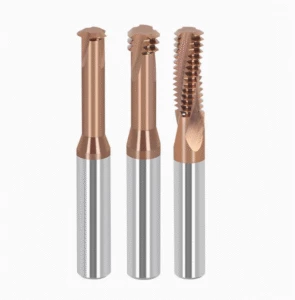
S136 Hardened Steel Thread Milling – A Real-World Case Study: M4 Threading at HRC65
We recently tackled an injection mold core requiring internal M4×0.7 threads in S136 ESR stainless steel heat-treated to near HRC65. The first article checked clean with a Class 6H plug gauge. However, after twenty parts, pitch diameters began drifting off-spec and the cutting teeth showed micro-spalling. Machining micro threads in extreme alloys is never about surviving the first cut; it is about sustaining dynamic stability through full production.
Rather than condemning the carbide grade, we audited bore size, overhang, collet runout, and radial depth per pass. For successful S136 hardened steel thread milling, evaluating heat-treat temper and effective reach is critical. Miniature M4 cutters leave zero room for mechanical error. Hardened steel threading demands balancing core deflection, chip evacuation, and holder rigidity as one system.
S136 Hardened Steel Thread Milling – Actual Machining Conditions for M4 Threading at HRC65
We started by testing actual surface hardness with a calibrated benchtop tester instead of trusting the material mill sheet. In quench-and-tempered S136 at HRC65, we verify pitch, minor diameter, and blind-hole bottom clearance before programming. An M4 tool has a slender neck; mismatched pre-drilled holes or excessive thread depths guarantee broken tools regardless of feed adjustments.
We validate process capability by monitoring wear progression across continuous production cycles. Our team inspects pitch diameter growth, flank burrs, and cutting edge spalling under an optical comparator. Early dimensional drift flags premature edge chipping or setup deflection rather than incorrect table speeds. For high-yield S136 hardened steel thread milling, we lock in process stability before optimizing cycle time.
Addressing Rigidity Issues with Small-Diameter Thread Mills for M4 HRC65 Thread Milling
Miniature M4 thread mills lack core cross-section, making them vulnerable to lateral deflection under cutting pressure. Excessive tool stickout lowers dynamic stiffness and induces high-frequency chatter. We once traced rapid dimensional drift to 0.006 mm of holder runout. That minor runout forced one tooth to take the entire chip load, causing rapid failure during thread milling HRC65 steel.
We minimize gauge length by choking down on the tool shank inside precision hydraulic or shrink-fit holders. Slender cutters must never be overextended simply to clear fixture clamps. If a deep thread reach is unavoidable, we step down radial passes to offset bending moments. Rigidity and minimal overhang protect micro-carbide tooling from cyclic fatigue.
Troubleshooting Runout and Toolpaths When Dimensional Deviations Occur in M4 HRC65 Thread Milling
When M4 thread pitch diameters drift, never jump straight to adjusting diameter wear offsets on the CNC control. Measure assembled tool runout at the cutting teeth and inspect the primary relief for micro-fractures. If runout exceeds 0.003 mm, one flute will carry the entire radial load, causing premature tool breakdown during thread milling hardened steel.
If runout passes inspection, evaluate your CAM interpolation paths and lead-in vectors. Replace direct radial plunge entries with smooth 90-degree tangential arc-ins to ramp cutting pressure gradually. Instantaneous impact loads snap fragile carbide teeth at the hole entry. Smooth tangential entry and steady climb milling eliminate shock loading in ultra-hard tool steels.
Balancing Thread Accuracy and Tool Life When Machining S136 (HRC 60–65)
Accuracy and tool life are tightly linked in hardened stainless mold steels. Underfeeding the cutter causes burnishing, work-hardening, and extreme frictional heat. Overfeeding spikes radial forces and chips tooth crests. Our priority for S136 hardened steel thread milling is finding the sweet spot where tool wear remains linear and pitch diameters hold steady.
We define tool life by the number of continuous holes passing gauge inspection, not theoretical formulas. If pitch diameters drift after fifteen holes, we reduce radial step-over rather than slowing surface footage. Predictable tool wear prevents unexpected tool breakage and protects expensive mold inserts. Process repeatability across entire shifts is the true hallmark of hard milling expertise.

HRC65 Thread Mill Tool Life – Determining When the Tool Is Nearing the End of Its Life
We never define carbide cutter longevity strictly by hole count in HRC60–65 steel. Tool wear rates fluctuate wildly based on gauge length, holder runout, and hole depth. Tool degradation follows a clear timeline: initial coating burn-off, steady abrasive flank wear, micro-spalling, and final profile collapse. Tracking early wear indicators prevents disastrous tool breakage inside high-value parts during thread milling hardened steel.
Do not rely only on visual thread inspection to gauge cutter health. We monitor plug gauge drag, pitch diameter drift, acoustic pitch, and spindle load meters simultaneously. Catching subtle dimensional trends early is critical on small-diameter internal threads. If consecutive holes trend toward the tolerance limit, pulling the tool before catastrophic failure protects the part.
Determining HRC65 Thread Mill Tool Life via Edge Wear and Thread Size Changes
On an HRC65 mold insert, threads passed initial inspection before the GO plug gauge grew tight around hole twenty. Optical inspection revealed steady primary flank wear that was invisible to the naked eye. Synchronizing thread dimensional inspection logs with cutting edge audits pinpointed the exact end of tool life. Early dimensional drift serves as the clearest warning sign when managing HRC65 thread mill tool life.
Set up standardized gauging intervals throughout production runs to catch wear trends. Record pitch diameters, plug gauge engagement depth, and flank finishes at regular part milestones. When pitch diameter steadily drifts alongside minor relief land rubbing, the carbide has entered rapid late-stage wear. This data-driven audit is far safer than gambling on fixed tool-change intervals.
Distinguishing Between Normal Tool Wear, Edge Chipping, and Abnormal Wear
Normal wear appears as uniform, gradual abrasive smoothing across all flutes. When flank wear develops evenly and thread tolerances hold, the tool can safely stay in the cut. Conversely, notched teeth, micro-flaking, or one-sided tooth wear signal severe dynamic instability. Micro-chipping must be addressed instantly because it quickly leads to cutter snapping during thread milling HRC65 steel.
Part surface finish immediately reflects underlying cutting edge conditions. Normal wear shifts pitch diameter gradually, while abnormal wear causes harmonic chatter, flank tearing, and screeching cuts. If a cutter fails prematurely with chipped teeth, do not blame tool quality alone. Check assembly runout, radial depth per pass, entry vectors, and fixture stiffness.
Machining Conditions Associated with Reduced Tool Life When Thread Milling HRC65 Steel
Premature cutter death rarely stems from a single isolated variable. High surface footage triggers thermal cracking, while insufficient chip load causes rubbing and severe work-hardening. Heavy radial depth creates destructive shock loads, and excessive tool overhang induces chatter that fractures brittle carbide flutes. These hidden mechanical stresses compound rapidly over extended runs during thread milling hardened steel.
When tool life drops unexpectedly, audit your current setup against baseline production logs. Check whether hole depth increased, gauge length slipped, or an operator bumped feed override switches. Never accept an adjustment that improves tool life at the expense of flank finish. Swapping chipping for abrasive rubbing simply exchanges one failure mode for another.
Establishing Tool Life Records for HRC65 Thread Mills Using Actual Machining Data
We correlate tool tracking logs directly to finished thread dimensions rather than raw cycle counts. A production record should capture part hardness, pitch, bore depth, toolholder style, overhang, and cutting parameters. Pairing tool microscopy photos with pitch diameter inspection sheets links cutter breakdown directly to part quality. This system creates an empirical baseline for maximizing HRC65 thread mill tool life.
Start building your internal tool life database on high-volume, stable production jobs. Inspect cutting teeth and log thread gauge fit after fixed intervals to chart precise wear curves. These trends clearly show when flank wear accelerates and when to swap tools safely. Empirical tool-change windows eliminate scrap parts, protect machine spindles, and maximize shop floor profitability.
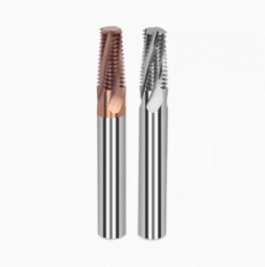
Thread Mill Breakage – Why Tools Break When Machining HRC65 Hardened Steel
Catastrophic tool snapping in HRC60–65 alloys follows distinct failure modes. Some cutters shatter immediately upon entry, while others break after several good parts. Many failures blamed on aggressive feeds actually stem from radial runout or flawed CAM motion. We treat tool failure as a system breakdown across the cutter, holder, spindle, and programmed toolpath.
Miniature threads like M4 and M5 demand precise failure logging during thread milling hardened steel. Document the exact coordinate, interpolation phase, and part count where fracture occurs. Snapping on initial engagement points to impact shock, while failure during helical passes suggests chip packing or flex. Identifying the failure point uncovers root causes faster than blindly replacing tools.
Key Machining Conditions to Check When Thread Mills Break
Always inspect fracture surfaces under high magnification before editing CNC programs. Inspect the tool shank for fretting, flutes for micro-spalling, and relief lands for one-sided rubbing. Shank fractures indicate excessive overhang, severe runout, or clamping slippage. Flute-level breaks point toward excessive radial engagement or buried chips.
One customer attributed tool snapping to aggressive feed rates on an HRC64 mold core. Physical inspection revealed the pre-drilled bore was undersized by 0.15 mm, causing severe radial overload. Resizing the pilot hole eliminated broken tools completely without slowing down cycles. Always troubleshoot in strict order: tool condition, holder runout, pilot bore, toolpath geometry, and finally thread mill breakage.
The Relationship Between Edge Chipping/Breakage and Tool Runout for HRC65 Thread Mills
Small-diameter carbide tools are extremely sensitive to radial eccentricity. Assembled runout over 0.003 mm concentrates cutting pressure entirely onto a single flute. That overloaded tooth micro-chips first, throwing the tool out of balance and causing catastrophic fracture. Precision shrink-fit or hydraulic toolholders are mandatory for thread milling HRC65 steel.
We once diagnosed intermittent tool breakage on a multi-flute micro cutter that passed benchtop inspection. The standard collet chuck introduced 0.008 mm of dynamic runout at gauge length. Switching to a high-precision hydraulic holder completely resolved edge spalling and dimensional drift. When flutes chip on one side, check holder concentricity rather than adjusting cutting RPM.
Is Thread Mill Breakage Caused by Speed, Feed, Engagement, or Toolpath?
Never change multiple machining variables at once when troubleshooting tool failure. Adjusting surface footage, table feed, and radial depth together obscures the root cause. Inspect the fracture zone to identify whether failure was thermal or mechanical. Pure mechanical breakage shows clean fractures, while thermal failure shows blackened, spalled coatings.
If teeth chip without flank burnishing, inspect radial step-over, entry arcs, and holder runout. If cutting edges display severe thermal wear, evaluate air blast pressure, surface footage, and chip clearance. Breakage on entry or exit almost always points to linear CAM plunges. Smooth tangential arc transitions prevent shock loading and catastrophic thread mill breakage.
Troubleshooting Chatter During Thread Milling of HRC65 Steel
Do not drop spindle RPM immediately when chatter sounds appear in hardened steels. First, determine if vibration is continuous or isolated to entry, exit, or hole bottom. Entry-only chatter indicates steep arc angles or heavy radial infeed. Full-depth vibration points to excessive stickout, holder runout, weak part clamping, or spindle bearing play.
Only tune speeds and feeds after verifying physical setup rigidity. Reduce radial depth per pass and add spring passes to stabilize slender tool cores during thread milling hardened steel. If light radial passes eliminate chatter, evaluate cycle time impact against thread quality. Cutting stability always relies on the entire structural system rather than a single parameter.

Troubleshooting HRC65 Thread Milling – How We Resolve Real-World Machining Issues
Never diagnose hardened steel threading issues by jumping straight to feed overrides. Dimensional drift often stems from collet runout rather than programming errors. Flank chatter traces back to harmonic flex, while premature tool breakage typically flags an undersized pilot bore. Systematically audit the toolholder, workholding, bore geometry, and interpolation toolpaths together before tweaking feed rates during thread milling hardened steel.
Do not immediately discard a cutter when thread dimensions drift or teeth show light spalling. First, verify actual core hardness, pitch, bore roundness, holder runout, and gauge stickout. Correlating physical cutting marks with machine log data uncovers whether the root cause is mechanical, thermal, or programmatic. This methodical isolation protocol saves expensive carbide and prevents scrapped parts in extreme alloys.
Troubleshooting Tool Runout, Toolpaths, and Parameters When Thread Size Is Unstable
When pitch diameters wander, measure radial runout at the cutting teeth before changing wear offsets on the CNC control. On miniature internal threads like M4 and M5, assembled runout over 0.003 mm concentrates cutting pressure onto a single tooth. That overloaded tooth deflects severely, causing pitch diameter drift and uneven tooth wear. If runout checks clean, audit pilot hole diameter, core diameter, and radial depth per pass.
Track pitch diameter changes against part counts during continuous thread milling HRC65 steel. If dimensions drift in lockstep with tool flank wear, you are facing normal abrasive tool wear. If an identical new cutter immediately restores tolerance, edge breakdown was the bottleneck. If a brand-new tool shows the exact same dimensional deviation on hole one, review toolpath lead-in geometry and holder concentricity immediately.
Checking for Tool Wear and Chatter When Thread Surface Finish Deteriorates
When thread flank finishes degrade, inspect the microscopic pattern of the surface marks. Continuous, evenly spaced chatter marks point to excessive stickout, dynamic runout, or harmonic vibration. Localized gouging or tearing indicates chipped teeth or trapped micro-chips recutting in the bore. Always inspect cutter relief faces under a shop microscope alongside the threaded part to isolate the true defect.
Pause the spindle before increasing cutting speeds when thread surface finishes suddenly deteriorate in HRC60–65 steel. Check for primary relief wear, chipped crests, hydraulic holder runout, and excessive gauge length. We always inspect mechanical clamping stiffness and spindle runout before altering surface footage or table feeds. This keeps shop technicians from masking structural chatter with incorrect parameter compensations during thread milling hardened steel.
Adjusting Speed and Feed When Facing Frequent Edge Chipping on HRC 65 Thread Mills
Identify the exact cutting phase where failure occurs before dropping table feeds. Chipping at entry indicates abrupt radial plunging, heavy initial chip loads, or an undersized pilot bore. Chipping midway through a cut signals thermal stress, poor air-blast evacuation, or excessive radial step-over. Chipping consistently on one specific flute flags severe holder eccentricity during thread milling HRC65 steel.
Reduce radial engagement per pass first instead of drastically slowing spindle RPM. Splitting radial stock into multiple lighter passes stabilizes cutting forces and eliminates mechanical shock. If chipping continues, make small, incremental adjustments to chip load per tooth and verify results on test blocks. When running micro-cutters in hardened tool steels, sacrificing cycle time for edge integrity is always the smarter business decision.
How We Validate Final Machining Results for HRC65 Hardened Steel Projects (e.g., M4, S136)
Validating difficult jobs like M4 threads in quenched S136 requires more than a simple GO/NO-GO gauge check. We examine thread crest profiles on optical comparators, log surface roughness values, and measure flank wear progression. First-article sign-off only confirms basic tool clearance. True process capability means holding Class 6H pitch diameter tolerances across full production runs without sudden tooth fracture.
Documenting empirical machining logs is the most reliable way to stabilize S136 hardened steel thread milling. Log verified core hardness, pre-drilled bore size, holder style, total indicator runout, programmed chip loads, and gauge results. These production records highlight when cutting forces spike and when tools need scheduled replacement. Comprehensive process records eliminate guesswork and keep demanding mold-steel threading jobs consistently profitable.





