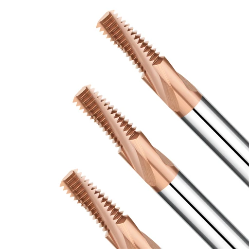

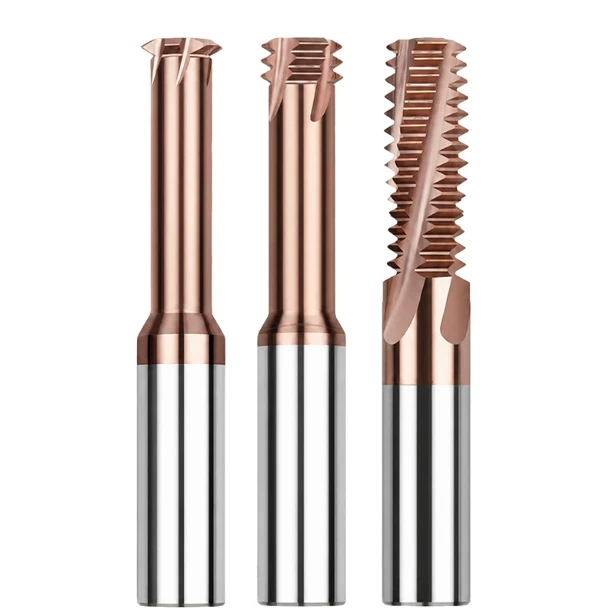
A European client making injection molds reached out with an urgent issue. While machining M6 internal threads in 1.2379 (D2) inserts hardened to 54 HRC, their shop ruined three consecutive carbide thread mills. Operators cut spindle speeds in half, doubling cycle times. Yet every removed tool showed chipped crests or delaminated coatings, and parts consistently failed thread gage inspection.
We encounter this scenario constantly while providing technical field support across North America and Europe. Machinists often treat hardened tool steels like standard pre-hardened or alloy steels. However, extreme yield strength and severe friction spike cutting zone temperatures instantly. In this environment, thread mill wear in hardened steel is rarely standard flank wear; it is premature failure driven by thermal shock, wrong chip clearances, or improper micro-geometry.
Every wear pattern on a cutting tooth tells an exact story of cutting force and thermal load. Blindly buying expensive coatings or dropping spindle speed only conceals root problems. In fact, cutting too slowly often accelerates tool breakdown through work hardening and rubbing.
Are your scrap cutters in deep hardened holes failing from thermal softening at high surface speeds? Or are ultra-light chip loads rubbing the edge to death in the cut?
Core Pain Points in Mold Steel Thread Milling: Common Failure Modes
Milling threads in steels over 50 HRC presents two massive roadblocks: abrasive carbide segregations and poor thermal conductivity. Thread milling is an interrupted cut. Each tooth engages the material for mere milliseconds, shearing metal with yield strengths over 1800 MPa before suddenly cooling upon exit. Operators making the mistake of expecting gradual tool wear usually watch a fresh cutter self-destruct after two holes.
Our lab has examined hundreds of failed cutters under high-power optical microscopes. Failures in mold steel thread milling follow clear, repeatable mechanics rather than smooth, predictable flank loss. High contact stresses trigger micro-cracks that multiply within seconds. Catching these early failure signatures allows you to fine-tune toolpaths and speeds before scrap parts hit the bin.
H3: Initial Edge Chipping and Mechanical Spalling: Thread Mill Cutting Edge Wear
If your “go” thread plug gage suddenly binds or tooth crests show ragged nicks, you are facing micro-chipping. We recently inspected a high-hardness stamping die run in an Ohio machine shop where tool life fluctuated wildly. Microscopic inspection revealed no classic flank wear bands, but rather scalloped, brittle fractures along the primary relief. This severe thread mill cutting edge wear stems directly from heavy entry impact shock.
Curing this fracture mode starts with checking tool entry strategies and micro-geometry. Machinists often assume razor-sharp edges cut with less resistance, but ultra-sharp edges snap under high hardness. Applying a controlled 0.010 mm to 0.015 mm edge hone and switching from linear plunges to a 180-degree roll-in arc spreads engagement forces and prevents mechanical edge tear-out.
Abrasive Wear and Thermal Fatigue Cracking: Thread Mill Wear Mechanism in HRC 50+
Quenched cold-work steels contain high-hardness primary alloy carbides that out-scrape the softer cobalt matrix of a tool. As the cutter sweeps through the cut at thousands of RPM, these microscopic hard points plow distinct longitudinal grooves across the tool flank. At the same time, rapid heating and cooling cycles create intense thermal fatigue. This dual thread mill wear mechanism forms comb cracks along the cutting edge, leading to catastrophic tooth loss.
Managing this wear pattern requires a critical decision on coolants. Flooding the cut with water-soluble emulsion triggers violent thermal shock during interrupted milling, rapidly accelerating thermal fracture networks. Our cutting data proves that switching to dry compressed air or Minimum Quantity Lubrication (MQL) clears chips reliably, moderates thermal shock, and significantly extends usable tool life.
Nanocomposite Coating Delamination and Oxidation: Thread Mill Coating Wear
Coatings are your substrate’s only defense against high-temperature diffusion. When you pull a thread mill from the toolholder and see the violet-gray coating turned dull gray—or exposed raw carbide—the coating barrier has broken down. In deep blind holes, typical thread mill coating wear occurs when localized shear interface temperatures exceed the coating oxidation limit, which sits around 900°C to 1100°C.
Upgrading to a higher-rated coating alone will not fix premature flaking. If substrate hardness does not match coating internal stress, or edge preparation is skipped, the film simply shears off under heavy loads. Pair thick AlTiN or nanocomposite AlTiSiN layers with proper substrate surface preparation, and regulate cutting speeds to stop friction heat from melting your protective barrier.
Mismatched Cutting Parameters: Tracing the Root Causes of Thread Mill Wear
When inspecting a burned-out cutter, never blame carbide grain quality or sintering batches first. Instead, pull the CNC program and audit the baseline cutting parameters. Hardened tool steels offer razor-thin margins for error due to extreme shear resistance and poor elasticity. An operator tweaking the feed override dial by just 15% can instantly shatter cutting force equilibrium.
During field troubleshooting, our team runs reverse calculations on spindle load, peripheral surface speed, and programmed tooth advance. Our diagnostic data confirms that bad parameter pairings drive over 60% of premature thread mill wear causes. Surface speed, chip load per tooth, and radial stepover are codependent factors that dictate cutting zone heat and mechanical stress.
Thermal Softening from Excessive Speed: Thread Milling Cutting Speed Limits
Programmers often overlook the speed delta between centerline path feed and true tool-tip peripheral speed inside small bores. In one 55 HRC mold cavity job, a shop boosted peripheral speed to 90 m/min to shave cycle seconds. The cutter dulling was severe by hole three. Since hardened steel cannot dissipate heat, localized friction rapidly degraded the cobalt binder, causing plastic deformation at the cutting edge.
Empirical testing dictates a disciplined, conservative approach to thread milling cutting speed in hardened stock. For 50 to 56 HRC steels, keep peripheral speed strictly within 45 to 65 m/min; drop to 35 to 45 m/min past 58 HRC. Trading two extra seconds per hole keeps interface heat below the coating’s oxidation ceiling, preventing thermal collapse and rapid catastrophic chipping.
Burnishing from Light Feeds: The Direct Impact of Feed Per Tooth on Thread Wear
Fearing instant breakage, operators often drop feed rates to crawl speeds, mistakenly thinking lighter means safer. On hardened workpieces, this is disastrous. Under toolroom microscopes, we frequently find mirror-like flank burnishing and micro-tearing caused by running chip loads under 0.005 mm per tooth. Because typical edge preparation hones fall between 0.008 and 0.012 mm, ultra-light feeds fail to shear metal cleanly.
Instead of cutting, the tool tip rubs, generating severe work hardening on the hole walls. This secondary hardened glaze accelerates friction and causes extreme thread wear. Always choose moderate mechanical shear load over rubbing. Maintain an effective feed per tooth between 0.015 and 0.035 mm so the edge bites past the work-hardened zone and pulls away clean micro-chips.
Radial Depth and Multi-Pass Paths: Preventing Thread Mill Wear in Hardened Steel
Forcing a full-profile or single-point thread mill to cut full thread depth in a single pass invites immediate failure. While auditing a European auto parts supplier suffering high scrap rates, we found their macro cutting the full 60-degree V-profile in one go. The huge instantaneous contact arc produced massive radial spikes, causing tool deflection and chatter deep inside the hole.
Single-pass overloading remains a primary trigger of thread mill wear in hardened steel. We eliminate this by splitting radial cut depth across 2 to 4 helical passes: 60% stock removal on pass one, 30% on pass two, and a 0.02 to 0.04 mm light spring pass. This distributes tooth stress, eliminates half-angle thread taper, and protects fragile crest tips.
Toolholders, Clamping, and Rigidity Control: The Overlooked Drivers of Thread Milling Tool Wear
Shop engineers often fixate on speeds and feeds while ignoring the rigid clamping chain from spindle taper to collet and workpiece. Interrupted milling in high-hardness stock generates violent high-frequency impact waves that travel upward through the toolholder. Any micro-clearance or deflection in the toolholder instantly ruins uniform tooth load sharing.
Assuming shallow thread milling cuts permit aging spring collets or loose holders is a costly mistake. Our technical audits confirm that dynamic chatter and holder flex cause subtle, destructive thread milling tool wear. Deflection induces micro-vibrations that distort thread pitch and rapidly wear cutting edges, regardless of how well parameters are programmed.
Overhang and Dynamic Runout: How TIR Amplifies Thread Wear
We frequently put dial indicators on tool setups where operators run long-reach necked cutters past 4xD stickout with runout topping 0.008 mm. With chip loads measuring only a few microns per tooth, dynamic runout exceeding 0.005 mm means one single tooth absorbs over 70% of the entire cutting load. The remaining teeth merely rub the workpiece surface.
This severe load imbalance subjects the highest tooth to destructive impact spikes, inducing fast micro-chipping and flank spalling. We advise replacing extended ER collet chucks with rigid hydraulic chucks or shrink-fit toolholders, keeping stickout under 3xD. Holding dynamic runout under 0.003 mm at the tip ensures even load distribution and stops abnormal thread wear.
Climb Milling and Entry Strategy: Roll-In Arcs to Protect Thread Mill Cutting Edge Wear
Linear, straight-line plunges into sidewalls generate heavy impact shock when entering steels past 50 HRC. Hitting hardened walls at a 90-degree angle behaves like striking hardened tool steel with a hammer. Tool vibration spikes immediately, and cutting teeth often chip or tear along the rake face before completing their very first helical revolution.
We mandate climb milling paired with a 90-to-180-degree roll-in helical arc entry. Smooth entry transitions chip thickness from thick to thin, eliminating sudden load spikes during initial tooth engagement. This gentle path shields vulnerable crests, curbs premature thread mill cutting edge wear, and ensures the tool enters the cut under stable, controlled mechanical strain.
Chip Evacuation and Thermal Shock: Balancing Coolant Methods for Thread Mill Tool Life
In blind holes, unevacuated chips spell disaster. Hardened micro-chips that fail to evacuate drop back into the path of rotating flutes, where they undergo secondary crushing. Cutting edges forced to regrind hardened swarf wear twice as fast as normal and face high risks of sudden tool snapping.
Coolant selection requires a calculated compromise between chip evacuation and thermal cycling. Flooding 52+ HRC steel with water-based coolant induces severe thermal shock during interrupted cuts, triggering comb cracks. We recommend dry compressed air at 6 bar minimum, or Minimum Quantity Lubrication (MQL) with high-pressure air blast, to eject chips safely and extend overall thread mill tool life.
A Root-Cause Solution for Hardened Steel: Custom Carbide Thread Mills and Parameter Compensation
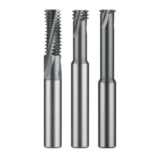
If you already dialed back surface speed, added stepover passes, and eliminated holder runout, yet tools still chip in 55+ HRC steel, standard catalog cutters are failing you. Off-the-shelf tools are compromises built to handle everything from mild steel to aluminum. Their positive rake faces and uniform flute spacing simply lack the web strength required to resist high lateral deflection forces in hardened alloys.
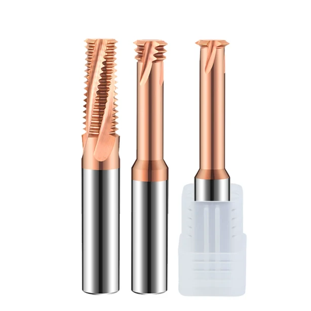
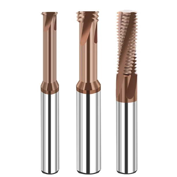
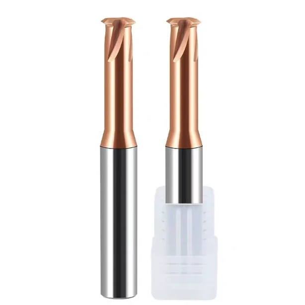
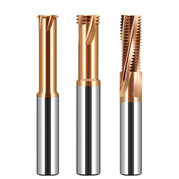
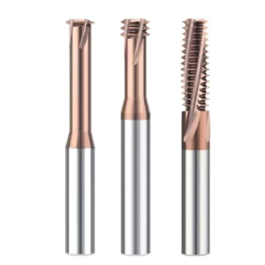
When troubleshooting complex holes for European and American manufacturers, our long-term answer is purpose-built tooling. A high-performance custom carbide thread mill is not just standard carbide with an expensive purple coat. We re-engineer the tool from the raw grain matrix and core thickness to the microscopic edge prep, eliminating deflection and stabilizing thread pitch across high-volume production.
Sub-Micron Carbide Substrates and Honing: Halting Thread Mill Wear in Hardened Steel
Machining tool steel demands a delicate balance between core toughness and edge hardness. Picking a hard carbide grade above 94 HRA often backfires; low cobalt content makes teeth brittle under shock loads. For 50 to 62 HRC dies, we specify sub-micron carbide with 0.4 to 0.6 μm grain sizes and 10% to 12% cobalt. This matrix delivers the flexural strength needed to absorb heavy shear spikes.
Edge preparation determines tool survivability. Under an electron microscope, ground-raw edges show serrations and grinding micro-cracks that snap within milliseconds of contact. We apply micro-blasting or precision nylon brushing to hone a uniform 8 to 15 μm edge radius with a tiny negative T-land. This geometry prevents stress peaks, stopping the brittle fractures driving thread mill wear in hardened steel.
Negative Rakes and Unequal Flute Pitch: Mitigating Thread Mill Wear and Chatter
Cutting hardened tool steel requires sacrificing “free-cutting” sharpness for raw edge support. We grind a 3 to 6-degree negative radial rake backed by reinforced secondary clearances. Negative geometry pushes cutting forces back toward the tool centerline, putting the tooth crest under compression rather than tensile strain. While thrust demands increase, chipping stops cold.
Deep-hole threading also faces harmonic chatter. We break self-excited resonance by combining variable helix angles with unequal flute spacing. Disrupted tooth engagement intervals eliminate harmonic spikes before vibration can build. In deep mold cavities, this asymmetric damping kills side deflection, smoothing tool paths to reduce severe thread mill wear and boost reliable tool life.
On-Site Radial Compensation: Predicting Thread Mill Tool Life with Gaging Feedback
Dynamic CNC tool wear offsets provide your last line of defense for thread quality. Never wait until a “go” gage binds or a “no-go” gage rattles to react, because the tool has already begun burning the thread crests. We set step-wise macro offsets based on batch sampling, compensating 0.003 to 0.005 mm on diameter after fixed hole counts to counter abrasive wear.
More importantly, tie tool life directly to gage tactile resistance. Train operators to pull the cutter the moment the “go” gage requires firm finger pressure to seat, rather than waiting for it to jam. Retiring the cutter at this wear inflection point prevents tool breakage in valuable mold cavities and provides predictable data to extend overall thread mill tool life.