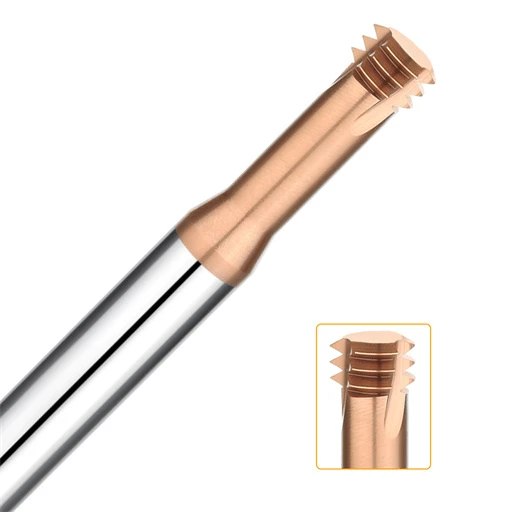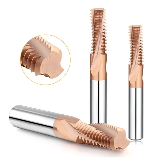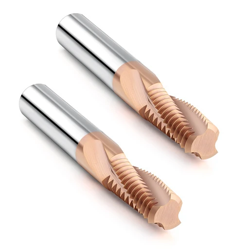


This scenario unfolded on our shop floor during a technical call with a German mold manufacturer. The job ran an SKD11 slide insert heat-treated to a measured HRC65 with M6×1.0 blind holes. The operator tore through three brand-new carbide thread mills in a row; none made it past hole eight. Under our 200x bench microscope, we found massive rake-face chipping and coating micro-cracks instead of normal flank wear. The shop was burning through premium tooling like cheap throwaway inserts.
This is a recurring crisis our field team handles across US and European facilities. Hardened mold steels (HRC60–65) turn thread milling into an aggressive test of mechanical impact and heat. Many machinists instinctively drop their spindle speeds or order specialized coatings to combat thread mill wear. That usually backfires: dropping speed causes edge burnishing, while heavy chip loads fracture the brittle carbide.
To curb hardened steel thread mill wear and boost tool life, you need a balanced process rather than isolated patches. That means micro-honed negative rakes, heat-resistant nanocomposite coatings, and sub-0.003 mm tool holding. Most importantly, it requires abandoning straight plunges for roll-in arc paths and multi-pass profiling.
If your VMC constantly breaks cutters or thread gauges jam after twelve parts, pause your cycle. Is the cutter really wearing out—or is that harsh linear entry breaking your teeth on impact?

Analyzing Thread Mill Wear in Hardened Steel: Identifying Causes and Failure Modes
Do not toss a broken cutter and blindly hit cycle start with a new one. Inspect the cutting edges under a pocket loupe or microscope first. Cutting material past HRC62 generates interface temperatures and mechanical stresses that destroy edges rapidly. Operators often blame the tool supplier for every failure. You must distinguish thermal spalling from mechanical impact damage; otherwise, path offsets and wear compensations remain pure guesswork.
Failure analysis in hard milling is straightforward reverse engineering. Every scratch, white band, or chipped tooth reveals a specific path error or machine setup flaw. In our field troubleshooting, catching these micro-wear markers early preserves carbide tools. It is also the only reliable way to pinpoint root thread mill wear causes during long-run production on hardened mold inserts.
Distinguishing Between Crater Wear and Micro-Chipping: On-Shop-Floor Diagnosis
You must separate crater erosion from edge chipping immediately. Crater wear happens on the rake face via chemical diffusion and chip wash, appearing slightly behind the cutting edge. Chipping happens when brittle micro-grain carbide fractures under interrupted mechanical shock. If your fingernail catches on a jagged, sawtooth edge, you are dealing with chipping rather than standard abrasive wear.
We treat this difference as a clear operational trade-off. Rake crater wear is often a workable condition, provided it stays behind your edge prep. A chipped edge as small as 0.02 mm causes cutting resistance to spike immediately. That localized force snaps the entire cutting flute within two pitches. When tackling severe thread mill wear, smooth out your entry interpolation instead of arbitrarily slashing surface footage.
Investigating the Root Causes of Abnormal Flank Wear in Thread Milling SKD11
Machining deep-hardened tool steel often generates aggressive flank wear bands far faster than expected. During SKD11 thread milling, shiny and uneven wear scars are rarely caused by high spindle speed alone. They stem from ultra-hard eutectic carbides exceeding HRC70 embedded within the steel matrix. As cutting forces deflect the tool slightly, flank clearance closes, turning those trapped carbide particles into abrasive grinding media.
We check two main culprits during on-site reviews: pre-hole drill quality and tool overhang ratios. The problem is rarely a lack of carbide red hardness. Dull drills leave a severe work-hardened skin on the pilot hole walls. Excessive overhang flexes the tool, causing teeth to slide against the wall rather than shear the stock. That micro-rubbing destroys tool clearance and jams thread gauges within five holes.
Why Do Coatings Peel Prematurely? The Impact of Substrate Hardness and Thermal Shock on Thread Mill Wear in Hardened Steel
When cutting ultra-hard metals, coatings rarely wear down smoothly; they flake off in sheets. Understanding this specific hardened steel thread mill wear requires viewing the coating and carbide substrate as an interconnected system under load. Nanocomposite coatings offer exceptional hot hardness, but contact zone friction easily tops 800°C. If the underlying carbide lacks compressive yield strength, it deforms microscopically, popping the thin, brittle shell right off.
Thermal shock from coolants is even more destructive. Machinists often run flooded emulsion to suppress heat, but interrupted cutting creates brutal 1,000°C-to-ambient thermal cycling. This expansion stress fractures the coating-to-substrate boundary with transverse thermal cracks. Unless blind-hole chip evacuation strictly demands liquid pressure, switch to dry cold air or micro-lubrication (MQL) to prevent thermal spalling.

Tool Body Selection and Geometric Design: Optimization Strategies for Thread Milling Tools in Ultra-Hard Material Machining
At HRC65, microscopic tool flaws trigger massive failures under cutting pressure. General-purpose cutters shatter the second they touch high-hardness mold steel. Surviving ultra-hard metals takes far more than just picking a harder carbide blank. You must align the tool core rigidity, cutting edge prep, and thin-film coating properties simultaneously.
Every grind choice involves an engineering trade-off. Sharp edges chip on hard carbides, while heavy hones generate extreme interface heat. Thick cores boost bending strength but restrict chip flow, risking destructive chip packing. Selecting dedicated thread milling tools remains the single most reliable way to secure consistent tool life before cycling your machine.
Prioritizing Rigidity: How Short-Flute, Necked Designs and Left-Hand Helix/Right-Hand Cut Geometries Suppress Runout in Thread End Mills
Running long-flute cutters in deep blind holes is a recipe for broken tooling. We mandate short-flute designs with necked relief shanks for deep hole threading. Restricting cutting teeth to two or three pitches shortens the bending moment arm under load. This simple change removes high radial thrust, allowing your thread end mill to cut without catastrophic deflection.
Spindle rigidity also dictates flute direction. We frequently switch to a left-hand helix with right-hand rotation on lighter machines. This setup converts downward pulling forces into an upward thrust against the spindle taper. The tool seats firmly in the holder, eliminating chatter during helical interpolation, provided shop air clears the downward chip flow.
Negative Rake Angle Combined with a Micro-Chamfer (T-Land): Flute Geometry to Enhance Impact Resistance in CNC Thread Milling Bits
Positive rake angles fail completely once steel hardness passes HRC60. Our tool grinding tests show a radial negative rake of -5° to -10° is essential. This negative geometry directs resultant cutting forces into the solid core of the tool. It trades destructive tensile tearing for compressive shear, keeping brittle micro-grain carbide intact during interrupted cuts.
A negative rake still requires a precision micro-chamfer (T-land) on the cutting edge. When grinding a high-performance cnc thread milling bit, we apply a 0.015 to 0.03 mm wide land at a 15° angle. A micro-honing polish then cleans away grinding burrs. This composite edge spreads initial chip impact evenly across the radius, preventing hard carbides from breaking tooth tips.
Controlling Coating Thickness for Nanocomposite Coatings to Resist Wear in HRC65 Thread Milling
Thicker coatings do not guarantee longer tool life in hardened steel milling. Heavy films trap residual tensile stress and dull precisely honed cutting edges. Thick coatings also spall off under high mechanical shock, ripping underlying carbide away with them. We strictly cap total thin-film deposition between 1.5 and 2.5 microns for these severe setups.
Silicon-doped nanocomposite coatings like AlTiSiN excel in extreme heat. Cutting zone temperatures routinely pass 900°C, triggering silicon to form a self-healing amorphous silica barrier. This shield blocks thermal oxidation and insulates the cutting substrate. Tight coating thickness combined with high adhesion stops flank abrasion, directly preventing premature HRC65 thread mill wear.

Beyond Textbook Formulas: Practical Thread Milling Speeds, Feeds, and Toolpaths
Standard machining handbook formulas fail miserably in HRC65 blind holes. Programmers calculating feeds directly from generic software charts end up with melted edges or snapped cutters within seconds. Cutting ultra-hard materials requires balancing localized shear heat against edge impact limits. You cannot treat hardened tool steel like standard pre-hardened alloys.
Field-tested machining parameters require a flexible operating window rather than fixed charts. You must recalculate feeds from tool centerline paths to actual peripheral contact, and skip single-pass strategies. Establishing and adhering to disciplined thread milling speeds and feeds turns unpredictable threading runs into a repeatable, stable shop process.
Managing Cutting Speed: Staying Below the Thermal Accumulation Threshold
Running excessive surface footage in quenched steel guarantees rapid failure. Cold-work steels and powder metallurgy alloys conduct heat poorly, trapping intense friction right at the cutting tooth. In our field tests, pushing past 50 m/min softens coating interfaces and prompts plastic deformation on the rake face.
We keep cutting speed locked between 25 and 45 m/min to protect the carbide substrate. Small-diameter internal threads still require strict speed caps despite high spindle capabilities. Limiting heat generation to match tool dissipation rates stops runaway thermal breakdown, providing our first line of defense against severe hardened steel thread mill wear.
Feed per Tooth (fz) and Radial Depth of Cut (ae): Multipass Strategies to Prevent Tool Chipping
Feed per tooth requires careful calibration. Dropping feed below 0.003 mm causes cutting edges to rub and work-harden the hole wall instead of shearing metal. Conversely, heavy feeds cause carbide teeth to fracture on hard inclusions. We maintain effective feed between 0.008 and 0.02 mm per tooth to stay above the minimum chip-shearing threshold.
To run healthy chip loads safely, divide radial cut depth (ae) across multiple passes. Never cut HRC65 threads in one heavy pass. We program three stages: 60% depth on the roughing cut, 30% on the semi-finish pass, and a 10% skim cut (0.02–0.05 mm) to correct tool deflection. This staged approach lowers bending loads and prevents edge chipping completely.
Abandoning Linear Entry: The Tangible Benefits of Arc-in (Roll-in) Approaches for Extending Thread Mill Tool Life
Linear radial entries directly into the hole wall spike tool failure rates. Driving the cutter straight into the stock creates an aggressive 90° entry shock. This sudden impact acts like a hammer strike against brittle carbide teeth, creating invisible micro-fissures across the rake face before normal milling even begins.
We program a 90° or 180° tangential roll-in arc path on all hardened parts. Ramping smoothly along an arc thickens chips gradually, building cutting forces linearly. The tool exits along a matching tangential path with zero dwell marks. Adopting smooth circular engagement eliminates shock loads, providing an immediate boost to your overall thread mill tool life.
Cooling Methods and Machine Tool Dynamic Rigidity: Key Process Details for Extending Thread Mill Tool Life
Machinists often focus solely on tool geometry while ignoring machine rigidity and cooling. Over 30% of premature tool failures stem from clamping vibration or thermal shock. At HRC65, microscopic oscillations of just a few microns break cutting edges. Temperature spikes in tight blind holes quickly ruin an otherwise ideal edge prep.
Spindle rigidity and chip evacuation are the true foundation of thread milling stability. Clamping flex or poor heat extraction will defeat the best carbide substrate available. Cleaning up your cooling setup and improving tool assembly balance delivers immediate results. This approach maximizes cutting efficiency and extends overall thread mill tool life without requiring costlier tool grades.
Avoid Liquid Coolant: The Benefits of MQL and High-Pressure Cold Air in Preventing Cracking During Thread Milling at HRC65
Blasting water-soluble coolant into small holes invites thermal stress cracking. Under our inspection scopes, failed cutters routinely show comb-like thermal fractures across the cutting edges. High-speed contact heats the teeth to near 1,000°C before cold coolant quenches them mid-rotation. This cyclic thermal shock tears the protective thin-film coating right off the substrate.
We eliminate flood coolant entirely during HRC65 thread mill operations. We rely on Minimum Quantity Lubrication (MQL) paired with a sub-zero vortex air blast. Micro-droplets reduce contact friction, while dry high-pressure air sweeps fine abrasive chips out of blind hole roots. Maintaining a stable, dry cutting zone prevents thermal fatigue and eliminates catastrophic tooth spalling.
Controlling Tool Runout to Within 0.003 mm: The Critical Role of Hydraulic and Shrink-Fit Tool Holders in Mitigating Thread Mill Wear on Hardened Steel
A 0.01 mm runout might pass in mild steel, but it destroys cutters in hardened stock. Excessive runout concentrates the entire cutting load onto a single high tooth during interpolation. That overloaded tooth fractures instantly, forcing remaining flutes to absorb unbalanced impacts until the tool snaps. We keep total radial runout under 0.003 mm on every machine setup.
We replace standard ER collet chucks with hydraulic holders or short-overhang shrink-fit systems. Hydraulic holders dampen high-frequency harmonics, while shrink-fit units deliver high concentric clamping force. Balancing the chip load evenly across all flutes stops irregular wear patterns. This strict balance prevents premature hardened steel thread mill wear and keeps thread pitch diameters consistent.
Controlling Pilot Hole Tolerances and Work-Hardening: Preventing “Premature Failure” of Thread End Mills
Pilot hole quality is often the most overlooked landmine in hard milling. Worn pre-hole drills create excessive thrust, producing a work-hardened glaze along the hole walls. This glazed skin is significantly harder than the bulk workpiece material. Entering this hard skin spikes cutting torque instantly, destroying delicate cutting tips on the very first thread pitch.
We inspect drill wear closely to eliminate extrusion drilling before threading begins. We also bias pilot hole diameters toward the upper tolerance limit, targeting 60% to 70% thread engagement. Opening the hole slightly satisfies required pull-out strength while relieving intense edge stresses. This simple adjustment gives your thread end mill vital clearance to shear stock smoothly.
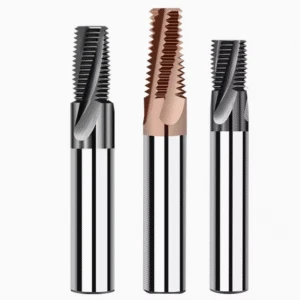
Case Study: How to Triple Thread Mill Tool Life When Machining M6 Threads in SKD11
Lab theory means nothing until parameters perform under actual spindle loads. Combining micro-chamfers, thin coatings, roll-in paths, and MQL creates an integrated cutting system. You rarely need new machine tools to solve chronic tool breakage. You only need a surgical, systematic cleanup of hidden setup oversights across your current production workflow.
Eliminating hole work-hardening, tightening spindle runout, and splitting cuts into multiple passes shields cutting teeth from impact spikes. Applying this methodology directly to heat-treated production parts reduces cutting tool expense substantially. More importantly, it creates repeatable consistency, delivering a proven, measurable boost in thread mill tool life across long production runs.
Troubleshooting a Bottleneck: A European Mold Manufacturer’s Experience with CNC Thread Milling Bits
A German precision mold shop struggled with M6 blind holes in SKD11 vacuum-hardened to HRC65. The depth was 12 mm. Machinists used ER20 collet chucks, long-flute cutters, straight radial plunge paths, and flood coolant. Every cnc thread milling bit chipped heavily by the eighth hole. Thread plug gauges seized mid-depth, forcing machine stoppages every thirty minutes.
Our on-site inspection uncovered three critical bottlenecks immediately. First, dial indicators revealed 0.012 mm of dynamic runout at the tool tip, overloading a single tooth. Second, flood coolant caused violent thermal shock, cracking the coating interface. Third, straight radial entry created massive torque spikes that shattered the carbide teeth. The entire process was destroying the tooling before real wear could occur.
Wear Comparison and Actual Tool Life Following the Transition to a Three-Pass Helical/Arc-Entry Strategy and Optimized Thread Milling Speeds and Feeds
We updated the setup with short-overhang shrink-fit holders, locking runout under 0.002 mm. We replaced flood coolant with 0.4 MPa dry cold air and vegetable-based MQL. Linear entries were scrapped for 180-degree roll-in arcs across three passes (55%, 35%, and 10%). Finally, we recalculated thread milling speeds and feeds, lowering cutting speed to 32 m/min with correct peripheral chip loads.
The results were immediate: tooth chipping vanished completely, replaced by smooth, even flank wear across all flutes. Tool life jumped from 8 holes to 28 holes per tool—more than a 3x increase—with a 100% thread gauge pass rate. If you face broken cutters in HRC60+ tool steels, inspect your runout, eliminate thermal dousing, and soften entry impact. Send us your workpiece material, hole tolerances, or cycle data, and we will help you dial in the numbers.