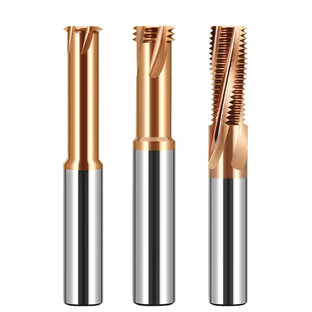

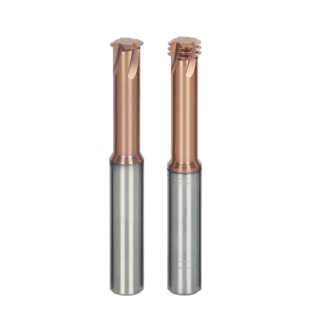
Few moments in a precision machine shop are more nerve-wracking than blind-hole tapping on a die worth tens of thousands of dollars. The workpiece has already absorbed significant capital through vacuum heat treatment, wire EDM, and precision surface grinding. One minor mistake at this final stage scraps weeks of skilled labor and raw materials.
Consider a classic shop-floor scenario: a customer delivers stamping die inserts made from powder-metallurgy tool steel at HRC 63–65. The print specifies M4 and M6 threads deep inside tight counterbores. The machinist watches the spindle load spike before hearing the dreaded snap of a seized tap. Attempting to burn out the broken tool with an EDM disintegrates surrounding datum features and destroys critical tolerances.
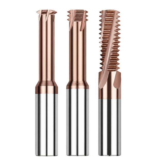
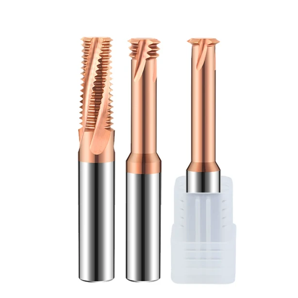
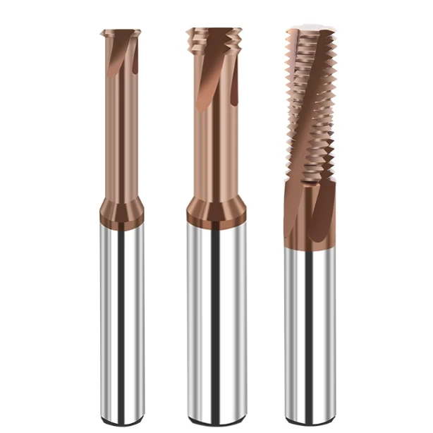
We see this exact disaster repeat itself across North American and European mold facilities. Many shops try to force conventional rigid tapping into their process by fine-tuning speeds and lubricants. However, shear yield strength climbs exponentially once steel surpasses HRC 60. The challenge shifts from evacuating chips to forming threads without catastrophic impact loads. That is why our field engineering team exclusively specifies an HRC65 thread mill for post-hardening operations.
Achieving true thread precision in high-hardness materials requires more than grabbing an off-the-shelf end mill. Prototyping and cutting tests prove that the best carbide thread mill for hardened steel requires a delicate trifecta: ultra-fine sub-micron tungsten carbide, a high-adhesion nanocomposite PVD coating, and negative radial rakes with controlled hone radiuses. A tiny mismatch here causes tool deflection, pitch taper, or micro-chipping within three holes.
Would you risk a high-value mold core by running a process where a broken tap means an immediate scrap report? Or would you trust a controlled, multi-pass milling strategy that holds every pitch diameter dead-center within tolerance? If you manage this production cell, does saving thirty seconds on cycle time justify gambling the entire part?
Overcoming the Deadlock of Tapping Hardened Steel: Why Use a Thread Mill for HRC55–HRC65 Steel Instead of Forming or Cutting Taps?
Once core hardness crosses HRC 55, the physical margin of error for conventional taps drops to zero. Cold-forming taps demand plastic deformation, but hardened steel has zero ductility left to give. The resulting torque snaps tap shanks instantly, and intense dry friction friction-welds workpiece material to the tool crests.
Cutting taps do not fare much better under these extreme conditions. Full-contact tooth engagement spikes cutting torque well beyond what small-diameter tool bodies can support. That is why we transitioned our Tier-1 tooling accounts to a specialized thread mill for HRC55-HRC65 steel. Intermittent point contact slashes radial cutting forces to a fraction of tapping loads, eliminating catastrophic failure modes.
Machining Hardened D2, SKD11, and 1.2379 Dies: Real-World Lessons in Saving High-Tolerance Tooling
During a pre-production run for a progressive stamping die in Germany, the customer ran 1.2379 tool steel (D2/SKD11 equivalent) cryogenically treated to HRC 62. Racing to meet a delivery deadline, the programmer programmed an imported coated carbide tap into an M5 blind hole on a vertical machining center. Without audible warning, the tap snapped flush at the hole bottom.
The broken shank sat trapped next to guide-pin bores held to 5-micron positional tolerances. Sink-EDM removal would have caused thermal boundary damage and annealed the surrounding steel. We drove to the plant that evening and used an ultra-rigid carbide ball nose to interpolate out the tap core. We then deployed a multi-flute thread mill to clear the remaining pitch profile, proving to the shop that large-area continuous tool contact in high-carbon, high-chromium steels is an unnecessary gamble.
Thread Mill Cutting Accuracy Advantages: Eliminating Pilot Hole Expansion and Taper in HRC65 Stock
Machinists running hardened alloys often fight bell-mouthed hole entries, stripped lead threads, and severe taper. Traditional taps exert severe lateral pressures that expand pilot holes at the entrance while deflecting deeper into the cut. This creates an out-of-round hole where thread plug gages fail at the top and bind at the bottom.
Achieving consistent thread mill cutting accuracy comes down to controlling the direction of your cutting force vectors. We utilize radial multi-pass toolpaths paired with short-neck, thick-core tool bodies to constrain radial deflection. By programming standard tool radius compensation (G41/G42), operators can adjust pitch diameters down to the micron. For strict 4H or 6H aerospace and medical fits, this level of incremental dimensional control is unmatched.
Spindle Load Analysis: Rigid Tapping vs. Helical Milling with the Best Thread Milling Tool
We tracked continuous telemetry on a BT40 vertical machining center at an automotive tooling shop in Michigan running M8 threads in HRC 58 forged inserts. Rigid tapping consistently drove spindle motor torque to peaks of 75% to 85% during initial tooth entry and bottom-of-hole reversal. These repetitive torque spikes cause thermal growth in the spindle housing and accelerate wear on the Z-axis ballscrew bearings.
Switching that station to the best thread milling tool flattened the load monitoring charts immediately. The spindle runs at a constant, uninterrupted RPM while motor load stays between 18% and 25%. While helical interpolation might add two seconds per hole compared to tapping, it protects machine geometry and lets your operators run dark without their fingers hovering over the feed hold button.
A Deep Dive into Tool Substrates and Coatings: The Real Formula for a Long-Life Thread Mill
Machining parts past HRC 60 quickly exposes marketing hype. Many shops believe buying expensive micrograin carbide or applying a dark coating guarantees success. In reality, mismatched tools suffer catastrophic tooth fracture after just two holes. A reliable tool must balance micro-metallurgical grain bonding, PVD adhesion strength, and macroscopic internal stress relief.
During field trials, we prioritize the thermodynamic bond between core substrate toughness and coating thermal resistance. Engineering a true long tool life thread mill starts with strict powder purity in vacuum sintering. This process ensures the cutting edges withstand cyclic micro-impacts under extreme loads. Any shortcut during preparation leads to immediate tool failure once spindle speeds climb.
Grain Size and Cobalt Content: Why Ultra-Fine-Grained Substrates Power the Best Carbide Thread Mill for Hardened Steel
Substrate microstructure dictates total impact resistance in high-hardness milling. Increasing the cobalt binder phase improves flexural strength in soft alloys, but fails in HRC 65 stock. Excessive free cobalt softens rapidly under extreme cutting temperatures, losing its grip on carbide grains. Conversely, dropping cobalt too low creates brittle teeth that snap under alternating shear forces.
To solve this trade-off, we specify sub-micron carbide powders with grain sizes below 0.4 microns. We keep cobalt content strictly controlled within a narrow mass fraction window. This ultra-dense matrix shortens the mean free path, dissipating shear energy instantly. It forms the ultimate foundation for the best carbide thread mill for hardened steel, eliminating micro-pitting caused by grain pull-out.
Nanoscale Multilayer Coatings: Defeating 900°C Dry Friction Heat and Micro-Chipping
When an edge cuts hardened steel at high surface footage, localized contact temperatures easily surpass 900°C. Standard single-layer PVD coatings quickly suffer grain-boundary oxidation under such extreme heat. Thermal stress then triggers delamination at the coating-substrate interface, causing instant dulling and edge chipping.
Using advanced cathodic arc PVD, we deposit alternating nanolayers of aluminum-rich titanium and silicon compounds. This architecture forms an in-situ, self-healing oxide barrier of alumina and silica on the outer surface. It elevates oxidation thresholds past 1100°C, a staple feature of any high performance thread mill. The barrier blocks diffusion wear, ensuring cutting heat leaves with the evacuated chips.
Core Wall Thickness and Flute Geometry: Eliminating Tooth Breakage and Thermal Cracking
Geometry often matters just as much as premium metallurgy. To maximize chip clearance, some tooling designers grind deep, aggressive flutes. However, a thin core wall destroys dynamic rigidity in hardened steels. The resulting high-frequency micro-chatter shatters sharp thread crests and causes the tool to snap under radial load.
We re-engineered our flute proportions using a thick web core paired with an asymmetric variable helix. This configuration provides outstanding torsional stiffness and dampens harmonic vibration. In addition, mirror-polished flute valleys prevent hot chips from packing against the hole walls. Eliminating sharp interior corners stops thermal fatigue cracks from forming during rapid engagement cycles.

On-Site Parameter Tuning and Programming Pitfalls: Maximizing High Performance Thread Mill Potential
Premium tooling represents only half of the equation. When clients report premature wear or tool breakage, the issue is almost always in the CAM routine. Operators often copy macros meant for pre-hardened steels or run generic handbook feeds and speeds. In HRC 60+ tool steels, running theoretical numbers leads to immediate tool failure.
Success depends on synchronizing machine kinematics with cutting-edge engagement angles. Truly mastering a high performance thread mill requires tuning machine acceleration filters, low-end spindle torque, and radial chip thinning. The most reliable cutting parameters often seem counterintuitive on paper, but they are proven across thousands of real production runs.
Radial Multi-Pass Strategies: Setting ae and fz Limits for Thread Mill for HRC55-HRC65 Steel
Never cut full thread profiles in a single pass at HRC 65. Full-profile engagement creates crushing shear forces that instantly break delicate tool crests. We standardize on a two-to-three-pass radial strategy to balance tool life with cycle time. Take 50% to 60% of thread depth on the roughing pass, followed by decreasing radial passes (ae) and a final 0.02 mm spring pass.
Machinists often feed too slow out of caution, causing the tool to rub and work-harden the cut. Others feed too hard and chip the edges. For our dedicated thread mill for HRC55-HRC65 steel, we recommend 25–40 m/min surface speeds paired with 0.01–0.025 mm/tooth chiploads. Sacrificing a few seconds of cycle time prevents violent tool impacts against hard carbides.
Climb Milling Arc Entry and Exit: Protecting Thread Mill Cutting Accuracy Against Entry Shock
Linear, straight-line plunging into hardened hole walls spikes engagement angles from zero to maximum instantly. This shock wave travels straight through the toolholder into the spindle, triggering micro-fractures along the cutting edge. To eliminate this impact, we mandate a minimum 90-degree helical roll-in and roll-out arc path in all programs.
A tangential climb-milling entry ensures chip thickness starts thick and thins out smoothly at the exit point. This gradual load ramp protects sharp edges and delivers unmatched thread mill cutting accuracy. When finishing the full thread pitch, never dwell or retract linearly. Exit along a smooth tangential vector to eliminate witness marks, burrs, and stress risers.
MQL and Dry Air Blasting: Why Flood Coolant Accelerates Thermal Fatigue in HRC65 Stock
Drenching hot carbide in high-pressure water-soluble coolant is standard practice, but it ruins tools in hardened steel. In interrupted milling, the cutting edge experiences intense heat spikes followed by ice-cold liquid quenching thousands of times per minute. This violent shock network creates craze cracking along the coating, leading to sudden edge failure.
We advocate for high-pressure dry air or MQL setups instead. Compressed air provides dynamic pressure to eject abrasive powder chips from blind holes, preventing re-cutting. Meanwhile, microscopic vegetable oil droplets lubricate the rake face to reduce friction without quenching the edge. This dry approach keeps cutting temperatures stable, unlocking the full potential of a long tool life thread mill.
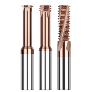
Real-World Procurement Considerations for B2B: ROI Analysis of Carbide Thread Mills and Tools for HRC65 Materials
When tooling requests hit the accounting desk, unit price is usually the only figure finance examines. In high-hardness machining, this narrow view creates an expensive blind spot. A cheap cutter that loses pitch tolerance after two holes carries massive hidden expenses. Downtime, scrapped workpieces, and tool reset hours quickly wipe out any upfront savings.
We urge shop managers to evaluate the real return on investment rather than the sticker price. True control of carbide thread mill cost balances substrate rigidity, PVD coating life, and amortized cost per hole. If a premium cutter runs reliably during unmonitored night shifts without snapping, it delivers substantial, measurable savings across the entire job.
Deconstructing HRC65 Thread Mill Price: Premium Brands vs. Actual Cost-Per-Thread
Many procurement teams default to tier-one European or Japanese brands, where small thread mills easily exceed several hundred dollars each. While these established brands offer consistent quality, their pricing includes heavy markups for brand premiums and multi-tiered overseas distribution. On high-volume runs in hardened alloys, an inflated HRC65 thread mill price quickly consumes a shop’s margins.
The practical way to assess tooling value is calculating cost-per-thread under identical machine setups. We factor effective cutting flutes, total threaded holes per tool, and tool replacement cost into one benchmark equation. If a custom solution matches 85% to 95% of an elite brand’s tool life at half the purchase price, your net margin increases substantially.
Mold/Die Scrap Costs vs. Carbide Thread Mill Cost: A Critical Technical Calculation for Western Clients
Threading usually happens as the final step on progressive dies, plastic injection molds, or aerospace blocks. By that point, the component has consumed roughing, heat treat, finish grinding, and wire EDM hours. The blank is often worth tens of thousands of dollars before cutting the first internal thread. Gambling that investment on an unproven cutter creates unacceptable financial exposure.
When consulting for North American and European die shops, we prioritize risk elimination above all else. In this context, calculating total carbide thread mill cost is equivalent to buying part-protection insurance. Spending slightly more on a dedicated hard-milling tool avoids hours of sinker-EDM spark extraction, protecting heat-treated core properties and locking in high first-pass yields.
Tool Life Inflection Points in Batch Machining: Defining Precise Tool-Change Protocols
Pushing an end mill until teeth fracture is a reckless way to chase savings in hardened steel. In stock over HRC 60, tool wear accelerates rapidly rather than progressing linearly. Once friction strips the outer PVD barrier, cutting heat spikes instantly. Radial forces jump immediately after, shoving the tool past its safe working limit within just a few cuts.
To hold tight gage tolerances, we establish strict, cycle-based tool retirement limits rather than relying on an operator’s ears. On high-value components, retire each high performance thread mill after hitting 80% to 85% of its proven lifespan. You can then downgrade the tool to rougher, non-critical setups while preventing sudden out-of-spec pitch diameters on your finish line.
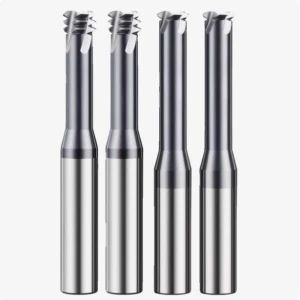
Engineer’s Procurement Guide: Practical Considerations for HRC65 Thread Mills and Custom Tooling
Selecting tools for hardened steel differs sharply from shopping for standard aluminum or mild-steel cutters. Any mismatch in tool overhang, tooth profile, or chip evacuation will ruin the advantages of premium carbide. When you cut stock at HRC 60+, small setup errors compound instantly.
This practical HRC65 thread mill buying guide compiles insights gathered across hundreds of field trials. Every shop runs distinct spindle tapers, shrink-fit holders, and part clamping configurations. Review your machine’s dynamic rigidity and target thread depth against the criteria below before issuing purchase orders.
HRC65 Thread Mill Selection Checklist: Tooth Profiles, Length-to-Diameter Ratios, and Air-Blast Channels
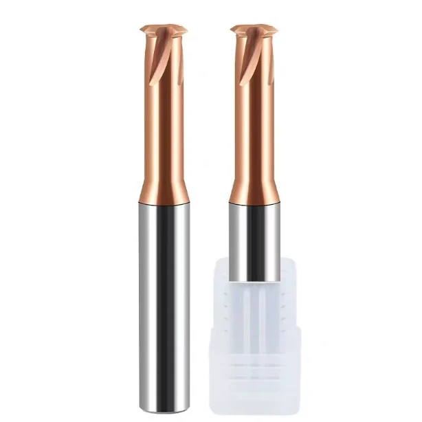
Tooth geometry directly governs radial cutting forces during helical interpolation. If you are milling deep blind holes or running a light-duty spindle, choose single-tooth or three-tooth cutters to minimize contact area and deflection. If you are running high-volume, shallow threads on a rigid 50-taper machine, choose full-profile tools to slash cycle times while keeping reach under 2.5D.
Clearance channels demand just as much attention as flute geometry. Without directed air clearing, fine abrasive powder stays trapped in the hole, grinding against the flutes. When selecting the best thread milling tool, confirm the coolant or air ports blast directly at the cutting interface. High-pressure dry air must eject chips upward instantly to stop chip packing.
Customizing Non-Standard Tolerances as an OEM Carbide Thread Mill Manufacturer
Standard 6H catalog cutters handle standard jobs, but aerospace, medical, and defense parts often require tighter pitch classes. Post-quench residual stresses and material elasticity frequently cause finished holes to fail pitch inspection. Off-the-shelf tools rarely resolve these unpredictable spring-back variations.
As a dedicated OEM carbide thread mill manufacturer, we adjust 5-axis CNC grinding wheel paths to offset specific material spring-back behaviors. If you are dealing with special pitch diameters, odd thread angles, or counterbore clearance problems, you can send us your part models. We adjust negative edge hones and neck reliefs to eliminate trial-and-error scrap on your floor.
International Delivery and On-Site Support: Remote Cutting Parameter Optimization and Rapid Prototyping
Sourcing custom tooling internationally often raises valid concerns about programming support and feeds-and-speeds verification. A custom cutter delivers zero value if unverified feeds cause it to chip immediately. We close this gap by auditing your specific machine dynamics and CAM toolpaths before shipping any custom tools.
We provide turn-key cutting parameters, safe entry vectors, and feed-reduction formulas tailored to your controller. If you are struggling with tap breakage in hardened tool steels or fighting inconsistent pitch gage fits, you can share your part prints, hardness data, and setup details with our engineers. We will analyze your cutting conditions and eliminate the risks before your spindle ever turns.