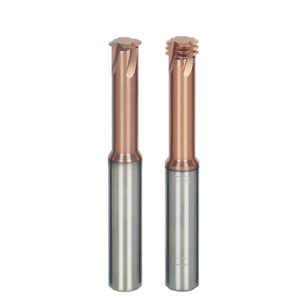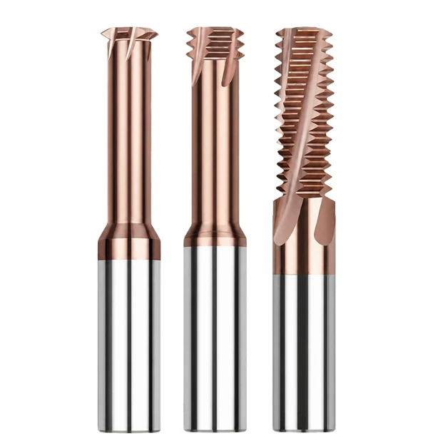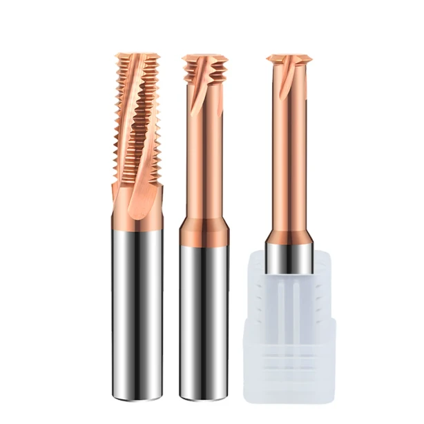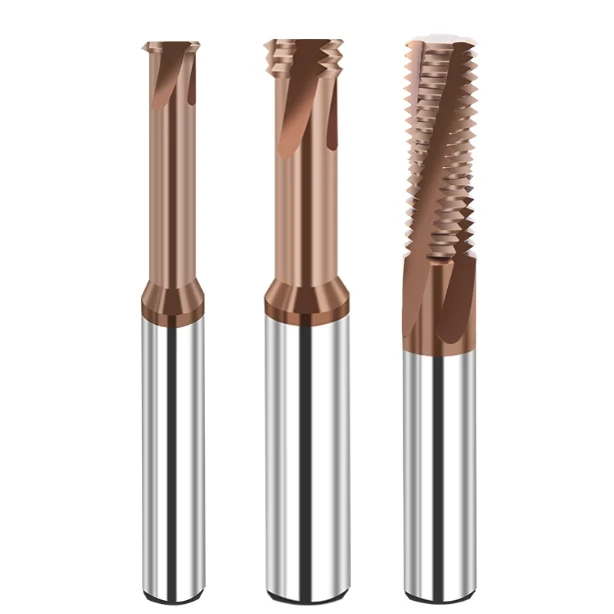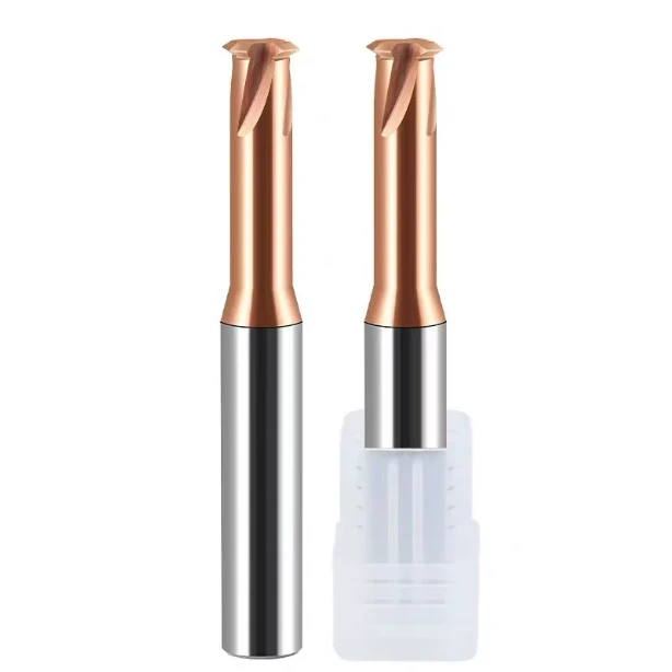

One of the most frustrating scenarios in any machine shop happens at the final stage of a high-value mold insert. The workpiece is already quenched to HRC65, carrying dozens of machining hours. An operator tries to drive a tap through, only for it to snap at the bottom of the hole. Another tries a standard carbide cutter, but the teeth chip after two rotations. This is not an isolated case; it is an ongoing issue we solve for precision mold shops across North America and Europe.
Extreme materials like fully hardened S136, D2, or SKD11 offer almost zero room for error. Traditional tapping leads to massive scrap rates, and burning broken tools out with EDM shatters lead times. In these setups, a dedicated HRC65 carbide thread mill with an ultra-fine sub-micron substrate and high-temp coating is the only reliable choice.
Whether cutting deep blind holes or holding tight Class 3B tolerances on UNC/UNF thread mills, every detail matters. Tool overhang, true chip load per tooth, and spindle torque limits directly dictate tool life and thread pitch accuracy.
When facing an expensive hardened workpiece with tight tolerances, has your shop truly dialed in the right toolpath and cutter geometry—or are you still gambling with a fragile cutting edge?
Mastering Hardened Components: The Core Substrate and Rigidity of Thread Mills for Heat-Treated Steel
When workpiece hardness exceeds HRC60, metal loses almost all capacity for plastic deformation. Cutting resistance and thermal spikes rise sharply in the cut zone. Many machine shops try cutting hardened tool steel using parameters meant for pre-hardened stock. The result is instant tool deflection, chatter, or catastrophic edge failure. Choosing a dedicated thread mill for heat-treated steel requires balancing carbide grain density with cross-sectional tool core strength.
If your spindle has high runout or long overhang, standard flute designs will flex. We design our cutters with a heavy core diameter to maximize static and dynamic rigidity. We use unequal helix angles to break harmonic chatter during entry. In HRC65 materials, microscopic tool deflection causes taper errors and pitch failure. Tool core rigidity must always take priority over wide chip evacuation flutes.
Solid Carbide Thread Milling Tools in HRC65 Mold Steels: Ultra-Fine-Grain Substrates
Machining HRC65 powder metallurgy or cold-work tool steels causes intense shear stress along the cutting edge. Standard 0.6-micron carbide grades develop micro-cracks along grain boundaries after just a few passes. Our shop tests show that solid carbide thread milling tools made from 0.2 to 0.4-micron sub-micron substrates handle this load best. Combined with an optimized cobalt binder, they provide the transverse rupture strength (TRS) needed to resist chipping.
Even sub-micron carbide cannot survive an improper edge prep. When operators report premature edge flaking, inspection under magnification usually reveals edge burrs or razor-sharp edges. We apply a controlled micro-hone or light negative T-land to the edge. This micro-prep adds 3% to 5% to radial cutting force, but it prevents micro-chipping. It keeps thread profiles stable across large production runs.
High-Temperature Dry Machining and Air-Cooling for Carbide Thread Cutter Longevity
Flooding the cut with water-soluble coolant is a common mistake when machining hard steels. Cold liquid hitting a 900°C cut zone causes severe thermal shock. This thermal cycling quickly generates spiderweb micro-cracks along the cutting edge. To maximize carbide thread cutter life, run dry with high-pressure air blast. Pair this setup with a heat-resistant AlTiN or nanocomposite coating rated past 1100°C so chips carry away the heat.
Flute geometry controls chip evacuation. Hardened steel produces short, brittle chips that must clear the hole immediately. We polish the flute surfaces to a mirror finish, reducing friction as chips slide up the tool. High-pressure air ejects the powdered chips without packing. If chips pack inside the hole, recutting will strip the coating and accelerate abrasive flank wear.
Controlling Radial Deflection with a Carbide Thread Mill for S136 Steel and D2/SKD11
Hardened stainless mold steels like S136 combine high tensile strength with abrasive hardness, while D2 and SKD11 pack large chromium carbides. Both generate heavy side forces during thread milling. The most frequent failure with a carbide thread mill for S136 steel is excessive radial deflection from single-pass cuts. This cuts a tapered hole—wide at the top and narrow at the bottom—causing the “Go” gauge to seize halfway down.
We recommend multiple radial passes using an equal-area material removal approach. Keep tool overhang (L/D ratio) below 2.5× whenever possible. For deep holes, switch from full-profile cutters to single-point tools to reduce the radial engagement arc. Taking three or four lighter passes takes slightly more cycle time, but it guarantees proper pitch diameter and prevents part scrap.

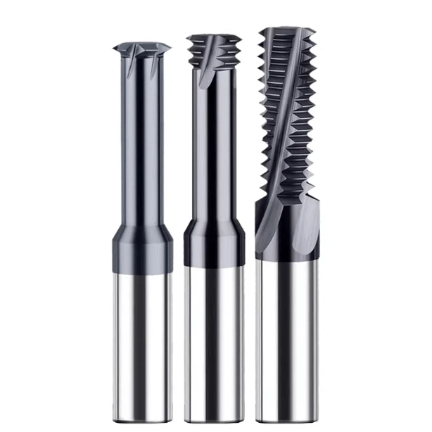
Practical Tool Selection: A Shop-Floor Comparison of Single-Tooth vs Full-Tooth Thread Mills
A classic dispute plays out on the shop floor: programmers push for multi-flute, full-form tools to slash cycle times, while machinists running hardened blocks report severe chatter and deflection. In our technical support across dozens of shops, neither design wins outright. The choice comes down to balancing radial engagement area against side-cutting pressure. When handling extreme hardness, your tool geometry determines whether your threads hit tolerance or scrap the part.
Always check your hole depth and the material’s yield strength before setting up. A full-form tool cuts the entire thread depth in a single 360-degree helical pass. A single-point cutter climbs the hole pitch by pitch. At HRC65, even minor differences in cutting arc contact trigger massive spikes in cutting resistance. Understanding tool kinematics is your best defense against sticky go-gages.
Single Tooth Thread Mills: Solutions for High L/D Ratios, Hardened Deep Holes, and Pitch Versatility
When milling blind holes with an L/D ratio past 3:1 in hardened inserts, we always recommend a single tooth thread mill. Its small cutting contact drops lateral cutting forces to a fraction of a full-form cutter. This low-load contact kills self-excited tool chatter, even when using extended toolholders. The result is a clean, unblemished thread profile all the way to the hole bottom.
Beyond chatter prevention, single-point tools offer unmatched shop-floor flexibility. Because the tool profile is unlinked from a fixed pitch, one cutter covers metric coarse, fine, or custom pitches if the flank angle matches. In high-mix, low-volume mold shops, these cutters serve as the ultimate insurance policy. They take longer to interpolate upward, but they virtually eliminate scrapped parts on deep cavities.
Full Tooth Thread Mills: Batch Production, High-Throughput Tolerances, and Spindle Torque Limits
For high-volume production with thread depths under 2×D, a full tooth thread mill remains the king of cycle time. Its axially stacked teeth finish the entire thread depth in one 360-degree sweep with a brief lead-in and lead-out arc. In automotive die components or production runs with hundreds of tapped holes, this rapid toolpath slashes machining costs per hole.
However, full-form tools demand heavy spindle performance. Multiple teeth engaging hardened steel simultaneously create intense tangential torque loads. If your machine runs a lighter spindle or lacks low-end torque, entry shock causes immediate spindle lag and pitch distortion. On hardened batches, we drop surface speed by 10% to preserve spindle torque, preventing out-of-round pitch diameters.
Cutting Resistance and Runout Compensation: Carbide Thread Mill Selection by Machine Rigidity
Your machine hardware dictates your tooling limits. When performing carbide thread mill selection for customer jobs, we examine spindle taper and dynamic balance first. Lightweight tapers like BT30 struggle with the radial loads of multi-tooth cutters, causing excessive tool-tip runout. Dual-contact spindles like BBT40 or HSK-A63 deliver the rigid clamping needed to support multi-tooth cutters without chatter.
Radial tool deflection can also be corrected inside the CNC program. If your setup shows slight tool push-off, program a multi-pass routine with progressive radial stepovers. Clear the bulk stock first, leave 0.02 mm for a finish pass, and add a micro-taper offset along the Z-axis. Pairing these programming tricks with your machine’s rigidity ensures reliable thread gage fit.
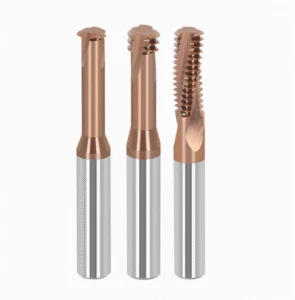
High-Precision Control for UNC/UNF Thread Milling
When exporting precision parts to North American aerospace, energy, or medical clients, Unified National threads dominate the print. We frequently see shops treat Class 2B or 3B fits like standard metric 60-degree threads. The result is predictable: the no-go gage stops, but the go-gage binds halfway down. Cutting internal UN threads in HRC65 steel leaves zero room for tool deflection or root-profile error.
Imperial coarse and fine threads differ widely in pitch height and teeth per inch (TPI). This requires high interpolation resolution from your CNC control during three-axis motion. In our field runs, holding 3B tolerances with a UNC UNF carbide thread mill depends on spatial toolpath planning. Balancing root clearance with flank cutting pressure determines whether parts pass CMM inspection on the first article.
Machining Imperial Threads: Pitch Diameter and Crest/Root Tolerances with UNC UNF Carbide Thread Mills
Fine threads (UNF) have shallower profiles, concentrating shear stress along a smaller engagement zone. Coarse threads (UNC) require deeper single-point cuts, generating heavier tool pushback. To hold strict Class 3B tolerances, never substitute a metric 60-degree cutter. A dedicated UNC UNF carbide thread mill features precision-ground flat crests and rounded roots, preventing go-gage binding caused by incorrect thread root flats.
Flank springback is another critical factor in hardened materials. Instead of programming dead-on nominal pitch diameter, we offset tool radius compensation toward the high side by 0.01 mm. Cutting resistance pushes the tool back just enough to land the thread right in the sweet spot. This stops go-gages from sticking while keeping your pitch diameter safely away from no-go gage limits.
Bottoming Threads in Blind Holes: Clearance Design and Chipping Prevention
Drawings for manifold blocks and mold plates often demand full thread depth right down to the drill point. Operators often plunge the cutter straight down, slamming the bottom tooth into chips or the drill cone. For tight blind holes, tool designs must feature an undercut bottom face and minimal end chamfer. This tight packaging keeps the unthreaded gap at the bottom below 0.5 pitches.
Your toolpath must also avoid plunging directly into the hole bottom. Always leave a clearance gap of 0.3 mm to 0.5 mm between the tool tip and the pre-drilled bottom. Never let the tool face drag across chips or the drilled cone. If the drawing demands full flat threads, run a flat-bottom carbide drill first to clear the seat before sending in the thread mill.
Layered Helical Interpolation: Smooth Engagement and Zero-Gouge Retraction
Hardened steel chips instantly if a tool plunges straight into the sidewall. Always program a smooth 90-degree or 180-degree tangential arc entry via helical interpolation. This ramps chip thickness gradually from zero to target chip load. For steels above HRC60, split the radial cut into three or four passes: roughing, semi-finishing, and a final spring pass to divide cutting forces evenly.
Retract toolpaths require equal care. Novice programmers often pull the tool straight back to center along the X/Y axis right after the cut. Any unreleased tool deflection drags the cutter across the finished flank, gouging the pitch diameter. Always roll off the wall with a tangential exit arc, return to center, and then rapid out along the Z-axis.
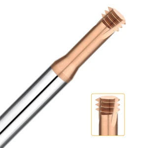
Cutting Parameter Libraries and Shop-Floor Optimization: Practical Application of Speeds, Feeds, and Toolpaths for Carbide Thread Mills
Many operators instinctively run catalog speeds on hardened materials, only to watch tool tips anneal or hear spindles screech. In our field optimization of carbide thread mills, the most frequent mistake is ignoring internal circular feed conversion. CNC controls calculate feed at tool center, not tool edge. Neglecting toolpath compensation on small bores spikes actual cutting load up to three times over programmed values.
Hardened stock requires dynamic, gradual parameter tuning. Spindle balance, way rigidity, and part clamping pressure all heavily impact tool survival. We recommend conservative surface speeds paired with deliberate chip load. Never let a carbide edge rub or burnish an HRC65 surface. Friction without cutting causes rapid edge fatigue and micro-spalling within minutes.
Radial Multi-Pass Strategy: Feed per Tooth (fz) and Multi-Pass Settings for High-Hardness Materials
Forming full thread depth in a single pass past HRC60 guarantees tool failure. For hardened tool steels, we run a multi-pass strategy using 3 to 4 radial stepovers. Remove 50% stock on pass one, 30% on pass two, 15% on pass three, and 5% (roughly 0.015 to 0.02 mm) on the final spring pass. This stepped-load pattern cuts tool deflection down to bare minimums.
Feed per tooth (fz) defines success on high-hardness parts. We always warn machinists: never drop fz too low. If feed drops under 0.005 mm per tooth on hardened layers, the edge rubs instead of cutting. Friction spikes immediately, burning off the coating. Maintaining a solid, crisp chip load ensures clean shear action and carries heat away inside the chip.
| Machining Pass | Radial Stock Removed (ae) | Cutting Speed Vc (m/min) | Feed per Tooth fz (mm/z) | Process Objective |
| Pass 1: Roughing | 50% full thread depth | 35 – 45 | 0.015 – 0.025 |
Smooth arc roll-in, removes heavy core stock
|
| Pass 2: Semi-Finishing | 30% full thread depth | 40 – 50 | 0.015 – 0.020 |
Evens out wall stock, stabilizes cutting load
|
| Pass 3: Profiling | 15% full thread depth | 40 – 50 | 0.010 – 0.015 |
Sets true pitch diameter, eliminates wall taper
|
| Pass 4: Spring Pass | 5% (approx. 0.02 mm) | 45 – 55 | 0.005 – 0.008 |
Cleans microscopic burrs, ensures gage fit
|
Practical Evaluation of Tool Clamping Systems: The Impact of Shrink-Fit and Hydraulic Chucks on Thread Surface Roughness
If you use standard ER collet chucks for small thread mills in hardened steel, swap them out immediately. Standard collet chucks routinely show dynamic runout over 0.01 mm at high RPM. In HRC65 stock, runout forces a single tooth to take the entire cut load alone. We routinely see tools shatter in seconds simply because one tooth was overloaded by runout.
Shrink-fit and high-precision hydraulic chucks are mandatory baselines. Shrink-fit holders deliver extreme rigidity and slim profiles for tight cavity reach. Hydraulic holders dampen high-frequency harmonics, creating mirror-like thread flanks. Dial in your tool assembly and keep runout at the tip under 0.003 mm. That single step prevents chatter marks and uneven thread crests.
Thread Gauge Failing Inspection? Troubleshooting Profile Deformations and Taper Defects
When the no-go gage stops but the go-gage binds after two turns, do not alter your programmed pitch. The thread pitch is rarely wrong; tool shank deflection is causing hole taper at the bottom. The fix is straightforward: program a reverse taper compensation into your subprogram, or run an zero-depth spring pass along the same path to sweep out deflected stock.
If the go-gage enters but the no-go gage turns past three quarters, your finish pass pushed off or torn the crest. Dull edges build high pressure that spreads metal into raised burrs, distorting pitch diameter. If no-go inspection fails, confirm your air blast clears packed chips from the bore, then check machine axis backlash during circular interpolation.
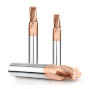
B2B Procurement and Technical Assessment: A Checklist for Obtaining Accurate Carbide Thread Mill Quotations
In our customer technical support work, the most challenging inquiry is a vague RFQ stating: “Quote M6 thread mill for hardened steel.” Without material hardness numbers, hole depth-to-diameter ratios, and machine spindle specifications, any quick quote just leads to broken tools on your floor. Securing an accurate carbide thread mill quotation requires upfront technical alignment between your shop engineers and our tooling team.
A structured technical review stops trial-and-error costs before cutting metal. If you are setting up jobs in quenched mold steels, aerospace superalloys, or hardened stainless, review your setup systematically. Check workpiece heat-treat certification, spindle runout limits, and custom neck clearance needs. Thorough parameter verification upfront ensures your custom cutter performs smoothly right on the first-article test cut.
Avoiding Selection Errors: Key Tolerances and Hardness Parameters to Verify Before Requesting a Carbide Thread Mill Quotation
Tooling errors usually start with generic hardness callouts. A workpiece at HRC58 cuts completely differently than one at HRC65 in lateral pushback and carbide abrasion. Similarly, a standard Metric 6H clearance band differs vastly from an aerospace Class 3B fit. Before requesting a carbide thread mill quotation, verify your exact print callouts: is it standard clearance or a tight pitch-diameter fit under cyclic fatigue?
If you are cutting S136, D2, or cold-work steels past HRC60, specify your required thread depth and pilot hole floor limit. This tells us whether to design a thick-web core for beam rigidity, or adjust flank tooth geometry to counter material springback. Providing exact hardness windows, depth-to-diameter values, and gage inspection standards eliminates production scrap before batch machining starts.
Customizing Carbide Thread Mills for Western Markets: Key Considerations for Non-Standard Pitches and Extended Neck Clearance
In automotive stamping dies and manifold blocks, machinists frequently hit stepped cavities, angled entries, or tight relief grooves. Standard catalog tool necks often rub cavity shoulders. When stock tools fall short, engineering custom carbide thread mills requires balancing neck reach against dynamic tool rigidity. Lengthening tool neck reach by even 5 mm exponentially increases bending moments at the tip, making transition blend angles vital.
If you face deep holes over 3:1 L/D or complex multi-start threads, share your 3D CAD section or hole detail prints with us. We can map out tool clearance, add concave end reliefs to bottom out blind threads, or adjust flute helix angles to suppress deep-hole chatter. Real engineering support is not just pricing part numbers—it is two machining specialists tailoring a rigid cutter setup to your exact machine spindle and hardened workpiece.