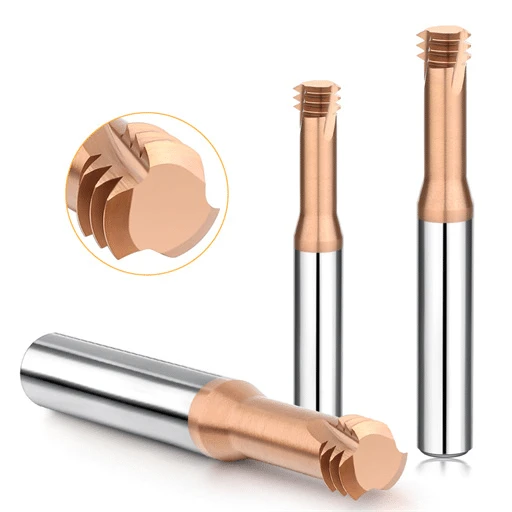
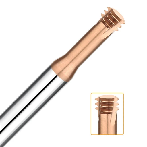
A mold-making client once came to us with a batch of die components heat-treated to roughly HRC62. The first few holes threaded cleanly, but dimensional drift quickly followed. Burrs formed along the hole entries, and inspection revealed micro-chipping on the tool teeth. The shop had not altered their program or setup, but their cutting conditions were pushing the edge limits for thread milling hardened steel.
We see this scenario routinely across precision tooling shops. Working in the HRC60–HRC65 window fundamentally alters cutting edge mechanics, tool wear patterns, vibration harmonics, and chip clearance. Standard parameters simply do not transfer to these alloys. Without dialling in radial engagement, feed rates, surface speed, and entry toolpaths, edge breakdown or catastrophic tool failure is inevitable in HRC60–HRC65 thread milling.
Machining high-hardness steel is never as simple as dropping the spindle speed. We assess the entire machining envelope: workpiece hardness, pitch, thread depth, machine rigidity, and holder runout. When running solid carbide thread mills on HRC62–HRC65 stock, harder carbide grades are not an automatic fix. Edge stability and process balance matter far more than substrate hardness alone.
The primary hurdle in thread milling hardened steel is not getting through the cut; it is holding thread tolerance and edge life across a full production run. Machining high-wear tool steels like D2 or SKD11 creates extreme radial cutting loads. Deep-hole threads, small pitch diameters, and extended overhangs multiply tool deflection, accelerating abrasive flank wear and chipping.
Rather than rehashing basic machining concepts, this guide shares hands-on shop floor strategies refined across dozens of hardened tooling projects. We examine tool geometry, cutting feeds and speeds, arc-in toolpaths, and chatter control for HRC60–HRC65 materials. Using practical D2 tool steel examples, we pinpoint why a setup yields a flawless first thread but fails fifty parts later.
If your thread mills cut the metal but leave you battling erratic tool life, pitch error, or chipping, changing cutters rarely solves the root cause. Reliable HRC60–HRC65 thread milling requires auditing and optimizing the complete machining system from the spindle to the cutting edge.
Thread Milling Hardened Steel: Common Challenges in the HRC 60–65 Range
In high-hardness mold manufacturing, clients often struggle when threading steels treated to HRC 62–64, especially across continuous blind holes. A job might produce perfect threads initially, but microscopic cutting edge chipping appears after a dozen holes, causing immediate pitch diameter drift. Diagnosing this requires looking past the cutter itself to audit tool overhang, holder runout, and machine rigidity.
When thread milling hardened steel, cutting load consistency dictates your outcome. Materials at this hardness level offer immense cutting resistance that concentrates heavy stress on the tool edge during helical interpolation. Without rock-solid rigidity and clean chip evacuation, mechanical deflection escalates into chatter and premature edge failure—a dynamic we monitor constantly during thread milling HRC 65 steel.
Why Edge Chipping and Chatter Are More Common When Thread Milling HRC 60–65 Steel
Micro-chipping along the cutting edge is far more common than catastrophic breakage in the HRC 60–65 hardness range. Small diameters and deep holes force longer tool overhangs, reducing structural rigidity and amplifying cutting harmonic vibrations at the tool tip. These micro-vibrations quickly degrade the cutting edge, leaving chatter marks on the thread flanks and ruining surface finish.
One client blamed cutter quality after new tools repeatedly chipped after just a few parts. Our tooling audit revealed the true culprit: excessive overhang paired with an aggressive radial depth of cut. If you face chatter while thread milling HRC 65 steel, check holder runout, verify clamping rigidity, and reduce radial engagement before swapping out tooling grades.
Assessing Machining Difficulty Based on Thread Dimensions, Hardness, and Hole Depth
Evaluating a hardened steel application requires balancing thread pitch, nominal diameter, workpiece hardness, and hole depth simultaneously. Machining an M12 thread in shallow tooling behaves entirely differently than cutting an M4 thread at three times diameter depth. Small diameters severely restrict tool core thickness, while jumping from HRC 60 to HRC 65 multiplies edge stress exponentially.
Blind holes introduce additional danger because limited bottom clearance complicates helical ramping and chip exit paths. When managing thread milling hardened steel projects, we never assess difficulty by material hardness alone; we evaluate the entire tool-workpiece interface. Identifying your weakest setup link first makes it simple to optimize overhang, adjust cutting loads, or select rigid tool geometries.
Machining Conditions Most Likely to Cause Premature Failure of Hardened Steel Thread Mills
Premature failure typically stems from stacked process errors rather than a single incorrect feed rate. High cutting speeds combined with excessive runout, long gage lengths, and aggressive radial cuts create peak thermal and mechanical loads that fracture carbide teeth. Trapped chips that recut inside the hole accelerate abrasive flank wear and trigger instant edge breakdown.
Sudden load spikes during straight linear tool entries are equally destructive to brittle carbide edges. Successful thread milling hardened steel demands smooth tangential arc-in and arc-out toolpaths to stabilize cutting pressure across every pass. Instead of dropping speeds blindly, isolate the specific shock zones in your toolpath and refine radial step-overs to secure consistent tool life.
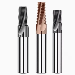
How to Choose a Thread Mill for Hardened Steel
Selecting cutters for high-hardness molds requires looking beyond raw material specs. We evaluate hardness, nominal diameter, thread pitch, hole depth, and spindle rigidity together. An M12 shallow hole behaves completely differently from an M4 deep blind hole at HRC 62. For deep features, we verify effective overhang and runout first when selecting a thread mill for hardened steel.
Cutter diameter relative to hole diameter is just as critical. An oversized cutter restricts the helical path and risks thread profile distortion through overcutting. A tool that is too small reduces cutting loads but flexes under long reach, slowing cycle times. The best choice balances structural rigidity, radial cutting forces, and chip clearance rather than simply picking the largest available tool.
How Solid Carbide Thread Mills Handle HRC60–HRC65 Steel
We prioritize solid carbide tooling for HRC 60–65 applications involving tight tolerances, small diameters, or deep reaches. The ultra-fine micro-grain substrate provides the high elastic modulus needed to resist structural deflection. When machining hardened materials, excessive tool flex ruins thread pitch accuracy, degrades surface finish, and triggers premature edge chipping.
A mold client cutting HRC 63 steel faced continuous micro-chipping using standard-geometry tools. Instead of dropping spindle speed, we switched to a heavy-core carbide cutter with reinforced edge hone and optimized their radial toolpath. Premium solid carbide thread mills succeed in HRC 60–65 steel by preventing edge micro-fractures under continuous cut loads, not just surviving the initial pass.
Selecting a Thread Mill Based on Thread Diameter, Pitch, and Machining Depth
Every tooling evaluation starts with thread geometry: major diameter, pitch, usable thread depth, and hole type. When choosing a thread mill for hardened steel in deep holes, tool deflection matters far more than simple flute length. Single-point or short-profile thread mills are often best for deep internal threads because they minimize radial contact and eliminate chatter.
Thread pitch dictates edge stress and contact area. Coarse-pitch threads face higher tooth engagement and require generous chip clearance, while fine-pitch threads demand extra edge strength to handle thin, hard chips. Never hand a tooling vendor just the basic thread size; provide thread pitch, full hole depth, and spindle interface data to guarantee the right tool geometry.
How Flute Count, Core Diameter, and Cutting Edge Geometry Affect Thread Milling in Hardened Steel
Flute count and web thickness dictate the trade-off between cutter rigidity and chip space. More flutes yield higher feed capability and structural support, but narrow the flute valleys where chips escape. When thread milling hardened steel, choosing between a 3-flute or 4-flute design depends entirely on hole diameter, thread pitch, and chip evacuation limits.
Core diameter and cutting edge prep govern tool stiffness under lateral load. A slender neck deflects and chatters under minimal overhang, but an oversized core causes chip packing in blind holes. Reliable performance requires balanced engineering—pairing a rigid core, stable helix angle, and micro-honed edge prep to withstand continuous radial cutting pressure without chipping.
Hardened Steel Thread Milling Parameters: Adjusting Parameters for HRC 60–65 Materials
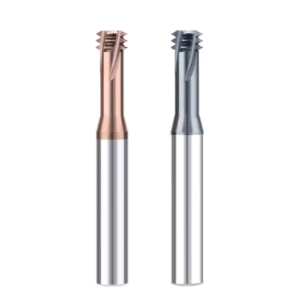
Dialing in high-hardness jobs requires moving past static catalog speeds and feeds. In our shop, we calculate an initial baseline using cutter diameter, flute count, reach, and pitch before establishing a safe machining window. On a run of HRC 62 mold cores, a client saw rapid pitch drift because their setup lacked safety margin; isolating surface speed, chip load, and step-over restored process stability.
Real-world cutting verifies what software predicts. We actively track spindle load spikes, chip formation, flank wear, and pitch accuracy before refining our baseline hardened steel thread milling parameters. Approaching HRC 65 leaves zero margin for aggressive trial-and-error; achieving vibration-free, predictable cuts across dozens of holes always takes priority over shaving two seconds off cycle time.
Setting Thread Milling Speed and Spindle RPM for Hardened Steel
Spindle RPM must be calculated from target surface footage (SFM) and tool cutting diameter, never guessed. A 4mm cutter requires drastically different RPM than an M12 thread mill to achieve identical cutting action in 60+ HRC steel. We establish baseline SFM from manufacturer data, calculate operating RPM, and verify cutting temperatures and spindle harmonics during continuous test cuts.
One client blamed excessive RPM for tool failure in HRC 64 mold cavities and dropped their speed drastically, but teeth kept chipping. Our inspection traced the failure to excessive tool stick-out and heavy radial engagement, which caused deflection. When setting your thread milling speed, never lower RPM in isolation without balancing radial depth and overall cutting pressure.
How Feed Rate and Chip Load Affect Thread Mill Cutting Loads
Feed rates must be evaluated as chip load per tooth () along the internal helical arc rather than simple table feed (IPM). With ultra-hard steels, an excessive chip load causes micro-chipping on the tooth tips, while an insufficient chip load causes rubbing, rapid work hardening, and friction burn. We monitor spindle draw and acoustic signatures to confirm the tool is cleanly shearing material.
Lowering the feed rate too far is just as destructive as overfeeding. We frequently see operators drop feed rates to protect a delicate tool, only to generate extreme frictional heat that burns off tool coatings. When tuning hardened steel thread milling parameters, choose a chip load that forms distinct, curled micro-chips while avoiding chatter-inducing tool deflection.
Managing Machining Loads for HRC65 Materials via Radial Engagement and Axial Depth
Controlling radial engagement is vital because the cutter experiences continuous circular deflection during internal helical interpolation. High radial depth of cut () spikes cutting resistance, instantly chipping fragile carbide tips. When thread milling HRC65 components with long overhangs or small diameters, splitting the thread depth into multiple radial passes stabilizes cutting pressure and protects the tool.
Axial depth of cut () must match the structural rigidity of the cutter and hole depth. Pushing full axial engagement in deep blind holes introduces severe tool bending forces. For deep-reach threads, we favor multi-pass strategies or staggered-tooth thread mills over heavy single-pass cuts to eliminate chatter, maintain thread perpendicularity, and safeguard tool life.
Why the Same Thread Mill Cannot Use Identical Parameters for HRC60 and HRC65
Assuming identical cutting parameters will work across HRC 60 and HRC 65 simply because the alloy family is unchanged is a costly mistake. Cutting resistance scales non-linearly above 60 HRC, multiplying shear stress on cutting edges and accelerating abrasive flank wear. Treating HRC 60 and HRC 65 as separate machining environments prevents sudden tool failure during batch production.
In our production testing across hardened tool steels, parameters running smoothly at HRC 60 caused instant edge degradation at HRC 64. Instead of slashing speeds blindly, we take an incremental approach: lock in structural rigidity, dial in chip load, and refine radial passes. Optimizing hardened steel thread milling parameters demands methodical step-by-step verification to achieve maximum tool life and accurate threads.
Hardened Steel Thread Milling Toolpaths: How We Design Toolpaths for HRC 65 Materials
Dialing in spindle speed and feed rate will not fix a flawed entry trajectory. In our shop, edge chipping at hole entry or mid-cut chatter usually traces back to aggressive linear engagement, abrupt motion transitions, or lateral drag during retract. At extreme hardness levels, even minor programming shortcuts generate destructive shock loads that brittle carbide edges cannot survive.
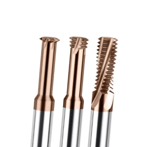
A dependable hardened steel thread milling toolpath requires full control over the cutting forces at every phase: entry, helical interpolation, and exit. We program dedicated lead-in and lead-out vectors to build cutting resistance gradually rather than running simple point-to-point tool movements. With HRC 65 materials, investing CAM time into smooth toolpaths directly protects your tool edge and extends production tool life.
Why Controlling Radial Engagement is Critical for HRC 65 Thread Milling
Taking full thread depth in a single radial pass is the fastest way to ruin a cutter in 65 HRC steel. The instantaneous load spike upon entering full stock engagement triggers immediate edge micro-fracturing and severe chatter. Splitting the total allowance into multiple radial roughing passes and a light finishing pass keeps cutting pressures manageable and protects tool life.
On an HRC 63 mold core, an operator struggled with aggressive vibrations midway through the cut using a single-pass strategy. We redistributed the radial allowance across three passes, sizing step-overs to the tool’s core diameter and setup rigidity to eliminate the vibration. When troubleshooting chatter in thread milling HRC65 materials, reduce your radial depth of cut before touching spindle RPM.
Choosing Between Climb Milling and Entry Methods for Thread Milling
Climb milling remains the industry standard for high-hardness materials because it controls the force vector against the cutting edge. Starting with a thick chip that tapers to zero thickness prevents rubbing, reduces tool wear, and yields excellent thread flank finishes. We verify internal helical direction carefully in CAM to ensure the cutter stays in true climb mode throughout the cycle.
Tool lead-in strategy is equally critical. Plunging straight into cut engagement delivers a severe mechanical impact that chips cutting edges. We program 90° or 180° tangential arc entries for an HRC65 thread milling toolpath, allowing cutting forces to build smoothly from zero to full depth. A controlled arc entry often extends tool life more effectively than dropping spindle speed by hundreds of RPM.
How Helical Toolpaths Affect Cutting Load and Thread Surface Quality
Thread milling demands precise, simultaneous 3-axis motion where continuous circular interpolation matches the axial pitch lead per revolution. Any stutter or uneven acceleration between the XY circular arc and Z-axis motion causes immediate cutting load spikes. Seamless block transitions and proper look-ahead settings in the CNC control are vital for maintaining constant cutting resistance.
We resolved a persistent chatter issue on HRC 62 tooling components by smoothing the helical motion parameters in CAM. Even with correct cutting tools and clean pilot holes, irregular axis acceleration had introduced periodic micro-vibrations across the thread flanks. A well-tuned hardened steel thread milling toolpath ensures steady mechanical loading, producing flawless surface finishes and consistent thread pitch diameter.
Handling Tool Retraction and Chip Evacuation in Blind Hole Thread Milling
Blind hole threading leaves zero room for chip evacuation errors. Without an open bottom, hard micro-chips settle in the hole bottom; recutting these chips creates extreme friction that instantly breaks fragile carbide teeth. We program precise bottom clearances, employ high-pressure through-spindle air blasts, and eliminate any tool dwell at the bottom of the cut.
On a production run, a client experienced repeated tool breakage caused entirely by chips packing into the pilot hole relief. We adjusted the Z-axis endpoint, increased the bottom safety gap, and revised the retract arc to exit smoothly without dragging. Designing a reliable hardened steel thread milling toolpath for blind holes requires verifying bottom clearance, chip evacuation paths, and clean retract clearance above all else.
Hardened Steel Thread Milling Accuracy: How We Control Thread Precision at HRC 60–65
A precision-ground tool never guarantees an in-spec thread profile on its own. In our shop, an HRC 63 mold tooling batch produced an acceptable first thread, but Go/No-Go plug gauges began failing midway through the run. Rather than assuming the cutter was dull, a full teardown revealed subtle spindle runout and excessive tool stick-out that distorted the pitch diameter.
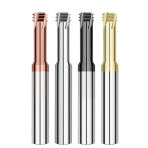
True hardened steel thread milling accuracy requires auditing the dynamic cutting chain rather than solely relying on post-machining measurements. Extreme material hardness magnifies microscopic flex in the spindle, holder, and pilot hole into severe pitch diameter errors. Isolating deflection sources, holder slippage, and load spikes protects thread quality far better than blind offset tweaks.
How Tool Runout Affects Hardened Steel Thread Milling Accuracy
Dynamic tool runout is the primary cause of thread gauge failure in high-hardness milling. A tool indicating true at static zero can run eccentric under rotational load, loading one flute heavily while others cut air. This uneven contact produces asymmetrical thread flanks, rapid single-edge chipping, and pitch failure, especially on small-diameter thread mills.
We measure total indicator reading (TIR) on the fully assembled toolholder directly at the cutter’s neck. If you notice asymmetric flank wear or chatter during production, verify holder-to-taper concentricity before altering your CNC program. For HRC 60–65 jobs, achieving superior hardened steel thread milling accuracy starts with locking assembly runout under 0.0002″ (0.005mm).
Controlling Thread Milling Tolerance via Toolpaths and Radial Allowance
Cutting directly to final pitch diameter in a single radial pass consistently causes gauge rejection in hardened steels. Heavy roughing forces induce tool deflection that leaves threads tapered or undersized. We divide the cutting envelope into multiple radial passes, reserving a dedicated spring pass with minimal stock to lock in thread dimensions.
On an HRC 62 mold component, a single-pass toolpath caused continuous gauge rejection as cutter pressure drifted. Allocating stock across two roughing passes and one light finish pass stabilized the cutting forces and held pitch tolerances. When controlling your final thread milling tolerance, decoupling roughing deflection from final sizing ensures consistent pitch diameters.
How Machine Rigidity, Tool Holders, and Workpiece Clamping Affect HRC65 Thread Milling Accuracy
Even the most advanced thread mill fails in a weak machine setup. At 65 HRC, long gauge lengths, worn collets, or inadequate fixturing turn cutting forces into structural vibration. Tool deflection pushes the cutter away from the programmed arc, producing tapered threads and ruined lead pitches that no software compensation can correct.
We solved an inconsistent sizing issue by swapping a standard collet chuck for a high-rigidity hydraulic holder and choking up on cutter stick-out. Stabilizing your HRC65 thread milling accuracy demands evaluating the entire spindle-holder-tool-workpiece assembly. Rigid clamping and minimal overhang prevent the minute component deflections that are often misdiagnosed as cutter wear.
Adjusting the Thread Milling Path for Oversized or Undersized Threads
Treating size deviations with simple offset tweaks usually masks deeper physical cutting problems. We first determine if the error is repeatable across every hole or drifting over time. A repeatable error points to CAM radius or nominal tool geometry offsets, while gradual dimensional drift signals flank wear, thermal growth, or excessive tool push-off.
When thread size runs undersized, inspect the teeth for micro-chipping or edge wear before bumping radial compensation. If threads run oversized, check assembly runout and machine taper condition before adjusting the toolpath radius. Systematic troubleshooting distinguishes programming errors from setup deflection, keeping your overall thread milling accuracy stable across production batches.
Hardened Steel Thread Mill Tool Life: How We Extend Tool Life for HRC65 Materials
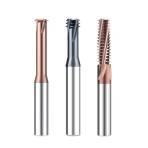
Evaluating cutter longevity goes far beyond tallying total hole counts. On an HRC 62–64 mold tooling run, a customer targeted 30 holes per cutter, but pitch diameters drifted after hole 14. While the carbide teeth had not fractured, edge degradation caused immediate gauge failures. Practical hardened steel thread mill tool life means maintaining pitch accuracy, finish quality, and cutting edge stability across the entire batch.
We track tool wear through four distinct stages: initial break-in, steady abrasive wear, rapid acceleration, and failure. Monitoring spindle load draw, acoustic pitch, and edge micro-wear under magnification pinpoints the ideal tool change point. In 60+ HRC steels, premature failures spike once initial wear begins; pulling the tool at the right window prevents scrapped parts and broken cutters.
Factors That Most Easily Shorten Hardened Steel Thread Mill Tool Life
Cutter failure rarely stems from a single incorrect setting, but rather from compounding setup errors. Excessive tool stick-out, heavy radial passes, loose toolholder collets, and poor machine rigidity multiply lateral deflection in high-hardness steel. On an HRC 63 job where life was cut in half, reducing overhang and dialing back radial step-over stabilized the process immediately without changing cutter grades.
Chip packing is another primary driver of premature failure in blind holes. When micro-chips cannot escape the cavity, the cutter recuts them against the hardened wall, instantly breaking brittle carbide tips. High-pressure through-spindle air blast or directed coolant clears debris effectively. Before replacing worn tools with expensive specialty grades, eliminate chip packing, runout, and excessive radial loads.
Assessing Thread Mill Wear: Flank Wear vs. Edge Chipping
Distinguishing predictable flank wear from brittle micro-chipping is critical for root-cause diagnosis. Uniform flank wear develops gradually along active relief faces, signaling normal abrasive life that you can track with dimensional offsets. In contrast, microscopic edge nicks indicate shock loading or chatter, showing that your thread mill tool life is ending prematurely from mechanical failure.
Edge chipping requires immediate intervention. On an HRC 65 setup, a single chipped tooth rapidly escalated into complete tool failure, leaving torn threads in its wake. If an inspection reveals localized tooth fractures rather than smooth, even abrasive wear, stop the machine immediately. Investigate spindle runout, entry toolpaths, and radial engagement rather than pushing the tool to catastrophic failure.
Why Reducing Radial Engagement Can Be More Effective Than Simply Lowering RPM
Dropping spindle speed is often the wrong first response to chipping in HRC 65 materials. A client milling HRC 64 mold cavities slashed spindle speed to resolve edge micro-fracturing, yet the teeth continued to chip. The true issue was an aggressive radial depth of cut that overloaded the cutter upon entry; reducing radial step-over cured the failure immediately.
Carbide tool life balances thermal limits against mechanical shear stress. Lowering RPM relieves thermal load, but it does nothing to mitigate excessive lateral deflection and bending forces. When thread milling HRC65 materials, dividing the stock into multiple shallow radial passes reduces tooth pressure, eliminates deflection, and protects cutting edges far better than simply slowing down the spindle.
Improving Thread Mill Tool Life through Machining Parameters, Toolpaths, and Chip Evacuation
Maximizing tool performance requires synchronizing cutting speeds, CAM toolpaths, and chip clearing. We calculate conservative baseline parameters matching workpiece hardness, cutter flute count, and thread pitch. In CAM, programming tangential arc lead-ins and distributing stock across multiple radial passes prevents the severe impact spikes that fracture carbide edges on entry.
Chip control is equally vital in deep blind holes. High-pressure air blasts clear hardened debris from the hole bottom, preventing recutting and localized edge burn. Ultimately, maximizing hardened steel thread mill tool life is not about squeezing out one lucky test hole; it is about establishing a repeatable, stable machining window that guarantees quality on every single part.
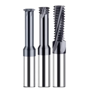
Thread Milling D2 Steel – Our Practical Experience with HRC 60–65 D2 Steel
Machining high-wear tool steels like D2, 1.2379, or SKD11 requires evaluating the heat-treated microstructure rather than the raw alloy grade. D2 contains massive, hard chromium carbides dispersed in a high-carbon matrix, making it intensely abrasive after hardening to HRC 60–63. While cutting a single thread is straightforward, maintaining pitch diameter and edge integrity across a production run demands tight process control.
When thread milling D2 steel, we verify workpiece hardness, pilot hole runout, and usable thread depth before selecting tooling. Pushing standard cutting parameters into 60+ HRC D2 causes immediate edge failure. A reliable setup requires rigid toolholders, minimal overhang, shallow radial cuts, and clean chip evacuation; dial in these structural fundamentals before attempting to optimize spindle speeds and feed rates.
Adjusting Cutting Parameters Based on Hardness When Thread Milling D2 Steel
Heat treatment dramatically alters how D2 steel reacts under cutting loads. Parameters that run smoothly in pre-hardened stock cause instant tooth chipping and pitch diameter drift at HRC 60–63. The dense carbide matrix rapidly abrades cutting edges, so any jump in Rockwell hardness requires recalculating surface speed, radial engagement, and chip load per tooth ($f_z$).
Avoid adjusting every variable simultaneously when stabilizing your cuts. We lower the radial depth of cut ($a_e$) first if spindle load spikes, and adjust surface footage only when observing thermal flank wear. Optimizing your process for thread milling D2 steel relies on defining a tight, hardness-specific operating window through test cuts rather than recycling generic catalog feeds across HRC 60 and HRC 65.
Troubleshooting Chipping, Chatter, and Thread Accuracy Issues in D2 Steel Thread Milling
Locating exactly where teeth chip reveals the physical root cause of tool failure. Damage occurring right at lead-in points to aggressive radial entry paths; chipping deep inside a blind hole signals chip packing; and uneven wear on one side indicates holder runout. Pinpointing the failure zone isolates tooling defects from system deflection, preventing wasteful, repetitive tool swaps.
Chatter and thread gauge failure require a structured diagnostic process. On an HRC 62 stamping die, pitch diameters drifted oversize because tool stick-out and collet runout were excessive for the material’s cutting resistance. When troubleshooting thread milling D2 steel, follow a strict sequence: audit assembly runout, reduce overhang, verify clamping rigidity, and drop radial step-over before altering CAM programs.
Key Considerations When Machining Hardened D2 Steel with Solid Carbide Thread Mills
Threading hardened D2 demands high-rigidity solid carbide tools engineered with thick core diameters, micro-honed edges, and heat-resistant coatings like AlTiN or AlCrN. The intense radial resistance generated by hard chromium carbides deflects weak tools, causing rapid flank wear and taper. A tough, sub-micron substrate resists premature fracturing far better than brittle, ultra-hard grades.
Thread reach also governs cutter selection. While standard flute lengths work for shallow holes, deep holes require dedicated short-flute or single-point thread mills to prevent deflection. An extended-reach tool may have sufficient flute length on paper, but lacking neck rigidity will induce severe chatter. Always verify that your cutter maintains sufficient structural stiffness at full gauge depth.
Improving Thread Mill Tool Life for D2 Steel Through Machining Conditions
Predictable tool life in D2 steel means gradual, uniform flank wear rather than sudden edge fractures. The abrasive chromium carbides in the alloy cause steady wear, but micro-chipping occurs when mechanical cutting pressures spike. Dropping spindle speed will not solve edge fractures if excessive radial engagement is causing tool deflection and shock loading.
Extending thread mill tool life in D2 requires balancing surface footage, radial step-overs, tangential arc lead-ins, and high-pressure air blasts. When tooth tips fracture, reduce mechanical cutting loads immediately; when flank wear accelerates, verify coating compatibility and surface speed. Consistent batch production depends on holding pitch tolerance across every hole, not gambling on maximum hole counts from a single cutter.
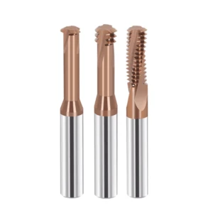
Troubleshooting Thread Milling in HRC60–HRC65 Steel: Solving Common Machining Issues
Troubleshooting high-hardness machining issues requires evaluating the dynamic cutting environment rather than blaming the cutter. A tool that fails on hole one points to gross mechanical error, whereas failure on hole twenty indicates thermal fatigue or edge wear. When troubleshooting thread milling in HRC60–HRC65 steel, tracking the exact failure point separates tooling defects from structural instability.
Before swapping cutters, document every symptom: tooth fracture location, pitch diameter variance, surface chatter patterns, and part cycle counts. In our production facility, these physical clues pinpoint the root cause immediately. Methodical tracking reveals whether you are fighting improper cutting parameters, inadequate tool core stiffness, or severe workholding deflection.
What to Check First When Thread Mills Chip in HRC65 Steel
When cutting teeth fracture, audit tool stick-out and holder runout before altering spindle speed. Inspect precisely where the tooth chipped along the profile. Fractures at the leading edge indicate shock loading during linear entry, while fractures near the tool tip point to chip packing at the bottom of the hole.
If you face recurring tooth chipping during thread milling HRC65 steel, compare the last good hole against the first failed cut. Check for spindle load spikes, chipped pilot drills, or recut chips. If the setup is unchanged, verify core hardness across workpiece batches to avoid replacing good carbide cutters needlessly.
Troubleshooting Tool Runout, Toolpaths, and Parameters for Unstable Thread Dimensions
Isolating dimensional drift requires determining whether pitch error starts on the first hole or develops gradually. Immediate failure points to excessive holder runout, an undersized pilot hole, or tool push-off. Gradual pitch expansion or shrinkage across a batch signals abrasive flank wear and mounting cutting resistance.
Always measure dynamic runout at the tool neck and verify finish radial stock before tweaking CAM offsets. Offsetting a dull, chipped cutter in software only accelerates tool destruction on subsequent parts. Successful thread milling hardened steel requires separating CNC programming offsets from progressive mechanical edge wear.
Adjusting Thread Milling Conditions to Address Chatter and Vibration Marks
Chatter marks on thread flanks rarely stem from excessive surface speed alone. Small-diameter cutters with long overhangs lack structural stiffness, making them deflect under heavy radial cuts. When cutting forces spike abruptly during entry, harmonic vibration travels through the cutter, ruining thread flank surface finish.
When eliminating chatter, reduce tool overhang and divide the stock into lighter radial passes before touching RPM. Verify that your toolpath uses a smooth tangential arc entry rather than a straight plunge. Lowering spindle speed on a deflecting tool only shifts the chatter frequency without curing the underlying structural flex.
Diagnosing the Cause of a Sudden Drop in Thread Mill Tool Life (Tool, Machine, or Workpiece)
When cutter longevity plummets unexpectedly, systematically isolate the cutter, the machine, and the workpiece. Inspect the tool for coating delamination, chipped teeth, and flank wear under magnification. Next, indicate the spindle taper and toolholder collet for runout, and confirm that clamping fixtures have not loosened.
Finally, verify actual workpiece hardness and pilot hole depth across raw material lots. We have resolved drastic drops in tool life by discovering that a new steel batch was heat-treated two Rockwell points higher than specified. Isolating each variable methodically locks in reliable hardened steel thread mill tool life across continuous production runs.