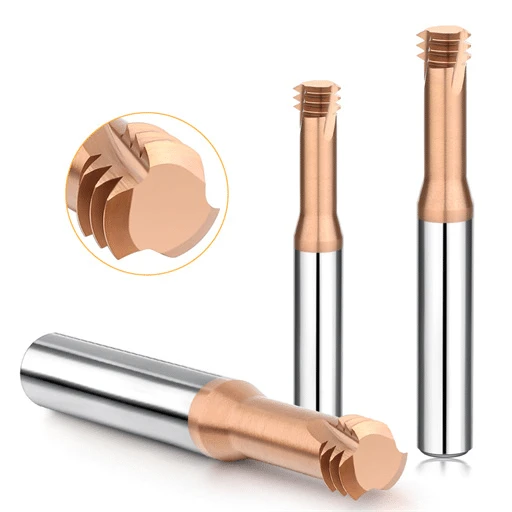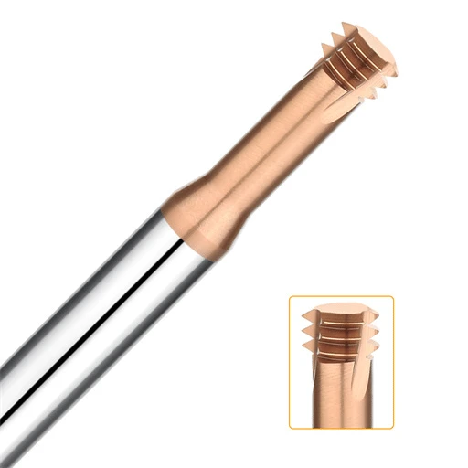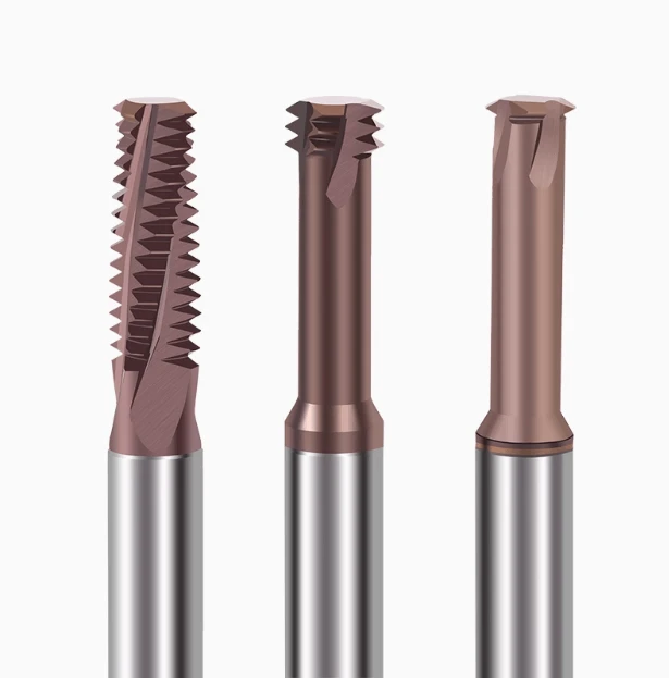
Last year, our shop tackled a tough mold steel project requiring tight-tolerance internal threads on material exceeding HRC60. The customer initially relied on single-point threading. While the first few parts passed inspection, tool wear quickly caused pitch diameter fluctuations and profile degradation during high-volume runs. Confined deep-hole features made chip evacuation difficult, and tweaking standard cutting feeds failed to stop scrap rates from climbing.
We see this standoff frequently on the shop floor: as material hardness climbs past HRC60 and tolerances tighten, choosing between thread milling vs single-point threading makes or breaks profitability. While both methods generate standard threads, they handle cutting forces and tool deflection completely differently. In high-hardness alloys (HRC62–HRC65), minor deflection directly ruins thread pitch accuracy, surface finish, and tool life.
For these hardened alloys, thread milling provides unmatched process control through helical interpolation, radial roll-in entry, and multi-pass profiling. Instead of taking heavy, continuous cuts, we divide radial chip loads across dedicated toolpaths. When running premium sub-micrograin carbide thread mills, we dial in surface footage and feed per tooth to the exact pitch and hole depth, protecting tool life while eliminating tapered threads.
Conversely, single-point threading on a rigid CNC lathe remains the fastest, most economical option for external threads and standard diameters. Rather than declaring one method universally superior, an experienced machinist weighs machine rigidity, batch volume, thread depth, and scrapped-part risk. The real decision hinges on total cost per hole: balancing tool investment against cycle time, setup versatility, and stable dimensional repeatability.
Thread Milling vs Single-Point Threading: Key Differences Observed in Practical Machining
When troubleshooting threads for clients, switching methods often creates unexpected pitch diameter shifts, profile errors, and accelerated wear. We look past the insert grade to analyze machine rigidity, tool overhang, and cutting force vectors. The contest of thread milling vs single-point threading comes down to how each process transfers load into the workpiece.
In production, thread milling relies entirely on multi-axis CNC interpolation and radial infeed strategy. Conversely, single-point turning depends on rigid workholding and stable insert tip engagement. When holding tight pitch tolerances in deep holes, evaluating chip clearance, spindle runout, and harmonic chatter matters far more than just switching tool brands.
Differences in Cutting Forces: Thread Milling vs Single-Point Threading
During a recent hardened mold project, single-point threading caused rapid dimensional drift as the tool nose degraded. Because cutting pressure concentrates on one delicate point, cutting forces spike with every successive pass. If you notice burrs or chatter, inspect each pass instead of blindly adjusting surface footage.
By comparison, thread milling uses continuous helical toolpaths to distribute cutting loads across multiple teeth. This intermittent cutting action yields short, manageable chips and allows precise CNC offset compensation. However, it demands a rigid spindle and zero machine backlash to prevent micro-deflection during radial engagement.
Why Different Threading Methods Yield Different Results for the Same Workpiece
Running identical blueprints with different processes often yields stark discrepancies on Go/No-Go plug gauges and surface profilometers. The root cause lies in cutting mechanics: tool engagement angles, heat transfer rates, and setup rigidity differ completely. Comparing thread milling vs single-point threading requires auditing the entire machining system, not just the cutting tool.
For deep blind holes and tough alloys, systematically track where dimensional deviations start. Note whether tool wear concentrates on the crest or root, and check for burrs at thread runout. In the field, these specific wear indicators show whether the failure stems from tool deflection or improper infeed programming.
Machining Performance: Thread Milling vs Single-Point Threading in HRC 60–65 Hardened Steel
Cutting threads in HRC 60–65 tool steels like SKD11 leaves zero margin for programming errors. Applying standard toolpaths to high-hardness steels inevitably causes edge chipping, torn flanks, and scrap parts. We resolve this by minimizing tool overhang, dialing back radial depth of cut, and verifying consistent workpiece hardness.
Running solid carbide tools in HRC65 steel demands premium coatings and dedicated air-blast chip clearing. While thread milling allows precise dimensional adjustments via cutter compensation, poor setup rigidity will still destroy expensive tooling. When balancing thread milling vs single-point threading, base your decision on hole depth, machine rigidity, and batch size rather than material hardness alone.

Machining Precision and Thread Milling Tolerances: Thread Milling vs Single-Point Threading
When evaluating thread milling vs single-point threading for tight tolerances, we never rely on Go/No-Go plug gauges alone. Real-world dimensional stability requires tracking pitch diameter, flank roughness, and tool wear across the entire production run. Especially in hardened steels, first-article accuracy means nothing if edge wear causes dimensional drift ten parts later.
Simply bumping tool wear offsets masks the real problem without fixing thermal growth, tool deflection, or mechanical backlash. We correlate inspection data with cutting strategies to determine which process delivers repeatable part-to-part consistency. The true test of precision is whether your process maintains tight thread milling tolerances throughout continuous batch machining.
Controlling Thread Milling Tolerances and Dimensional Stability
Controlling precision internal threads requires verifying toolholder runout, gauge length, and machine motion before cutting metal. In hardened mold steels, we program radial roll-in toolpaths and dial in finish passes via CNC diameter offsets rather than indexing tools prematurely. This allows us to separate natural tool wear from programming or deflection errors.
In deep-hole applications, excessive overhang triggers micro-deflection under radial cutting pressure, leading to pitch taper and poor flank finishes. If dimensions drift after a few parts, inspect tool runout and cutting forces first. Keeping thread milling tolerances stable on high-hardness parts always depends on rigid tool setups over simple offset tweaks.
Actual Causes of Thread Dimension Fluctuations in Single-Point Threading
In high-volume runs, single-point threading often produces an in-spec first part followed by progressive pitch diameter drift. Because the entire thread form relies on repeated passes of a single insert tip, wear directly ruins the thread profile. Rather than blaming tool life, we inspect per-pass chip loads, flank engagement angles, and part rigidity.
Above HRC60, extreme cutting heat and tool pressure degrade the carbide nose radius rapidly. When tight pitch tolerances conflict with accelerated edge wear, simply adding finishing passes increases work hardening. At that stage, re-evaluating thread milling vs single-point threading prevents scrap and restores dimensional repeatability.
How Toolpaths, Machine Rigidity, and Tool Deflection Affect Thread Milling Tolerances
When troubleshooting irregular thread flanks or chatter, look closely at toolpaths and dynamic machine rigidity. We often see threads where one flank is clean while the other shows chatter marks from unstable entry arcs. Even with pristine tools, mismatched interpolation speeds can induce severe harmonic vibration and destroy thread form accuracy.
Long-reach tools amplify radial deflection forces, shifting the pitch diameter and creating localized out-of-round conditions. Before adjusting feeds or compensation, verify spindle runout and eliminate excess tool overhang. Truly resolving thread milling tolerances requires tuning your helical toolpath directly to the machine’s dynamic limits.
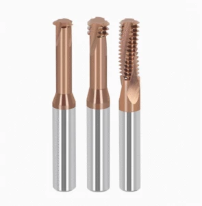
Practical Differences Between Thread Milling Toolpaths and Single-Point Threading Toolpaths
When thread profiles develop rough flanks or pitch diameter drift despite optimal speeds and feeds, the motion trajectory is usually to blame. For internal features, tool entry style, helical direction, and lead-out arcs dictate dimensional stability. That is why our CNC engineers treat the thread milling toolpath as a primary control variable rather than focusing solely on cutting tools.
A clean path eliminates chatter, minimizes radial deflection, and simplifies offset adjustments during production. Conversely, a flawed trajectory causes crest burrs and profile distortion even with premium coated carbide. In deep-hole threads or hardened alloys, always audit your roll-in arcs and radial stepovers before arbitrarily altering spindle RPM or surface footage.
How Thread Milling Toolpaths Affect Thread Dimensions and Profile Integrity
We recently resolved pitch diameter fluctuations on high-precision internal threads where tooling and machine backlash showed zero faults. Program simulation revealed an abrupt straight radial plunge that shock-loaded the tool tip upon entry. Transitioning to a smooth, tangential roll-in arc within the thread milling toolpath stabilized pitch dimensions across the entire batch.
Controlling the tool center trajectory prevents flank tearing and uneven thread crests. Dividing cuts into distinct roughing passes and a light spring pass isolates dimensional sizing from heavy chip loads. When flank roughness appears, inspect radial engagement and exit transitions rather than indexing carbide inserts prematurely.
Adjusting Thread Milling Toolpaths via Helical Interpolation
Helical interpolation requires precise synchronization between circular XY motion and linear Z-axis pitch travel. In deep holes or hardened alloys, long overhang amplifies micro-vibrations during this continuous spiral motion. Any interpolation lag or servo mismatch immediately leaves periodic chatter marks across both thread flanks.
Dial in critical tolerances by running conservative parameters on the first article, then compensating radial offsets from physical gauge readings. If pitch diameters measure oversized, verify toolholder runout and programmed radius before altering feeds. Fine-tuning a programmed thread milling toolpath with dedicated finish offsets ensures predictable, repeatable hole-to-hole sizing.
Differences Between Multi-Pass Single-Point Threading and Multi-Pass Thread Milling
In multi-pass single-point threading, the complete thread form develops progressively from repeated axial passes along a fixed lathe profile. Any insert wear, thermal growth, or tool pressure from early passes alters cutting dynamics on subsequent passes. On materials exceeding HRC60, this cumulative tool load quickly degrades the thread root radius and crest symmetry.
By contrast, multi-pass thread milling controls chip removal through radial stepovers while the cutter rotates along a helical path. Single-point turning relies entirely on tool-tip form integrity, whereas thread milling balances tool center coordinates with radial depth of cut. Optimizing a multi-pass thread milling toolpath against single-point turning requires calculating chip volume per pass rather than simply counting machine cycles.
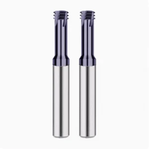
Thread Milling Speed and Feed: Parameter Adjustments for Hardened Steel Machining
Reusing standard speeds and feeds on hardened mold steels exceeding HRC60 causes micro-chipping, harmonic chatter, and rapid pitch taper. Rather than chasing arbitrary surface footage, we balance workpiece hardness, gauge length, core diameter, and machine rigidity. Finding the optimal thread milling speed and feed demands responsive parameter adjustments based on real-time cutting performance.
In the HRC62–HRC65 range, we evaluate surface feet per minute (SFM), feed per tooth (chip load), and radial engagement simultaneously. High-pitched spindle squeal or torn thread flanks immediately signal excessive cutting resistance or tool deflection. We always stabilize instantaneous cutting forces first before gradually ramping cycle times for series production.
How We Adjust Thread Milling Speed and Feed for HRC60–65 Materials
On HRC60–62 die components, drastically cutting RPM often accelerates rubbing rather than extending tool life. Instead of dropping surface footage, we reduce radial stepovers and program smooth tangential lead-ins to control instantaneous chip thickness. Dialing in a stable thread milling speed and feed requires logging edge wear progression after every single part.
When milling HRC65 alloys, calculate feed rates based on effective cutting diameter and internal helical arc adjustments. Long tool overhang combined with excessive chip load triggers severe harmonic chatter and destroys solid carbide flutes. We adjust feeds incrementally based on spindle load readouts, audible harmonics, and physical thread flank inspection.
Impact of Thread Milling Speed and Feed on Tool Wear and Thread Surface Quality
Excessive cutting pressure induces micro-chipping along the carbide crest, rapidly showing up as flank burrs and pitch diameter drift. Conversely, running excessively conservative feeds causes rubbing, heat concentration, and severe work hardening inside the hole. Balancing your thread milling speed and feed ensures clean shearing action while protecting delicate thread-crest profiles.
In hardened alloys, continuous chip evacuation via high-pressure dry air is critical to prevent recutting chips. If the first thread passes inspection but subsequent parts exhibit torn flanks, inspect edge wear before altering spindle RPM. Stable cutting parameters maintain a uniform, mirror-like flank finish without dimensional shifts over long production runs.
Differences in Feed and Cutting Parameters Between Single-Point Threading and Thread Milling
Lathe-based threading locks axial feed directly to lead pitch, shaping the profile through sequential depth passes. Helical milling, however, requires calculating internal circular compensation to maintain an accurate feed per tooth at the cutting radius. Because cutting mechanics differ entirely, translating lathe feeds into a thread milling speed and feed setup leads to catastrophic tool breakage.
In high-hardness alloys, multi-tooth milling dramatically lowers tool pressure per edge compared to single-point lathe profiling. We calculate radial engagement based on hole diameter, tool diameter, and flute count, followed by physical trial cuts. This methodical engineering approach ensures repeatable pitch tolerances and predictable carbide tool life across large production batches.

Carbide Thread Mill Tool Life vs Single-Point Threading Tool Life
Counting finished holes alone is an unreliable way to quantify tool longevity in hard milling. On HRC 60–62 mold steels, a tool often runs cleanly for dozens of holes before micro-burrs appear and pitch diameters drift toward the upper tolerance limit. Comparing carbide thread mill tool life vs single-point threading tool life requires tracking edge wear progression rather than relying on an arbitrary part counter.
Pulling a tool too early wastes valuable carbide, while running it too long risks scrapping expensive mold cores. We evaluate true tool endurance through dimensional stability, flank surface finish, and cutting acoustic feedback. A predictable, repeatable wear curve is the only reliable metric for keeping tight tolerances across high-volume production runs.
How We Determine if Carbide Thread Mill Tool Life Is at an Optimal Level
On the shop floor, we track dimensional drift against cutting edge degradation across scheduled inspection intervals. When benchmarking carbide thread mill tool life, we inspect for abrasive flank wear, micro-chipping, and notch wear under magnification. Slight surface discoloration alone does not signal failure if pitch diameters and Go/No-Go gauges remain within blueprint tolerances.
However, when pitch diameters approach the upper tolerance band and surface roughness spikes, we replace the cutter immediately. In hardened alloys, tool failure rarely happens as catastrophic breakage; it shows up as gradual dimensional drift and flank tearing. Swapping tools at the onset of profile degradation protects part quality and prevents costly rework.
Actual Wear Patterns on HRC65 Thread Mills During Continuous Threading
Machining hardened steels up to HRC65 rarely distributes cutting loads uniformly across every flute. In deep holes, extended overhang combined with chip packing concentrates bending moments on the leading cutting teeth. When inspecting solid carbide tools, we evaluate the leading edge, thread crest radius, and corner transition where chipping typically originates.
If thread quality degrades between the hole entrance and the bottom, inspect radial tool deflection and effective flute engagement. In our experience, excessive tool overhang reduces structural rigidity, causing harmonic chatter and taper even with undamaged tools. Resolving these taper errors requires verifying gauge length, spindle runout, and radial chip loads before blaming the tool substrate.
How Cutting Parameters and Chip Evacuation Affect Carbide Thread Mill Tool Life
Workpiece hardness is only one factor governing edge retention during continuous machining. Aggressive feed per tooth causes cutting edge micro-chipping, while overly conservative chip loads generate friction and severe work hardening. Maximizing carbide thread mill tool life requires balancing surface speed and radial stepover based on real-time cutting edge wear patterns.
Poor chip evacuation silently destroys solid carbide flutes in deep blind holes. When micro-chips cannot escape, the tool recuts hardened swarf, inflicting rapid abrasive wear and edge chipping. If tool life drops sharply in deeper threads under identical parameters, verify high-pressure dry air delivery and entry toolpaths before altering speeds and feeds.
Differences in Wear Patterns Between Single-Point Threading Inserts and Thread Mills
In single-point threading, a single insert tip shapes the complete thread profile across successive lathe passes. Tip degradation immediately translates into crest deformation, pitch diameter drift, and severe flank burrs. Because every pass rubs the same worn insert nose across hard steel, edge breakdown accelerates rapidly once micro-chipping begins.
Conversely, multi-flute thread mills distribute cutting forces across multiple teeth and allow pitch diameter adjustments via CNC radial offsets. Tracking edge wear, pitch stability, and first-part repeatability after tool changes reveals true performance differences. Selecting between carbide thread mill tool life vs single-point threading tool life ultimately hinges on hole geometry, machine rigidity, and process reliability.
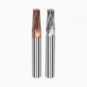
Thread Milling Cycle Time vs Single-Point Threading Cycle Time
Machinists often assume thread milling is inherently slower than single-point turning due to complex interpolation toolpaths, or that cheap turning inserts guarantee lower operational costs. However, evaluating thread milling cycle time vs single-point threading cycle time requires measuring floor-to-floor time rather than simulated cut seconds. In-process inspection, offset adjustments, and tool-change downtime drastically alter actual part costs.
To accurately compare cycle efficiency, we isolate rapid positioning, arc-in moves, helical revolutions, and tool retracts across entire production batches. Focusing solely on single-hole execution ignores cumulative downtime caused by edge wear and frequent offset tweaks. A reliable process benchmark always measures consistent part throughput over theoretical spindle cycle speeds.
How We Break Down Thread Milling Cycle Time
When calculating net thread milling cycle time, we separate rapid transit, radial engagement, helical interpolation, spring passes, and clearance retracts. In deep-hole threads, non-cutting axial travel down the hole bore often consumes more time than the actual helical cut. Isolating these motions reveals whether cycle bottlenecks stem from conservative cutting feeds or inefficient clearance plane programming.
We recommend tracking two distinct metrics: pure cut time and overall floor-to-floor cycle time. Pure cut time reflects chip-making efficiency, but total cycle time captures part probing, manual gauge checks, and tool wear compensation. Comparing methods with consistent time-tracking standards prevents skewed data and ensures accurate machining cost estimates.
How Thread Length, Hole Diameter, and Pitch Affect Thread Milling Cycle Time
Thread length, major diameter, and thread pitch dictate total path length and axial travel per revolution. Hole diameter directly alters the circumference of the tool-center path, while pitch determines axial advance per spiral rotation. Consequently, even for identical M8 threads, varying engagement depths and pitch specifications will yield drastically different cycle times.
In deep holes or hardened alloys, pushing radial depth of cut to shorten cycle time inevitably causes tool deflection and chatter. The resulting profile taper forces additional spring passes, negating any initial time savings. To lower your thread milling cycle time, optimize toolpath clearance moves first before aggressively ramping radial chip loads.
Cycle Time Differences Between Thread Milling and Single-Point Threading in Batch Production
In batch manufacturing, evaluating thread milling cycle time vs single-point threading cycle time hinges on tool change intervals and offset frequency. Single-point turning may cycle faster on a single part, but insert tip breakdown in hardened steel demands frequent stoppages for dimensional compensation. Over a 500-piece run, cumulative setup downtime can quickly eliminate the lathe’s speed advantage.
Conversely, multi-tooth thread mills maintain pitch diameter stability over longer runs, delivering a predictable production rhythm. However, thread size, workpiece hardness, and machine capabilities still dictate the optimal method. We recommend running a small pilot batch to log real-time cutting duration, gauge check intervals, and tool-wear downtime.
Why Comparing Tool Prices Alone Cannot Determine Actual Machining Costs
Choosing single-point turning solely because indexable inserts cost less upfront than solid carbide thread mills is a common operational mistake. The true financial metric is the net machining cost per qualified threaded part, not purchase order tool prices. This total cost combines cycle time, machine burden rates, tool-change downtime, inspection intervals, and scrapped-part risks.
Factoring in carbide tool life and process stability often proves that higher upfront tooling pays for itself through unattended reliability and scrap reduction. Conversely, for low-volume runs or simple external threads, basic single-point tooling remains the most economical path. Our shop floor decisions always focus on lowest cost per acceptable part rather than the initial tool price tag.

HRC65 Thread Milling vs Single-Point Threading for Hardened Steel
When threading high-hardness mold steels, maintaining dimensional accuracy and flank integrity across production is the real test. We once solved an HRC62 mold core failure where initial parts passed inspection, but micro-chipping quickly caused severe pitch drift. Weighing HRC65 thread milling vs single-point threading for hardened steel requires auditing tool deflection, machine rigidity, and chip clearing rather than assuming one process universally dominates.
We never switch machining methods purely based on a Rockwell hardness rating. Instead, we evaluate thread pitch, depth-to-diameter ratios, production volume, and spindle load dynamics. Above HRC60, cutting forces, localized heat, and harmonic vibration interact aggressively. Dialing in a stable setup demands tracking real-time carbide wear patterns rather than applying standard alloy steel feeds and speeds.
Key Machining Risks for HRC62–HRC65 Hardened Steel
Machining HRC62–HRC65 tool steels starts with checking core hardness uniformity, since localized heat-treat variations cause sudden cutting force spikes. Extended tool overhang, weak fixturing, or spindle runout over 0.0002″ will instantly cause chatter and edge chipping. When threading hardened dies, stabilize dynamic rigidity first before attempting to raise surface footage.
Chip evacuation poses another critical failure point in deep blind holes. While hardened chips break short, trapped swarf re-enters the cut zone, inducing thermal shock and catastrophic carbide fracture. When using HRC65 thread milling tools, use high-pressure dry air blasts and smooth roll-in paths to flush chips and prevent micro-welding on the flutes.
Key Control Points for Thread Milling Hardened Steel (HRC65)
Running solid carbide tools in HRC65 die steels demands short gauge lengths and minimal toolholder runout. Excessive overhang creates micro-deflections under radial cutting pressure, leading to pitch taper and irregular crest chipping. If chatter appears, shortening the tool projection and tightening holder concentricity works far better than simply backing off the feed rate.
Optimize cutting parameters incrementally by monitoring spindle load meters, acoustic pitch, and thread flank sheen. When dialing in HRC65 thread milling, listen for high-frequency squeal during entry arcs, which signals excessive tool engagement. Identifying subtle edge degradation during first-article inspection prevents running entire batches out of pitch tolerance.
Addressing Chipping, Chatter, and Dimensional Drift When Thread Milling Hardened Steel
When carbide teeth chip in hard steels, isolate the mechanical failure point before blaming the tool substrate. Chipping localized at hole entry points indicates excessive radial shock, which requires smoothing the helical roll-in trajectory. If abrasive wear spans the entire profile, dial back surface footage and check radial stepovers to mitigate excessive cutting heat.
Chatter marks on thread flanks point directly to harmonic vibration and improper radial depths of cut. As cutting edges wear, effective tool diameter shrinks, gradually drifting the pitch diameter toward the upper tolerance limit. Track Go/No-Go gauge drag across scheduled intervals so you can compensate diameter offsets before threads fall out of spec.
When Single-Point Threading Remains Suitable for Hardened Steel
Hardened alloys do not automatically rule out lathe operations if your machine tool and chucking setup offer high static rigidity. For external threads, large-diameter bores, or consistent low-volume batches, indexable turning inserts remain practical and cost-effective. Sticking with proven turning operations avoids the programming, tooling, and prove-out costs of transitioning to a milling center.
However, deep internal holes and tight pitch tolerances tilt the balance back toward dedicated thread mills. Evaluating HRC65 thread milling vs single-point threading for hardened steel comes down to part geometry, machine capabilities, and scrap risk. Verifying real-world trial cuts ensures you select the process that guarantees repeatable dimensional control on your shop floor.

Thread Milling vs Single Point Threading: Choosing the Right Method Based on Application Conditions
A threading process that excels on one component can easily fail on another. Choosing between thread milling vs single point threading requires evaluating hole diameter, thread depth, pitch tolerance, batch volume, machine rigidity, and tool overhang. In hardened alloys (HRC 60–65), cutting forces, harmonic vibration, and tool wear interact constantly, making a holistic setup review essential.
Before selecting tooling, define your actual production constraints: Are you cutting deep blind holes or shallow through-features? What are the true pitch diameter tolerances, and is the part fixtured on a lathe or a machining center? Answering these operational questions first prevents costly tooling mistakes and sets clear criteria for process selection.
Process Selection for Small-Diameter and Deep-Hole Threading
Small-diameter, deep-hole threads are exceptionally sensitive to tool overhang and structural rigidity. Long gauge lengths amplify radial deflection, increasing the risk of harmonic chatter and cutting-edge micro-chipping in hardened alloys. We inspect toolholder runout, verify air-blast chip clearing, and program gentle tangential lead-in arcs before cutting the first hole.
When troubleshooting small internal threads, separate tool wear issues from vibration problems. If thread flanks tear, shorten the tool projection and improve setup rigidity before tweaking feeds. While solid carbide cutters excel in hardened tool steels, process success ultimately depends on machine motion accuracy and physical thread geometry.
Thread Milling vs. Single-Point Threading for High-Precision Threads
In high-precision applications, process capability means holding dimensional repeatability throughout an entire production shift, not just passing first-article inspection. Evaluating thread milling vs single-point threading requires tracking pitch diameter stability, flank roughness, and tool wear over hundreds of parts. If pitch diameters drift as tools wear, optimize toolpaths and rigidity instead of endlessly updating wear offsets.
For internal threads with tight tolerances, thread mills allow independent pitch diameter adjustments via CNC cutter compensation. This gives milling centers a distinct edge over turning inserts when correcting for micro-deflection. However, if your existing lathe setup consistently passes Go/No-Go gauges, keep the proven process running and avoid unnecessary tooling expenses.
Process Selection for Small-Batch, Multi-Specification Threading
Short runs with mixed thread sizes shift the operational focus toward setup times and magazine capacity. One solid carbide thread mill can generate various diameters sharing the same pitch, substantially reducing your active tool inventory and setup overhead. Conversely, if thread specs are standardized and single-point turning tools are already dialed in, retooling adds unnecessary expense.
To optimize high-mix setups, audit your active tool count, changeover frequency, and programming overhead. Compare workpiece hardness, hole depth, and fixturing across parts to identify where standardized thread mills can consolidate operations. In hardened steels, evaluate repeatable dimensional control and edge retention rather than the speed of a single cycle.
Evaluating Processes by Balancing Thread Milling Cycle Time and Tool Life in Mass Production
In mass production, true efficiency depends on combining thread milling cycle time with reliable carbide thread mill tool life. Single-point turning may cycle faster on a single hole, but frequent insert changes and offset adjustments quickly ruin overall throughput. Unplanned downtime and scrapped components often outweigh minor gains in programmed feed rates.
Track floor-to-floor cycle times, qualified parts per cutting edge, and gauge check intervals across extended runs. Count only parts that meet print tolerances, as a tool is functionally dead the moment pitch diameters drift out of spec. Real machining profitability depends on the lowest total cost per qualified thread, not just the purchase price of the cutter.

Thread Milling vs Single Point Threading: Shop Floor FAQs
Threading issues rarely emerge during first-article cuts. Instead, dimensional drift, uneven tool wear, and cycle bottlenecks surface during continuous batch production. When comparing thread milling vs single point threading, process success depends on matching workpiece hardness, thread size, machine rigidity, and batch volume.
This balance is critical when machining hardened steels. A setup that holds tolerance on a prototype can fail in production if cutting forces fluctuate. Resolving these issues requires auditing dynamic variables rather than declaring one method universally superior.
Is Thread Milling More Accurate Than Single Point Threading?
Neither process is inherently more accurate. While thread milling allows independent pitch diameter adjustments via CNC offsets, excessive tool runout or servo lag will quickly produce out-of-spec parts. Conversely, a rigid lathe running single point threading can reliably hold tight tolerances on external and standard diameters.
We evaluate process accuracy using continuous production data rather than initial test cuts. When controlling pitch diameter, flank finish, and profile symmetry, machine motion stability and cutting tool deflection dictate the final tolerance.
Can a HRC65 Thread Mill Machine Hardened Steel?
A dedicated HRC65 thread mill can reliably cut hardened mold steels when setup rigidity, tool overhang, and substrate coatings are fully aligned. While materials above HRC60 spike cutting resistance, stability depends on thread diameter, pitch, and depth-to-diameter ratios.
Never apply standard alloy steel parameters to HRC65 alloys. Run small-batch trial cuts, clear chips with high-pressure air, and monitor cutting edges under magnification. Gradually optimize parameters based on flank finish and spindle acoustic feedback.
How Does Thread Milling Toolpath Affect Thread Milling Tolerance?
Programmed toolpaths directly govern final dimensions. Sudden straight radial plunge entries shock the tool tip, causing deflection and tapered threads. Using a smooth tangential roll-in arc preserves edge sharpness and keeps the thread milling tolerance tightly controlled.
Separating heavy material removal from final sizing passes isolates deflection forces from the finished thread profile. If pitch errors or flank chatter appear at the hole entrance, audit the lead-in trajectory and toolholder runout before replacing the cutter.
How Do Thread Milling Speed and Feed Affect Tool Life?
Dialing in your thread milling speed and feed requires balancing thermal load against mechanical friction. Overly aggressive feeds trigger micro-chipping along the carbide crest, while excessively conservative parameters cause rubbing, heat buildup, and rapid work hardening.
On HRC60–65 alloys, calculate chip loads from effective internal cutting radii. Start with conservative stepovers, inspect edge wear progression after each part, and adjust parameters based on spindle load and cutting acoustics.
How Long Should a Carbide Thread Mill Tool Life Last?
We define carbide thread mill tool life by dimensional capability rather than raw hole counts. Thread depth, alloy hardness, tool overhang, and chip packing all dictate when an edge degrades.
When pitch diameters drift toward upper tolerance limits or flank burrs appear, replace the cutter immediately. Running worn tools until catastrophic breakage risks scrapping expensive components.
Is Thread Milling Cycle Time Longer Than Single Point Threading?
Evaluating thread milling cycle time requires measuring floor-to-floor throughput, not just programmed spindle time. While single-point lathe turning executes fast single cuts, frequent insert wear and offset adjustments create cumulative downtime.
Thread milling often yields faster net production on high-mix setups, deep internal holes, or hard steels by stabilizing dimensions and minimizing manual gauge checks. Benchmark both methods using identical overall timing standards.
When Should We Use Thread Milling Instead of Single Point Threading?
Switch to thread milling for small-diameter deep holes, blind holes requiring full threads to the bottom, multi-pitch parts, and materials exceeding HRC60. If your existing turning operation suffers from chatter, chip packing, or rapid insert breakdown, milling is the better alternative.
However, keep single point threading if your lathe setup reliably passes Go/No-Go inspection and meets cost targets. Retooling is unnecessary if the current process is stable and cost-effective.