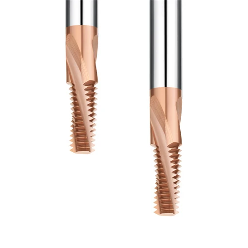

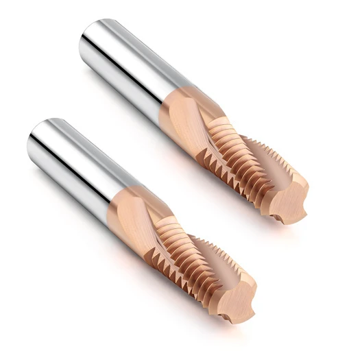
Last month, a mold shop in Stuttgart sent a scrapped ejector guide pin to our lab. The part was vacuum-hardened AISI D2 tool steel (1.2379) at 62 HRC with an M16×1.5 external thread. The shop tried single-point threading on a lathe. They shattered three coated inserts in a row. After 14 hours of upstream machining, the part was ruined by severe chatter, crest tearing, and an out-of-spec pitch diameter.
Over the past 16 years, we have tackled hundreds of identical failures while supporting precision machine shops across Europe and North America. When facing 55–65 HRC steels, many machinists instinctively try low-speed hard turning or fall back on slow, costly EDM. But hard turning leaves zero margin for spindle deflection. Meanwhile, EDM electrode wear frequently distorts thread flank angles, causing immediate “go/no-go” gauge rejections.
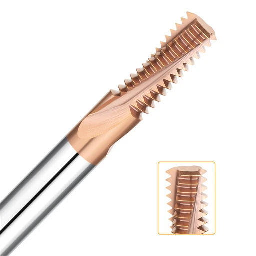
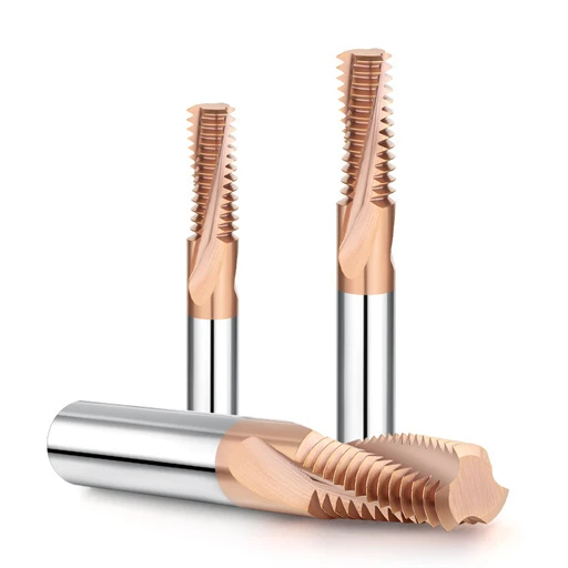
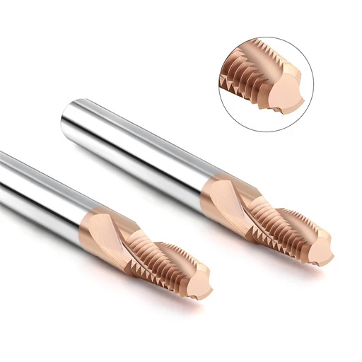
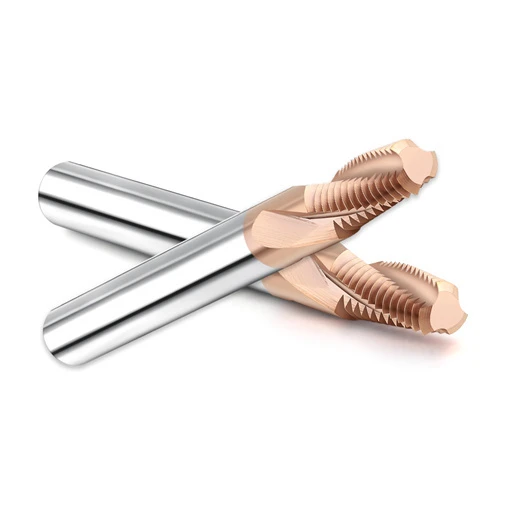
This is why CNC external thread milling remains our primary choice for hardened steels. By distributing loads across cutting flutes and leveraging interrupted cuts for rapid cooling, a dedicated solid carbide external thread milling cutter easily holds 6g or 4h tolerances. But you cannot run hardened steel like pre-hardened 4140 or P20. At 60+ HRC, ductile chip formation disappears. Without the right approach, massive radial deflection causes cutting edge micro-chipping within milliseconds.
In this guide, we bypass basic textbook definitions to share hard-won shop floor data. We cover external thread milling tools geometry, deflection-free CNC thread milling toolpath techniques, and real-world feeds and speeds. When cutting threads on 60 HRC shafts, do you also struggle with chipped crests or taper errors where the gauge binds halfway down?

Why Are Workshops Moving Away from Single-Point Threading Toward CNC External Thread Milling?
Single-point threading on a turning center seems straightforward, but cutting forces spike exponentially past 55 HRC. Machinists often drop surface speed and take 15 to 20 passes to preserve the insert. However, continuous contact traps extreme friction heat at the microscopic nose radius. Under heavy thermal load and abrasive carbides, the edge micro-chips after just one or two parts. A chipped edge on the final pass scraps the entire workpiece.
Switching to CNC external thread milling is a pragmatic process choice. Milling is fundamentally an interrupted cut. Each tooth engages the material for only a few milliseconds, giving the edge and coating ample air time to cool. Crucially, milling breaks heavy continuous cutting forces into tiny, manageable chips. This gives us tight control over size, finish, and pitch diameter consistency.
From Turning-Induced Chipping to CNC External Thread Milling: Field Lessons on 55–65 HRC Spools
We saw this firsthand on a batch of 60 HRC 440C stainless hydraulic spools with M14×1 external threads. The shop was single-point turning with expensive CBN inserts. Every time the insert crossed the radial cross-drilled oil ports, the interrupted edge impact hammered the tip. The operator had to replace inserts every 4 to 5 parts. Chipped edges tore the thread flanks, generating heavy burrs and failing thread ring inspection.
We moved the job to a 4-axis machining center using CNC external thread milling. Although the cycle time was 8 seconds longer per part, usable tool life jumped from 5 pieces to over 180 pieces per tool. For any production manager facing tight delivery schedules, this reliability is priceless. Predictable, lights-out machining beats an unstable, aggressive turning setup every single time.
High-Hardness Threading Bottlenecks: Thin Walls, Relief Undercuts, and Thread Cutting Tools Limits
Thin-walled hollow shafts present severe rigidity limits. Traditional thread cutting tools exert continuous radial tool pressure against the part. On a hardened sleeve with a 2 mm wall, this pressure creates elastic deflection during the pass. The outside diameter might measure fine, but stress relief leaves a saddle-shaped pitch diameter that binds a 6g thread ring gauge dead in the center.
Thread relief undercuts create another major failure point. Hard turning requires an undercut at least 1.5 to 2 times the thread pitch to let the slide decelerate safely. Without that gap, the insert crashes into the shoulder. Thread milling uses helical interpolation without spindle braking. You can safely cut within half a pitch of a shoulder without risking chipped corners.
Machine Rigidity and Spindle Requirements: High-Speed Machining Thresholds for Hardened Steel
Do not run hardened steel thread milling on an unverified setup. When evaluating customer processes, we inspect spindle taper fit and tool holder rigidity first. Machining hard materials requires high spindle speeds and shallow cuts. Your CNC control needs fast look-ahead processing. Any servo lag or stutter during circular interpolation causes an instant force spike that snaps small carbide teeth.
Tool runout is your most critical shop floor threshold. Total radial runout at the tool tip must stay below 0.003 mm (TIR). Hardened steel does not forgive uneven chip loads. A runout of 0.01 mm might pass in soft steel, but at 62 HRC, it forces one tooth to take the entire cut. Always use high-rigidity hydraulic chucks or shrink-fit holders, paired with a clean, high-pressure air blast to clear abrasive dust.
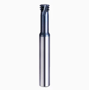
Tool Substrate and Geometry: Selection Criteria for Solid Carbide External Thread Milling Cutters in High-Hardness Applications
Standard carbide blanks break down fast between 55 and 65 HRC. Many buyers rely solely on catalog hardness ratings. They ignore critical transverse rupture strength and grain boundary cohesion under heavy radial loads. Our shop tests show that cutting hardened steel creates high-frequency micro-impacts. If substrate toughness is low, edges do not wear gradually. Instead, they shatter along crystal boundaries instantly.
Selecting a proper solid carbide external thread milling cutter requires balancing ultra-fine grain structure with section modulus. The core thickness ratio, flute helix angle, and edge honing determine tool deflection under extreme push forces. If the core diameter is too thin, even the best coating cannot stop elastic bending during circular moves. That deflection destroys thread pitch roundness immediately.
Grain Size and Coating Performance: Anti-Spalling Solutions on HRC 65 Steels
Last year, a Swiss mold shop struggled milling 63 HRC AISI S7 cores. Standard TiAlN tools failed after three parts. At this hardness, localized interface heat easily tops 800°C. Massive cutting forces combined with thermal expansion mismatches between carbide and coating caused the film to flake off. Once exposed, the bare tungsten substrate eroded into deep gouges from hard carbides.
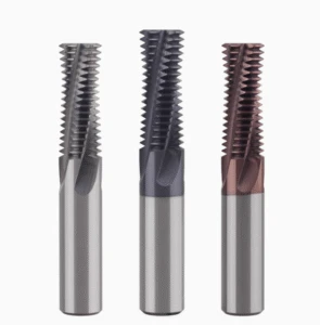
We solved this by engineering a dedicated solid carbide external thread milling cutter on a sub-micron 0.2–0.4 μm substrate. We paired it with an AlTiSiN or high-adhesion AlCrN nanocomposite coating. The high-aluminum surface forms a dense self-passivating alumina barrier at extreme temperatures. Meanwhile, internal nanolayers absorb cyclic thermal shocks. This stops micro-crack propagation and prevents coating delamination.
Selecting Tooth Profiles: Single-Tooth, Multi-Tooth, or Staggered Thread Mill Tools
Machinists often ask if full-profile multi-flute tools are always faster. It depends entirely on setup rigidity. We watched a shop try a full-profile tool on a slender 58 HRC shaft. The spindle squealed violently within half a turn. Engaging all teeth at once spikes the contact arc and instantaneous radial cutting pressure. On long overhangs, the tool deflects away, leaving severe front-to-back taper.
When selecting thread mill tools for high-hardness setups, balance contact area against chip room. For thin walls or length-to-diameter ratios over 3:1, choose single-profile or three-tooth cutters. They take more passes, but the tiny contact area cuts radial pressure to near zero. For rigid, stubby parts, run multi-flute cutters with unequal flute indexing to break harmonics and clear fine chips easily.
Tool Clamping and Dynamic Balance: Ditching Standard ER Collets for Hydraulic or Shrink-Fit Holders
The most common shop floor mistake is putting a precision carbide tool into a worn ER collet. Segmented spring collets easily slip into micron-level angular tilt. In 60+ HRC steels, runout of just 0.008 mm forces one tooth to take the entire cut load. That single high tooth overloads and chips within microseconds. Once one tooth breaks, the remaining flutes snap in quick succession.
For tight-tolerance work in hardened steel, we require shrink-fit holders or hydraulic chucks. Shrink-fit tooling gives 360-degree symmetrical clamping and holds total indicated runout (TIR) under 0.003 mm. Hydraulic holders provide internal fluid damping to soak up interrupted cut chatter. Stable concentricity ensures your external thread milling tools wear evenly instead of breaking on entry.
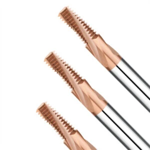
CNC Thread Milling Toolpath and Entry Strategies for Hardened Steel
Taking full thread depth in one pass works in mild steel, but it destroys tools in 55–65 HRC stock. Hardened steel lacks ductility and exerts brutal compressive resistance against the tool tip. Without proper force relief in the program, tool overhang deflects by several microns. During circular interpolation, that flex produces chatter and wavy flanks. In severe cases, fatigue loads snap the thread crests off.
A reliable CNC thread milling toolpath breaks extreme cutting forces into gentle, manageable passes. When troubleshooting for clients, we check toolpath entry arcs and step-over depths before touching spindle speeds. Keeping tool engagement angles within a narrow window preserves the thread flank angle. It also eliminates the micro-chipping that ruins finished parts.
Eliminating Deflection and Taper: Radial Multi-Pass Strategies for Hardened Shafts
On 62 HRC M24 guide pillars, ring gauges often seize halfway down the thread length. Three-wire measurements usually reveal a 0.015 to 0.025 mm pitch diameter taper toward the shoulder. This is caused by radial tool deflection pushing away from the cut. Splitting the cut into two equal passes fails because chip load on the second pass remains high enough to cause push-off.
We eliminate this taper by programming a decreasing radial CNC thread milling toolpath. We divide depth of cut across three or four steps: rough out 55%, semi-finish 30%, and drop the finish pass to 0.03–0.05 mm before running a spring pass at final size. Decreasing radial load drops tool deflection to zero on the final lap, ensuring a straight, non-tapered pitch diameter.
Preventing Entry Chipping: Why Use 90°/180° Helical Arc Lead-In Over Straight Plunging
Straight G01 linear plunging into a 60 HRC outer diameter causes instant shock. Chip thickness jumps from zero to maximum in a fraction of a millisecond. Slamming a sharp carbide tip straight into hardened steel leaves visible dwell marks. More importantly, that sudden mechanical spike micro-chips the delicate edge radius on the very first touch.
Our programs always use a 90° or 180° helical arc lead-in and lead-out. By descending along the Z-axis while rolling tangentially into the part diameter, chip load builds smoothly from true zero to target thickness. This spreads contact forces evenly across the tool edge. Tangential arc exits prevent dwell gouges, protecting the profile from start to finish.
Climb Milling vs. Conventional Milling: Mechanics of Thick-to-Thin Chip Formation
We hear ongoing debates about milling direction, but hardened steel demands climb milling exclusively. Conventional milling forces the edge to rub at zero chip thickness before biting in. Against a 60 HRC surface, the tool skids under heavy friction. This creates localized heat over 1,000°C and work-hardens the surface layer, dulling the flank face in minutes.
Climb milling starts with maximum chip thickness and tapers down to zero as the tooth exits. This clean thick-to-thin cut carries friction heat away inside the flying chip, protecting the tool substrate. The downward cutting force also helps seat the workpiece securely against the spindle center. With good machine backlash control, climb milling guarantees crisp, burr-free thread flanks.
Cutting Tips from the Shop Floor: Practical Parameters and Machine Tuning
Relying on speeds printed on the tool box is a recipe for broken carbide in 55–65 HRC steels. Catalog charts assume rigid test benches and zero tool overhang. Real shops fight spindle harmonics, part overhang, and fixture flex. Dialing in parameters on hard steel is an empirical process. You must balance frictional heat, tool deflection, and thread surface finish.
Our primary rule for cutting tips from the shop floor is simple: lock down stability first, then push for cycle time. A broken tool scraps an expensive part that already carries hours of machining time. Listen to the pitch of the cut outside the enclosure, run careful trial cuts, and dial out process variables systematically before hitting cycle start on a production run.
H3: Balancing Hardened Steel Parameters: Surface Speed (Vc) vs Feed per Tooth (fz)
Surface speed (Vc) controls tool life. As material hardness climbs past 55 HRC, you must pull speed back sharply. Run 60–80 m/min dry for 55–60 HRC steels, and drop down to 40–55 m/min above 62 HRC. Excessive surface speed drives cutting zone temperatures above 900°C. This diffuses the carbide cobalt binder and flashes the coating off the flank face in seconds.
However, never choke the feed per tooth (fz) out of fear. Setting fz below 0.005 mm per tooth is a common trap. When feed drops below the honed edge radius, the teeth rub and burnish instead of cutting. This work-hardens the surface and destroys clearance flanks. Keep your feed strictly between 0.015 and 0.035 mm per tooth so every tooth cuts clean, crisp chips.
Air Blast, MQL, or Flood Coolant? Chip Evacuation Strategies for External Thread Milling in Hardened Steel
Whether to run wet or dry is heavily debated. On a horizontal mill cutting 60 HRC shafts, flood coolant caused vertical thermal cracks across tool flutes within three parts. The rapid cycling between 800°C cuts and cold emulsion causes severe thermal shock. This shock fractures the carbide matrix and shatters delicate thread-form crests.
When performing external thread milling in hardened steel, run a continuous, dry air blast at 6–8 bar directly at the cut. Air eliminates thermal fatigue and blows abrasive, powdery chips out of the thread roots before they get recut. If you are machining sticky high-alloy mold steels, use Minimum Quantity Lubrication (MQL) with vegetable ester oil to reduce friction without thermal shock.
H3: The First-Cut Compensation Method: Using Wear Offsets to Eliminate Pitch Diameter Spring-Back
High elastic modulus causes hardened steels to push back, leaving the pitch diameter oversized on the first part. Inexperienced operators often panic when the ring gauge binds and immediately rewrite the CAM geometry. This burns setup time and creates dimensional headaches when swapping to a new tool later.
Use your CNC controller wear offset table instead. Set an initial radial wear offset of +0.03 to +0.05 mm before taking the first pass. Measure the actual pitch diameter with a thread micrometer or the three-wire method. Step down the wear offset value in the control and take a clean spring pass. This dial-in method absorbs tool flex and machine compliance without altering your master NC code.

Troubleshooting Common Workshop Issues: Chipped Edges and Thread Inaccuracy with External Thread Mills
Small process errors create glaring defects in hardened materials. When a thread ring gauge binds or crests chip, operators reflexively blame the carbide cutter. But hardened steel milling is an unforgiving system. Spindle rigidity, toolholder grip, interpolation stability, and chip clearing all interact. A variance of just 3 microns in any of these factors will scrap the component.
Diagnosing an external thread mill requires reading the wear patterns on the tool like a road map. Micro-chipping, burrs, and tapered pitch diameters always leave clear mechanical clues. Inspecting the tool under a 20x loupe and checking chip morphology will quickly pinpoint whether your issue is mechanical shock, thermal breakdown, or part deflection.
Torn Thread Crests and Pitch Diameter Ovality: Spindle Thermal Drift and Tool Overhang
If you see torn crests or your three-wire pitch measurement shifts more than 0.015 mm around the diameter, inspect tool overhang first. Operators often choke up toolholders to clear clamps or part shoulders. Shank bending stiffness drops by the cube of overhang length. Excessive stick-out with an external thread mill creates harmonic chatter that cuts oval threads.
If pitch diameter drifts between a cold morning startup and mid-afternoon, check machine spindle thermal growth. Thermal expansion changes the tool position during helical interpolation. Keep tool stick-out under 3 times the shank diameter, switch to heavy-core stepped cutters, and let your spindle warm up to thermal equilibrium before cutting tight-tolerance threads.
Chipping and Micro-Cracks at the Root: Eliminating Dwell Marks and Chip Recutting
If you spot shell-shaped micro-cracks along the thread root, inspect your code for corner deceleration or feed dwells. If a solid carbide tooth dwells against 60 HRC steel for even a fraction of a second, the rubbing heat spikes normal pressure. This stress concentration exceeds the tensile strength of the hard workpiece, fracturing the root geometry.
If fine chips clump together in the flutes, your air blast is misaligned. Hardened chips act like grinding grit inside the thread form. If chips are dragged back through the cut, the next tooth hits them at full speed. This double-impact load instantly chips the minor diameter of the part and shears teeth off the cutter.
Reading Flank Wear: Collaborating with Your External Thread Milling Tools Manufacturer
Standard catalog tools eventually hit physical limits in extreme workpiece conditions. If you run low-runout shrink holders, smooth arc lead-ins, and high-pressure air, yet experience edge flaking or pitch drift, standard geometries are no longer sufficient. It is time to review application data with your external thread milling tool engineering team.
If you are struggling with a difficult 60+ HRC alloy, thin-walled bores, or narrow thread reliefs, you can share your part drawings, material specs, and tool wear photos with us. We can evaluate your cutting forces and adjust micro-grain carbide cobalt levels, optimize edge hones, or apply custom nanocomposite coatings to stabilize your production run.