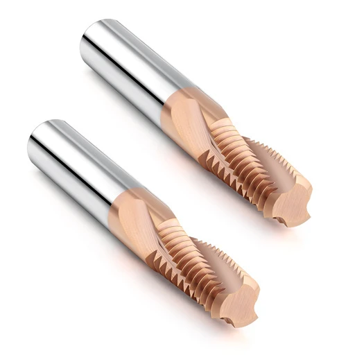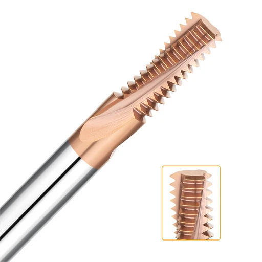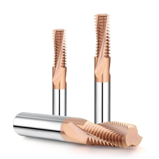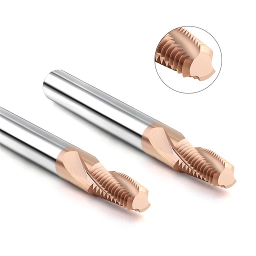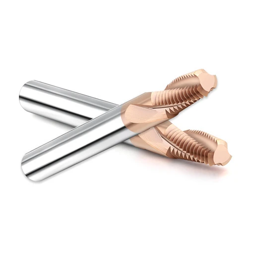

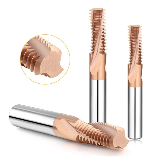
Last month, a long-standing partner—a precision injection mold shop in Stuttgart, Germany—sent us a video from their shop floor. A 5-axis machining center had triggered an emergency stop with a broken tool fragment wedged at the bottom of a hole. The workpiece was a D2 tool steel mold insert valued at tens of thousands of euros, hardened to HRC 64–65.
The job required machining an M6 standard-pitch thread at the bottom of a 4.5D blind hole. To bypass the extreme risk of tap breakage, the shop chose deep-hole internal thread milling. By the second part, the tool tip chipped from thermal fatigue caused by micro-vibrations and seized in the hole. The shop supervisor wrote to us: “We have already scrapped two solid-carbide tools. The pitch diameter taper is off by 0.03 mm—the no-go gauge enters the hole, but the go gauge jams halfway down.”
Over the past 16 years of tooling support across Europe and North America, we have seen this failure pattern repeatedly.
Many machinists assume they can lower the cutting speed and slowly “grind” threads into hardened steel using a standard coated tool. In deep-hole thread milling in HRC65 steel, the loss of tool rigidity makes this approach fail quickly:
-
Tapering from tool deflection: Beyond a 3.5D depth-to-diameter ratio, radial cutting forces bend a long reach thread mill, yielding an oversized entrance and a tight bottom.
-
Secondary cutting: Trapped micro-chips cannot escape closed blind holes. They crush against the flutes, causing severe edge chipping.
-
Thermal fracture: Standard coatings oxidize rapidly under the intense cutting heat of HRC65. Once the substrate is exposed, the teeth anneal and break in seconds.
Fixing this requires more than lowering feed rates. Predictable thread quality relies on a dedicated solid carbide thread mill for deep holes, radial multi-pass toolpaths, and strict dynamic runout control.
If your shop battles scrap rates on high-value hardened components during the final threading pass, how can you tune your tool geometry, helical paths, and radial offsets to bring your scrap rate to zero?

Failure Mechanisms and Operational Pain Points in Deep Hole Internal Thread Milling
Machining at HRC65 with conventional shallow-hole milling strategies leads straight to broken tooling. Once a blind hole reaches 3D to 5D depth, the cavity turns into an isolated thermal pocket. Shear heat cannot dissipate into the hard workpiece, so thermal spikes concentrate right on the micro-cutting edge. In our shop audits, early failure during deep hole internal thread milling rarely comes from gradual flank wear; it comes from thermomechanical shock triggering micro-fractures.
Machinists often get misled because the top two threads look clean on first inspection. Deeper down, the thread profile tears, chips out, or turns elliptical. Long reach amplifies dynamic vibration, toolholder runout, and chip pack. If one variable drifts, the cut slips from stable shear into destructive chatter. Mastering the physics inside this confined space is the only way to stop breaking tools and scrapping parts.
Tool Deflection, Tapering, and the Root Causes of Chatter in Long Reach Thread Milling
Static tool rigidity drops with the cube of the overhang length. When you hang a long reach thread mill out past 4D, periodic radial cutting forces deflect the slender neck. The tool pushes away from the cut, deflecting more the deeper it goes. On the coordinate measuring machine (CMM), this shows up as a classic reverse taper: open at the top, choked at the bottom.
Deflection also triggers high-frequency regenerative chatter. As the tooth exits and re-enters the cut, varying chip thickness creates self-excited vibrations that leave microscopic washboard marks on the thread flanks. Machinists often try to “push through the chatter” by increasing the feed. In HRC65 steel, higher chip loads spike radial force and snap the neck instantly. You cannot overpower the material; you have to manage deflection with multi-pass stepovers.
Common Scenarios for Chipping and Tool Breakage in D2 Tool Steel Thread Milling
When we run failure analysis on tools returned from D2 tool steel thread milling setups, the break almost always traces back to micro-chipping on the secondary flank. Hardened D2 contains clusters of hard, coarse eutectic chromium carbides. Hitting these abrasive carbides with a fine feed is like striking flint with a razor blade. The cyclical impact fatigues the PVD coating and micro-fractures the carbide substrate.
The highest risk occurs during tool entry and exit. Operators often plunge straight in radially or program a dwell at the bottom to “clean up” the thread root. In hardened D2, that sudden radial shock overloads the cutting edge, causing immediate micro-chipping. Once one tooth chips, the trailing tooth takes double the chip load. That triggers a rapid cascading failure where every tooth shears off, seizing the tool in the part.
The Impact of Poor Chip Evacuation: Secondary Cutting and Thread Pitch Diameter Deviations
Shops often spend hours tweaking spindle speeds while ignoring basic chip evacuation. In deep blind holes, chips cannot escape without high-pressure, coaxial blast air. Hardened micro-chips get trapped in the thread crests and crushed by the tool flutes on the next pass. This severe recutting scuffs the tool flanks, spikes cutting temperatures, and ruins the thread finish.
We ran a controlled test on an M6 deep-hole thread in hardened steel to measure this effect. With standard air flow, trapped chips caused pitch diameter variations over 0.045 mm—the “no-go” gauge entered the top, while the “go” gauge seized halfway down. Switching to coaxial high-pressure through-air with minimum quantity lubrication (MQL) evacuated chips instantly. Pitch diameter variation dropped to 0.012 mm with a clean surface finish, proving chip evacuation makes or breaks thread tolerance.
Design and Selection of Solid Carbide Thread Mills for Deep-Hole Machining of HRC65 Mold Steel
When cutting tool steel hardened past HRC60, standard tooling frequently shatters within the first two passes. In deep bores, flutes need chip clearance, but the tool neck demands maximum bending stiffness. Selecting the proper carbide thread mill for mold making means walking a tightrope between extreme abrasion resistance and structural impact toughness.
Our tooling audits in European injection and stamping mold shops show that success never comes from a single feature. It requires balancing sub-micron grain sizing, heat-resistant coatings, and a rigid neck taper. We often trade away theoretical cycle time to preserve edge integrity, because a chipped tooth in a deep blind hole scraps the entire insert.
Optimizing Substrate Grain Size and High-Temperature, High-Hardness Coatings (AlTiN/Si-Based)
For HRC65 tool steels, we rarely specify sub-0.2 µm grains because insufficient cobalt binder drops fracture toughness. When an overhung tool chatters, low toughness causes sudden brittle fracture rather than gradual flank wear. We rely on ultrafine substrates (0.4 to 0.6 µm) with optimized cobalt content, giving the tool base the mechanical damping capacity needed to absorb radial cutting spikes.
Standard TiN and single-layer TiAlN coatings oxidize rapidly under the high-friction environment of enclosed blind holes. In deep-hole trials on hardened D2, silicon-doped nanocomposite coatings (like AlTiSiN) consistently outperform standard PVD. They form an amorphous, oxidation-resistant silica layer stable beyond 1100°C. This barrier shields the cutting zone from friction and blocks micro-thermal cracks from migrating into the carbide core.
Optimizing Core Thickness and Helix Angle for Rigidity in Solid Carbide Thread Mills for Deep Holes
When overhang reaches 4D to 5D, bending stiffness drops drastically. When engineering a solid carbide thread mill for deep holes, our first modification is the core-to-diameter ratio. We bump the core thickness from the standard 55% up to 65% or 68%. While this shallows the flutes, ultra-hard materials generate powdery micro-chips that do not need deep chip pockets.
Helix angle selection dictates how cutting force splits between the axial and radial axes. Standard 30° to 45° helix angles cut smoothly, but generate excessive axial pull in deep holes, exciting axial runout. Reducing the helix to 15°–20°—or using a straight-flute, variable-lead layout—redirects cutting forces directly into the machine spindle’s rigid radial plane, damping chatter during circular interpolation.
Vibration Resistance Trade-offs for Single-Tooth, Three-Tooth, and Full-Profile Thread Mills in Small-Diameter, Deep-Hole Applications
In M3 through M6 blind holes, full-profile thread mills engage all teeth simultaneously along the full thread length. On HRC65 steel, that huge radial contact patch spikes cutting forces beyond the tool’s deflection threshold. For a slender small diameter thread mill, this sudden radial load causes severe deflection, oval-shaped pitch diameters, or broken teeth.
For deep holes past 3.5D, we advise machinists to drop full-profile cutters in favor of single-tooth or three-tooth forms. Staggered, partial-profile teeth cut intermittently, dropping radial push to a fraction of full-profile engagement. Even though a reduced-tooth cutter needs multi-pass helical ramping along the Z-axis, it guarantees pitch-diameter consistency and eliminates chatter-induced snap-offs.
Custom Solid Carbide Thread Mills for Deep/Blind Holes and Non-Standard Thread Profiles
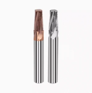
Mold designs often push full-thread depth right up to the bottom of the drilled hole, leaving less than half a pitch of clearance. Standard off-the-shelf thread mills carry generous front chamfers that crash into the drill point cone. Commissioning a custom solid carbide thread mill eliminates this risk by grinding the front lead-in flat and adding back-taper relief to clear blind hole bottoms.
Custom tooling also lets us reinforce the reach neck on non-standard pitches or odd flank angles. We grind a compound taper on the neck transition toward the shank, maximizing the cross-sectional moment of inertia without gouging the hole wall. This tailored geometry provides the structural rigidity needed to hold micron-level thread tolerances across long production runs.
Deep Hole Thread Milling Strategy for HRC65 Hardened Steel: Toolpath and Cutting Parameters
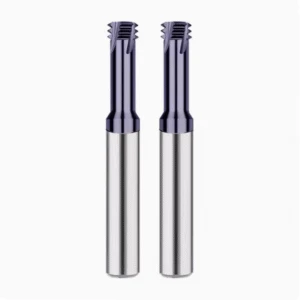
Running an aggressive shallow-hole toolpath on HRC65 tool steel breaks tooling on pass one. At this hardness, the workpiece has zero plastic give, turning every tooth engagement into an intense impact. A robust deep hole thread milling strategy does not aim for aggressive material removal rates; it aims to flatten peak cutting loads and keep the tool neck within its elastic limits.
When tuning customer programs, we regularly overhaul CAM-generated entry routines and canned cycles. A sudden feed spike inside a deep cavity turns tool overhang into a destructive bending lever. By smoothing toolpaths into continuous-curvature helical arcs and staging radial depths, you protect the spindle and prevent edge failure.
Climb Milling vs. Conventional Milling and the Role of Arc In/Out in Controlling Tool-Tip Impact
Climb milling is mandatory when cutting hardened steels because it cuts chips from thick to thin. In conventional milling, the tooth starts at zero thickness, rubbing and burnishing against the abrasive work surface. That friction work-hardens the material, strips the PVD coating, and excites immediate chatter. Climb milling bites cleanly into the cut, protecting the cutting edge from rubbing.
However, straight radial entry during climb milling shocks the tool tip, causing immediate micro-chipping on the rake face. We always program a 90° or 180° smooth entry arc (arc in/out) paired with helical Z-ramping. This rolls the cutter gradually into the cut from a zero-degree engagement angle, buffering radial forces and keeping the overhung tool stable.
Radial Multi-Pass Strategy and Feed-per-Tooth (Fz) Control
Plunging to full thread depth in a single pass on HRC65 steel is a guaranteed break. Long-reach operations require a radial multi-pass strategy, stepping out the thread over two or three passes. Split your stock unevenly: take 60% to 65% on the first roughing pass, 25% to 30% on the semi-finishing pass, and leave a final 0.015 to 0.02 mm spring pass to wipe away deflection taper.
Watch your programmed feed per tooth (Fz) during internal circular interpolation. Because the tool path center radius is much smaller than the cutting edge radius, actual chip thickness can double if uncorrected. For small-diameter deep threads, hold effective Fz between 0.008 and 0.018 mm/tooth. This stays above the edge-hone rubbing threshold without overloading the tool shank.
Critical Cutting Speed (Vc) for Deep-Hole Overhangs and Chip Evacuation via MQL or Through-Tool Coolant
Running high surface footage (Vc) in deep holes is a common mistake. Long-reach setups amplify centrifugal vibration, and excess speed spikes cutting zone heat. Once thermal limits are breached, the cobalt binder softens, causing rapid edge wear. For deep holes in HRC65 steel, keep Vc conservatively between 25 and 45 m/min to maintain edge thermal stability.
Flood coolant often backfires in deep blind holes because thermal cycling causes micro-cracking, and the fluid cannot flush chips out of the cavity. Instead, run dry high-pressure air or Minimum Quantity Lubrication (MQL) through the spindle (through-coolant). A 15 to 20 bar air blast atomizes lubricant directly onto the cut while blowing micro-chips up and out of the hole, stopping recutting completely.

Deep Hole Thread Milling Accuracy Control: Pitch Diameter and Pitch Tolerance
Machine shops often assume that a 5-axis machining center with sub-micron positioning guarantees on-size threads. When milling HRC65 steel past 4D overhang, physical deflection shatters that assumption. Reliable deep hole thread milling accuracy control does not chase the myth of zero deflection; it relies on a closed-loop machining strategy that systematically predicts tool flex, thermal drift, and workpiece spring-back.
In automotive stamping and mold shops across Europe and the US, dimensional scrap rarely stems from a single bad pass. It builds up across the entire process chain. Blindly tweaking tool radius wear offsets without auditing the pilot hole only bells out the entrance while leaving the bottom undersized. You must isolate each error source to hold repeatable tolerances on high-hardness parts.
The Foundational Impact of Pilot Hole Diameter, Perpendicularity, and Quenching-Induced Deformation
Never blame the thread mill until you measure the pre-drilled pilot hole. Vacuum hardening to HRC65 triggers martensitic phase shifts, causing asymmetrical shrinkage, bore taper, and out-of-round hole walls. If a hard-drilled or hard-milled bore is tight by just 0.02 mm, the thread mill cuts extra stock at the minor crest and root. This unexpected radial load forces immediate tool deflection.
Angular drift in the pilot hole creates equally severe problems. When the drilled centerline tilts, the tool’s helical path cuts uneven stock around the circumference. Cutting forces spike and drop every rotation, triggering heavy vibration. We always qualify the hole with class-X pin gauges and bore micrometers before milling. Cutting threads inside a skewed or tapered hole makes precision threading impossible.
Correcting Taper Caused by Tool Deflection via CNC Tool Radius Wear Compensation
Tool deflection is inevitable when hanging a slender tool past 4D. The pitch diameter at the blind-hole bottom will always cut smaller than at the entrance. Never try to fix this taper simply by bumping the global CNC tool radius wear offset. While opening the bottom to size, this moves the rigid upper shank too far out, overcutting the entrance and failing the “no-go” gauge.
A reliable fix requires segmented variable-radius interpolation or reverse-taper compensation. Using macro programming or CAM taper functions, divide the thread depth into discrete axial zones. Add a tiny radial expansion (3 to 6 µm) near the bottom to offset shank flex, then take a 0.005 to 0.01 mm spring pass. This counteracts mechanical tool flex without overloading the carbide neck.
Rapid On-Site Troubleshooting for Thread Gauge Failures and Thread Profile Distortion
When the “go” gauge binds or the “no-go” gauge slips past allowable turns, do not immediately swap tools or scrap the part. In our field audits, parts flagged for out-of-spec pitch diameters often suffer from thread profile distortion. Under a toolmaker’s microscope, we frequently find distorted root radii, 60° flank wave marks from vibration, or hardened micro-burrs rolled over the thread crests.
Run this quick three-step check on your machine: First, inspect the thread grooves with a high-intensity borescope for packed chips or galling marks. Next, check the tool’s cutting edges on an optical comparator to see if the crest rounded or micro-chipped. Finally, verify the pitch-line taper on a CMM. Separating deflection errors from profile distortion tells you whether to tweak offsets or change speeds.
Case Study: D2 Tool Steel Thread Milling Optimization on Hardened Molds
The tooling geometries, multi-pass toolpaths, and taper compensation methods we discussed are practical solutions refined on production floors. In this case study: D2 tool steel thread milling, we highlight an actual mold job to demonstrate how tool rigidity, path smoothing, and runout control interact in extreme conditions.
Production bottlenecks rarely stem from a single machine limitation; they come from several small oversights compounding down the line. If you are struggling with rapid flank wear, broken taps, or tapered threads in hard tool steels, walk through this troubleshooting workflow. Auditing machine rigidity, internal air pressure, and dynamic runout often eliminates edge chipping completely.
Optimizing Tool Life for Blind-Hole Threading (Aspect Ratio > 4D): From Breaking Tools Every 3 Parts to 20 Holes per Tool
A client was cutting M5 blind threads at 4.2D depth into precision D2 die inserts hardened to HRC 64–65. They ran a standard full-profile necked tool in a single full-depth pass, chipping teeth from bottom-hole vibration and scrapping tools every two to three holes. We switched them to a 3-flute anti-vibration cutter featuring unequal flute spacing, a thick core, and an aggressive tip-relief chamfer that eliminated blind-bottom bottoming.
Next, we replaced the straight plunge with a 180° helical arc-in entry and split the thread depth into three radial passes, leaving a final 0.015 mm spring pass for deflection. We also added a 20-bar dry through-air blast to clear chips out of the bottom. Tool life jumped from 3 holes to over 20 holes per tool, with the “go” gauge spinning cleanly to depth and the “no-go” gauge stopping dead at one turn.
Three Details Regarding Tool Setting and Runout in Deep-Hole Machining Often Overlooked by Operators
Overhung tools act like long levers, meaning tiny runout errors at the toolholder magnify significantly at the cutting tip. The first oversight is measuring runout at the holder nose rather than out on the tool flutes. For overhangs past 4D, you must indicate the cutting teeth directly, dialing dynamic runout down to under 0.003 mm (0.0001″) TIR to ensure all flutes share the cutting load equally.
The second oversight is tool-setter pre-load deflection along the Z-axis. Touching off a slender tool against a stiff tactile probe flexes the shank axially, throwing off the programmed depth and causing bottom crashes. Finally, always verify the drilled hole’s true depth and drill-point cone angle. Leaving less than half a pitch of clearance at the hole bottom invites rapid tool breakage.
If you are cutting tool steels hardened past HRC60 or struggling with tapered threads and chipped edges in deep, small-diameter blind holes, review your operational parameters, hole geometry, and heat-treat data. By analyzing your spindle dynamics, part clearances, and cycle-time goals, we can help engineer a reliable tooling package and toolpath strategy tailored to your exact setup.